LWL04 -- LoRaWAN Water Leak Sensor User Manual

Table of Contents:
- 1. Introduction
- 2. Configure LWL04 to connect to LoRaWAN network
- 3. Configure LWL04
- 3.1 Configure Methods
- 3.2 General Commands
- 3.3 Commands special design for LWL04
- 3.3.1 Set Transmit Interval Time
- 3.3.2 Set Power Output Duration
- 3.3.3 Enable / Disable Alarm
- 3.3.4 Set system time
- 3.3.5 Set Time Sync Mode
- 3.3.6 Alarm Base on Timeout
- 3.3.7 The working mode of the total water leakage event
- 3.3.8 Regularly update a confirm uplink when water leaks
- 3.3.9 Delay time for state changes to take effectEdit
- 3.3.10 Clear the leak count and the duration of the last leak
- 3.3.11 Set the count value of the number of leaks
- 4. Battery & How to replace
- 5. OTA Firmware update
- 6. FAQ
- 7. Order Info
- 8. Packing Info
- 9. Support
1. Introduction
1.1 What is LWL04 LoRaWAN Water Leak Sensor
The Dragino LWL04 is a LoRaWAN Water Leak Sensor. When there is water between the bottom 3 metal posts, the LWL04 indicates a water leak event and uplink to IoT server via LoRaWAN network.
The Dragino LWL04 does not need to be fixed, only placed on the ground. The bottom three metal columns can adjust the height. Only when there is water between the three metal columns, it will cause a short circuit alarm.
LWL04 can be activated from the bottom of the housing with a magnet, and the light will indicate when the magnet is close. Its main unit has a sealing ring, which can achieve IP65 waterproof.
LWL04 is powered by CR123A non-rechargeable battery and target for long time use, these batteries can provide about 16,000 ~ 70,000 uplink packets, which result in 2 ~ 10 years battery life. After battery running out, user can easily open the enclosure and replace with CR123A batteries.
The LWL04 will send periodically data every day as well as for each water leak event. It also counts the water leak times and calculate last water leak duration. User can also disable the uplink for each water leak event, instead, device can count each event and uplink periodically.
Each LWL04 is pre-load with a set of unique keys for LoRaWAN registration, register these keys to LoRaWAN server and it will auto connect after power on.
1.2 Features
- LoRaWAN Class A v1.0.3
- Frequency Bands: CN470/EU433/KR920/US915/EU868/AS923/AU915/IN865/RU864
- Water Leak detect
- Support wireless OTA update firmware
- Downlink to change configure
- Uplink on periodically and water leak event
- CR123A 1500mAh Battery
- IP65 waterproof
1.3 Storage & Operation Temperature
Support operating temperature -40℃~+85℃, but the extreme temperature will have a certain impact on the battery discharge life.
Note: Storage and operation temperature depends on the battery type, this manual LWL04 shipped original battery as an example, see CR123A RAMWAY BATTERY.
1.4 Applications
- Smart Factory
- Smart Buildings & Home Automation
1.5 Sleep mode and working mode
Deep Sleep Mode: Sensor doesn't have any LoRaWAN activate. This mode is used for storage and shipping to save battery life.
Working Mode: In this mode, Sensor will work as LoRaWAN Sensor to Join LoRaWAN network and send out sensor data to server. Between each sampling/tx/rx periodically, sensor will be in IDLE mode), in IDLE mode, sensor has the same power consumption as Deep Sleep mode.
1.6. Power ON LWL04
The LWL04 is shipped in a battery-mounted condition and the user can activate the LWL04 by simply placing the magnet at the bottom center of the LWL04 for more than 3 seconds.
When the user uses the magnet to get close to the bottom center of the LWL04, the green light is on to indicate successful sensing. Keeping the magnet position still for 3 seconds, the green light is always on for 3 seconds, then the green light blinks rapidly for 5 times, the node activation is successful. Please refer to Magnet action & LEDs for specific LED indication status.
Example diagram of LWL04 activation operation ( Soft magnet operation on the bottom of the node & LED status on the front of the node):

1.7 Magnet action & LEDs
When the magnet is near the bottom center position of LWL04, the green light indicates that the magnet is successfully induced.
| Magnet action | Function | Action |
|---|---|---|
| Hold magnet induction between 1s < time < 3s | Send an uplink | If sensor is already Joined to LoRaWAN network, sensor will send an uplink packet, blue led will blink once. |
| Hold magnet induction for more than 3s | Active Device | Green led will fast blink 5 times, device will enter OTA mode for 3 seconds. And then start to JOIN LoRaWAN network. |
| Quickly activate magnet induction 5 times | Deactivate Device | Red led will solid on for 5 seconds. Means device is in Deep Sleep Mode. |
1.8 Pin Definitions

1.9 Mechanical


2. Configure LWL04 to connect to LoRaWAN network
2.1 How it works?
The LWL04 is configured as LoRaWAN OTAA Class A mode by default. It has OTAA keys to join LoRaWAN network. To connect a local LoRaWAN network, you need to input the OTAA keys in the LoRaWAN IoT server and press the button to activate the LWL04. It will automatically join the network via OTAA and start to send the sensor value. The default uplink interval is 2 hours.
2.2 Quick guide to connect to LoRaWAN server (OTAA)
Here shows an example for how to join the TTN V3 Network. Below is the network structure, we use LG308N as LoRaWAN gateway here.

The LG308 is already set to connect to TTN V3 network . What we need to now is only configure the TTN V3:
Step 1: Create a device in TTN V3 with the OTAA keys from LWL04.
Each LWL04 is shipped with a sticker with unique device EUI:

You can enter this key in the LoRaWAN Server portal. Below is TTN screen shot:
Create the application.


Add devices to the created Application.


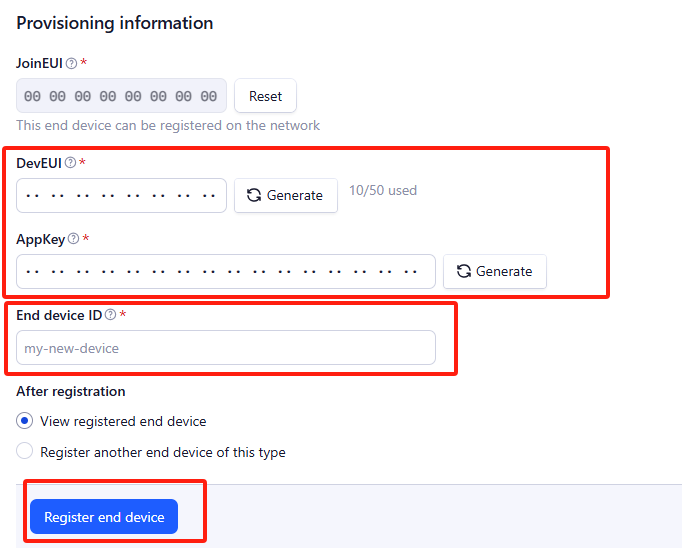
Enter end device specifics manually.

Add DevEUI and AppKey. Customize a platform ID for the device.
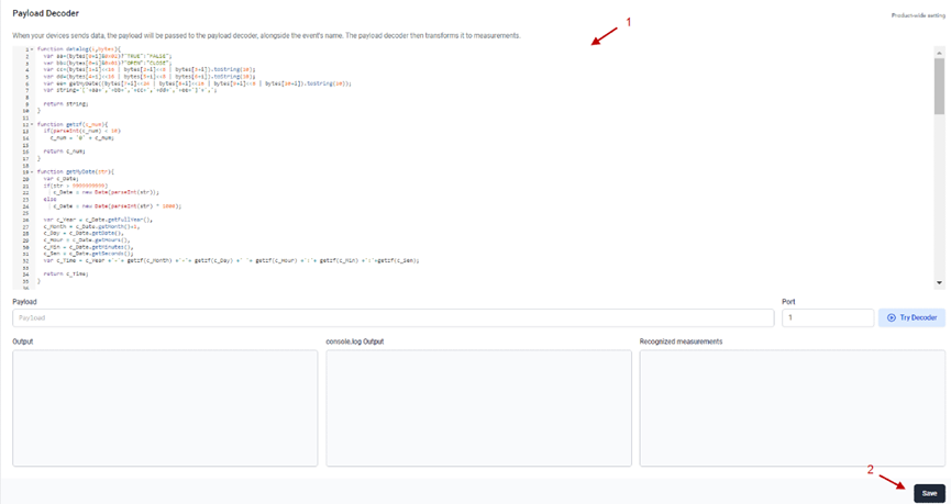
Step 2: Add decoder.
In TTN, user can add a custom payload so it shows friendly reading.
Click this link to get the decoder: https://github.com/dragino/dragino-end-node-decoder/tree/main/
Below is TTN screen shot:


Step 3: Power on LWL04 and it will auto join to the TTN V3 network. After join success, it will start to upload message to TTN V3 and user can see in the panel.

2.3 Uplink Payload
2.3.1 Device Status, FPORT=5
Include device configure status. Once LWL04 Joined the network, it will uplink this message to the server. After that, LWL04 will uplink Device Status every 12 hours.
Users can also use the downlink command(0x26 01) to ask LWL04 to resend this uplink. This uplink payload also includes the DeviceTimeReq to get time.
The Payload format is as below.
| Device Status (FPORT=5) | |||||
| Size (bytes) | 1 | 2 | 1 | 1 | 2 |
| Value | Sensor Model | Firmware Version | Frequency Band | Sub-band | BAT |
Example parse in TTN:

Sensor Model: For LWL04, this value is 0x36
Firmware Version: 0x0100, Means: v1.0.0 version
Frequency Band:
0x01: EU868
0x02: US915
0x03: IN865
0x04: AU915
0x05: KZ865
0x06: RU864
0x07: AS923
0x08: AS923-1
0x09: AS923-2
0x0a: AS923-3
0x0b: CN470
0x0c: EU433
0x0d: KR920
0x0e: MA869
Sub-Band:
AU915 and US915:value 0x00 ~ 0x08
CN470: value 0x0B ~ 0x0C
Other Bands: Always 0x00
Battery Info:
Check the battery voltage.
Ex1: 0x0BE3 = 3043mV
Ex2: 0x0B49 = 2889mV
2.3.2 Sensor Configuration, FPORT=4
LWL04 will only send this command after getting the downlink command (0x26 02) from the server.
| Size(bytes) | 3 | 1 | 1 | 2 | 1 |
| Value | TDC (unit: sec) | Disalarm | Keep status | Keep time (unit: sec) | Leak alarm time |
Example parse in TTNv3

TDC: (default: 0x001C20)
Uplink interval for the Leak/No leak Event, default value is 0x001C20 which is 7200 seconds = 2 hours.
Disalarm: (default: 0)
If Disalarm = 1, LWL04 will only send uplink at every TDC periodically. This is normally use for pulse meter application, in this application, there are many Leak/No leak event, and platform only care about the total number of pulse.
If Disalarm = 0, LWL04 will send uplink at every TDC periodically and send data on each Leak/No leak event. This is useful for the application user need to monitor the Leak/No leak event in real-time.
Note: When Disalarm=0, a high frequently Leak/No leak event will cause lots of uplink and drain battery very fast.
Keep Status & Keep Time
Shows the configure value of Alarm Base on Timeout Feature
- Leak alarm time
Regularly update a confirm uplink when water leaks, default value is 0x0A which is 10 minutes.
2.3.3 Real-Time Open/Close Status, Uplink FPORT=2
LWL04 will send this uplink after Device Status once join the LoRaWAN network successfully. And LWL04 will:
1. periodically send this uplink every 2 hours, this interval can be changed.
2. There is an Leak/No leak event.
Uplink Payload totals 11 bytes.
| Real-Time Open/Close Status, FPORT=2 | ||||
|---|---|---|---|---|
| Size(bytes) | 1 | 3 | 3 | 4 |
| Value | Status & Alarm | Total leak events | Last leak | Unix TimeStamp |
Status & Alarm:
| Size(bit) | [bit5:bit4] | bit3 | bit2 | bit1 | bit0 |
| Value | Reserve | Count mod | TDC flag 0:No;1:Yes | Alarm 0: No Alarm;1: Alarm | Status 0: No leak, 1: leak |
Example parse in TTNv3

Count mod:Default=0
0 : Uplink total leak times since factory
1: Uplink total leak times since last FPORT=2 uplink.
- TDC flag
When the flag is 1, it means sending packets at normal time intervals.
Otherwise, it is a packet sent at non-TDC time.
Alarm
Status
This bit is 1 when the leak sensor is leak and 0 when it is no leak.
Total leak events
Total pulse/counting base on leak.
Range (3 Bytes) : 0x000000 ~ 0xFFFFFF . Max: 16777215
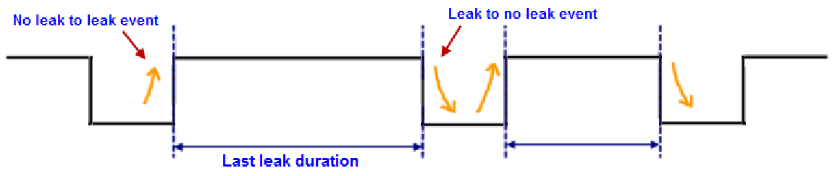
Last leak duration
Leak sensor last leak duration.
Unit: sec.
2.3.4 Historical Water Leak/No leak Event, FPORT=3
LWL04 stores sensor values and users can retrieve these history values via the downlink command.
The historical payload includes one or multiplies entries and every entry has the same payload as Real-Time leak/no leak status.
| Real-Time Open/Close Status, FPORT=3 | ||||
|---|---|---|---|---|
| Size(bytes) | 1 | 3 | 3 | 4 |
| Value | Status & Alarm | Total leak events | Last leak | Unix TimeStamp |
Status & Alarm:
| Size(bit) | bit7 | bit6 | [bit5:bit4] | bit3 | bit2 | bit1 | bit0 |
| Value | Reserve | Poll Message Flag | Reserve | Count mod | TDC flag 0:No;1:Yes | Alarm 0: No Alarm;1: Alarm | Status 0: No leak, 1: leak |
Each data entry is 11 bytes and has the same structure as Real-Time open/close status, to save airtime and battery, LWL04 will send max bytes according to the current DR and Frequency bands.
For example, in the US915 band, the max payload for different DR is:
1. DR0: max is 11 bytes so one entry of data
2. DR1: max is 53 bytes so devices will upload 4 entries of data (total 44 bytes)
3. DR2: total payload includes 11 entries of data
4. DR3: total payload includes 22 entries of data.
LWL04 doesn't have any data in the polling time. It will uplink 11 bytes of 0

Access via serial port:

Downlink: 0x31+Start time +End time +Uplink interval(Unit: seconds)
0x31 66 E0 F2 98 66 E0 F4 F0 05
Uplink:
44 00 00 00 00 00 00 66 E0 F2 B2 44 00 00 00 00 00 00 66 E0 F3 22 44 00 00 00 00 00 00 66 E0 F3 9A 44 00 00 00 00 00 00 66 E0 F4 12 44 00 00 00 00 00 00 66 E0 F4 8A
Parsed Value:
[COUNTMOD,TDC_FLAG,ALARM, WATER_LEAK_STATUS, WATER_LEAK_TIMES, LAST_WATER_LEAK_DURATION, TIME]
[SUM,YES,FALSE,NO LEAK,0,0,2024-09-11 01:30:26],
[SUM,YES,FALSE,NO LEAK,0,0,2024-09-11 01:32:18],
[SUM,YES,FALSE,NO LEAK,0,0,2024-09-11 01:34:18],
[SUM,YES,FALSE,NO LEAK,0,0,2024-09-11 01:36:18],
[SUM,YES,FALSE,NO LEAK,0,0,2024-09-11 01:38:18],
2.4 Datalog Feature
Datalog Feature is to ensure IoT Server can get all sampling data from Sensor even if the LoRaWAN network is down. For each sampling, LWL04 will store the reading for future retrieving purposes.
Note:After the device is reset, in cumulative counting mode, the last stored leak count value will be read as the initial value.
2.4.1 Unix TimeStamp
LWL04 use Unix TimeStamp format based on
Users can get this time from the link: https://www.epochconverter.com/ :
Below is the converter example
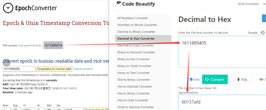
So, we can use AT+TIMESTAMP=1726018200 or downlink 3066E0F29800 to set the current time 2021 – Jan -- 29 Friday 03:03:25 2024 - September --11 Wednesday 01:30:00
2.4.2 Set Device Time
There are two ways to set the device's time:
1. Through LoRaWAN MAC Command (Default settings)
Users need to set SYNCMOD=1 to enable sync time via the MAC command.
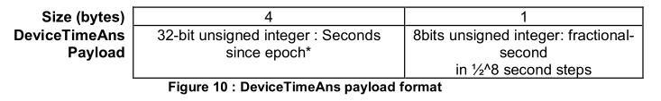
Once LWL04 Joined the LoRaWAN network, it will send the MAC command (DeviceTimeReq) and the server will reply with (DeviceTimeAns) to send the current time to LWL04. If LWL04 fails to get the time from the server, LWL04 will use the internal time and wait for the next time request [via Device Status (FPORT=5)].
Note: LoRaWAN Server needs to support LoRaWAN v1.0.3(MAC v1.0.3) or higher to support this MAC command feature.
2. Manually Set Time
Users need to set SYNCMOD=0 to manual time, otherwise, the user set time will be overwritten by the time set by the server.
2.5 Show Data in DataCake IoT Server
Datacake IoT platform provides a human-friendly interface to show the sensor data, once we have sensor data in TTN V3, we can use Datacake to connect to TTN V3 and see the data in Datacake. Below are the steps:
Step 1: Link TTNv3 to Datacake.https://docs.datacake.de/lorawan/lns/thethingsindustries#create-integration-on-tti
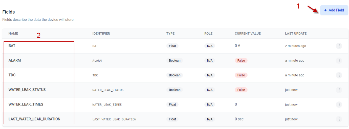
Step 2: Add LWL04 to Datacake.


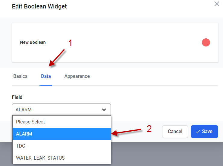
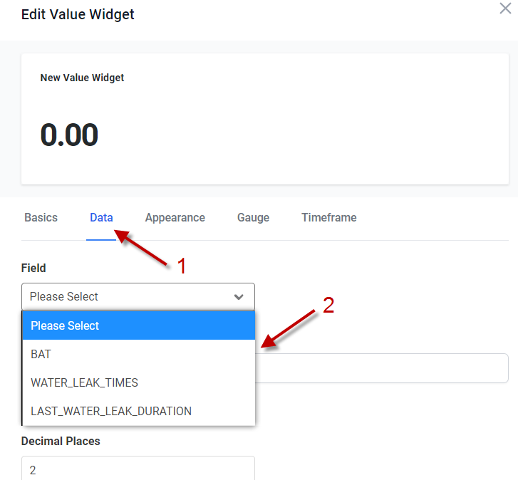
Step 3: Configure LWL04 in Datacake.


2.6 Frequency Plans
The LWL04 uses OTAA mode and below frequency plans by default. Each frequency band use different firmware, user update the firmware to the corresponding band for their country.
3. Configure LWL04
3.1 Configure Methods
LWL04 supports below configure method:
- AT Command via UART Connection : See UART Connection.
- LoRaWAN Downlink. Instruction for different platforms: See IoT LoRaWAN Server section.
3.2 General Commands
These commands are to configure:
- General system settings like: uplink interval.
- LoRaWAN protocol & radio related command.
They are same for all Dragino Devices which support DLWS-005 LoRaWAN Stack. These commands can be found on the wiki:
End Device AT Commands and Downlink Command
3.3 Commands special design for LWL04
These commands only valid for LWL04, as below:
3.3.1 Set Transmit Interval Time
Feature: Change LoRaWAN End Node Transmit Interval.
AT Command: AT+TDC
| Command Example | Function | Response |
|---|---|---|
| AT+TDC=? | Show current transmit Interval | 7200000 |
| AT+TDC=1200000 | Set Transmit Interval | OK |
Downlink Command: 0x01
Format: Command Code (0x01) followed by 3 bytes time value.
If the downlink payload=01001C20, it means set the END Node's Transmit Interval to 0x001C20(H)=7200(D) seconds, while type code is 01.
- Example 1: Downlink Payload: 01001C20 // Set Transmit Interval (TDC) = 7200 seconds
- Example 2: Downlink Payload: 010004B0 // Set Transmit Interval (TDC) = 1200 seconds
3.3.2 Set Power Output Duration
Control the output duration 5V . Before each sampling, device will
1. first enable the power output to external sensor,
2. keep it on as per duration, read sensor value and construct uplink payload
3. final, close the power output.
AT Command: AT+5VT
| Command Example | Function | Response |
|---|---|---|
| AT+5VT=? | Show 5V open time. | 0 (default) OK |
| AT+5VT=1000 | Close after a delay of 1000 milliseconds. | OK |
Downlink Command: 0x07
Format: Command Code (0x07) followed by 2 bytes.
The two bytes following the function code 0x07 set the opening time of 5V.
- Example 1: Downlink Payload: 070000 ---> AT+5VT=0
- Example 2: Downlink Payload: 0701F4 ---> AT+5VT=500
3.3.3 Enable / Disable Alarm
Feature: Enable/Disable Alarm for open/close event. Default value 0.
AT Command: AT+DISALARM
| Command Example | Function | Response |
|---|---|---|
| AT+DISALARM=1 | End node will only send packet in TDC time. | OK |
| AT+DISALARM=0 | End node will send packet in TDC time or status change for water leak sensor | OK |
Downlink Command: 0xA7
- Downlink payload: 0xA7 01 // Same as AT+DISALARM=1
- Downlink payload: 0xA7 00 // Same as AT+DISALARM=0
3.3.4 Set system time
Feature: Set system time, Unix format. See here for format detail.
AT Command: AT+TIMESTAMP
| Command Example | Function | Response |
|---|---|---|
| AT+TIMESTAMP=1725957832 | Set System time to 2024-09-10 08:43:52 | OK |
Downlink Command: 0x30
0x3066E006C800 // Set timestamp to 0x(66E006C800),Same as AT+TIMESTAMP=1725957832
3.3.5 Set Time Sync Mode
Feature: Enable/Disable Sync system time via LoRaWAN MAC Command (DeviceTimeReq), LoRaWAN server must support v1.0.3 protocol to reply to this command.
SYNCMOD is set to 1 by default. If user wants to set a different time from the LoRaWAN server, the user needs to set this to 0.
AT Command: AT+SYNCMOD
| Command Example | Function | Response |
|---|---|---|
| AT+SYNCMOD=1 | Enable Sync system time via LoRaWAN MAC Command (DeviceTimeReq) The default is zero time zone. | OK |
| AT+SYNCMOD=1,8 | Enable Sync system time via LoRaWAN MAC Command (DeviceTimeReq) Set to East eight time zone. | OK |
| AT+SYNCMOD=1,-12 | Enable Sync system time via LoRaWAN MAC Command (DeviceTimeReq) Set to West Twelve Time Zone. | OK |
Downlink Command: 0X28
0x28 01 // Same as AT+SYNCMOD=1
0x28 01 08 // Same as AT+SYNCMOD=1,8
0x28 01 F4 // Same as AT+SYNCMOD=1,-12
0x28 00 // Same as AT+SYNCMOD=0
3.3.6 Alarm Base on Timeout
LWL04 can monitor the timeout for a status change, this feature can be used to monitor some events such as door opening too long etc.
User configure this feature by using:
AT Command: AT+TTRIG=AA,BB
AA: When AA=0, the monitoring state: changes from leakage to no leakage.
When AA=1, the monitoring state: changes from no leakage to leakage.
BB: Holding time after state change.
Example:
AT+TTRIG=1,30 --> When status change from no leak to leak, and device keep in leak status for more than 30 seconds. LWL04 will send an uplink packet, the Alarm bit (the second bit of 1st byte of payload) on this uplink packet is set to 1.
AT+TTRIG=0,30 --> When status change from leak to no leak, and device keep in no leak status for more than 30 seconds. LWL04 will send an uplink packet, the Alarm bit (the second bit of 1st byte of payload) on this uplink packet is set to
AT+TTRIG=0,0 --> Default Value, disable timeout Alarm.
Downlink Command: 0xA9 aa bb cc
A9: Command Type Code
aa: status to be monitored
bb cc: timeout
Example:
- Downlink payload: 0xA9 01 00 1E --> Equal to AT+TTRIG=1,30
- Downlink payload: 0xA9 00 00 00 --> Equal to AT+TTRIG=0,0 //Disable timeout Alarm.
3.3.7 The working mode of the total water leakage event
AT Command: AT+COUNTMOD
- AT+COUNTMOD=0 //Default Value, Total leak events since factory.
- AT+COUNTMOD=1 //Total leak events since last TDC uplink.
Downlink Command: 0x0B
- Downlink payload: 0x0B00 // Same as AT+COUNTMOD=0
- Downlink payload: 0x0B01 // Same as AT+COUNTMOD=1
3.3.8 Regularly update a confirm uplink when water leaks
AT Command: AT+LEAKALARM
- AT+LEAKALARM=10 --> Default Value, A periodically update at every 10 minutes when in water leak.
- AT+LEAKALARM=0 --> Disable a periodically update when in water leak.
Downlink Command: 0x0C
Format: Command Code (0x0C) followed by 1 byte.
- Downlink payload: 0xAC 0A // Same as AT+LEAKALARM=10
- Downlink payload: 0xAC 00 // Same as AT+LEAKALARM=0
3.3.9 Delay time for state changes to take effectEdit
AT Command: AT+DETEDELAY
AT+DETEDELAY=50 --> Default Value, Set state change, valid signal is 50ms.
AT+DETEDELAY=0 --> Disable valid signal detection..
Downlink Command: 0x0D aa bb
0D: Command Type Code
aa bb: timeout
Example:
- Downlink payload: 0x0D 00 32 // Same as AT+DETEDELAY=50
- Downlink payload: 0x0D 00 00 // Same as AT+DETEDELAY=0
3.3.10 Clear the leak count and the duration of the last leak
AT Command: AT+CLRC
| Command Example | Function | Response |
|---|---|---|
| AT+CLRC | clear the leak count and the duration of the last leak. | OK |
Downlink Payload: 0xA601
The sensor will clear the leak count and the duration of the last leak.
3.3.11 Set the count value of the number of leaks
AT Command: AT+SETCNT
| Command Example | Function | Response |
|---|---|---|
| AT+SETCNT=100 | Set the leak count value to 100 | OK |
Downlink Payload: 0xA5
Format: Command Code (0xA5) followed by 3 bytes.
- 0xA5 00 00 64 //Same as AT+SETCNT=100
4. Battery & How to replace
4.1 Battery Type and replace
LWL04 is equipped with 1 x CR123A battery. If the batterys running low(see 2.3~2.5v in the platform). User can buy generic CR123A battery and replace it.
Note: Make sure the direction is correct when install the CR123A battery.
Important Notice: Make sure use new CR123A battery and the battery doesn't have broken surface.
Example of CR123A battery:

4.2 Power Consumption Analyze
Dragino battery powered products are all run in Low Power mode. User can check the guideline from this link to calculate the estimate battery life:
Battery Info & Power Consumption Analyze .
5. OTA Firmware update
User can change firmware LWL04 to:
- Change Frequency band/ region.
- Update with new features.
- Fix bugs.
Firmware and changelog can be downloaded from : Firmware download link
Methods to Update Firmware:
- (Recommanded way) OTA firmware update via wireless: http://wiki.dragino.com/xwiki/bin/view/Main/Firmware%20OTA%20Update%20for%20Sensors/
- Update through UART TTL interface: Instruction.
6. FAQ
7. Order Info
Part Number: LWL04-XXX
XXX:
- EU433: frequency bands EU433
- EU868: frequency bands EU868
- KR920: frequency bands KR920
- CN470: frequency bands CN470
- AS923: frequency bands AS923
- AU915: frequency bands AU915
- US915: frequency bands US915
- IN865: frequency bands IN865
8. Packing Info
Package Includes:
- LWL04 x 1

Dimension and weight:
- Device Size: cm
- Device Weight: g
- Package Size / pcs : cm
- Weight / pcs : g
9. Support
- Support is provided Monday to Friday, from 09:00 to 18:00 GMT+8. Due to different timezones we cannot offer live support. However, your questions will be answered as soon as possible in the before-mentioned schedule.
- Provide as much information as possible regarding your enquiry (product models, accurately describe your problem and steps to replicate it etc) and send a mail to Support@dragino.cc.