- LA66 LoRaWAN Module
- LA66 LoRaWAN Shield
- Pin Mapping & LED
- Example: Use AT Command to communicate with LA66 module via Arduino UNO.
- Example: Join TTN network and send an uplink message, get downlink message.
- Example: Log Temperature Sensor(DHT11) and send data to TTN, show it in DataCake.
- Upgrade Firmware of LA66 LoRaWAN Shield
- LA66 USB LoRaWAN Adapter
LA66 LoRaWAN Module
What is LA66 LoRaWAN Module
Dragino LA66 is a small wireless LoRaWAN module that offers a very compelling mix of long-range, low power consumption, and secure data transmission. It is designed to facilitate developers to quickly deploy industrial-level LoRa and IoT solutions. It helps users to turn the idea into a practical application and make the Internet of Things a reality. It is easy to program, create and connect your things everywhere.
LA66 is a ready-to-use module which includes the LoRaWAN v1.0.4 protocol. External MCU can use AT command to call LA66 and start to transmit data via the LoRaWAN protocol.
Each LA66 module includes a world unique OTAA key for LoRaWAN registration.
Specification
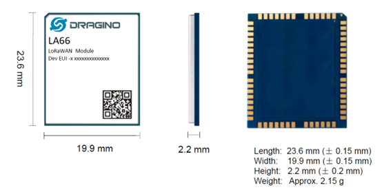
Input Power Range: 1.8v ~ 3.7v
Power Consumption: < 4uA.
Frequency Range: 150 MHz ~ 960 MHz
Maximum Power +22 dBm constant RF output
High sensitivity: -148 dBm
Temperature:
- Storage: -55 ~ +125℃
- Operating: -40 ~ +85℃
Humidity:
- Storage: 5 ~ 95% (Non-Condensing)
- Operating: 10 ~ 95% (Non-Condensing)
LoRa Tx Current: <90 mA at +17 dBm, 108 mA at +22 dBm
LoRa Rx current: <9 mA
I/O Voltage: 3.3v
AT Command
AT Command is valid over Main TXD and Main RXD. Serial Baud Rate is 9600. AT commands can be found in AT Command documents.
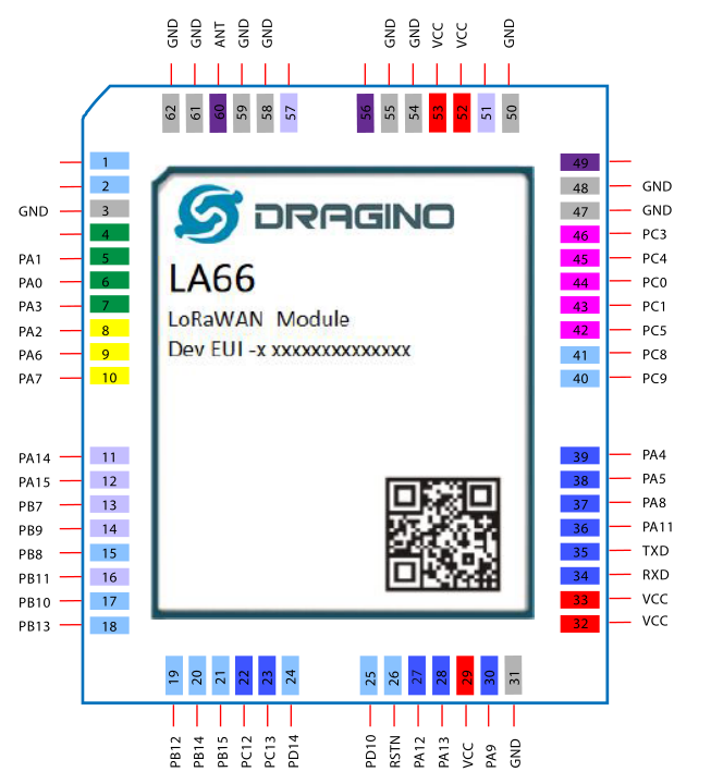
Pin Mapping
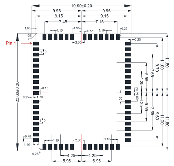
Land Pattern
Part Number
Part Number: LA66-XXX
XX: The default frequency band
- AS923: LoRaWAN AS923 band
- AU915: LoRaWAN AU915 band
- EU433: LoRaWAN EU433 band
- EU868: LoRaWAN EU868 band
- KR920: LoRaWAN KR920 band
- US915: LoRaWAN US915 band
- IN865: LoRaWAN IN865 band
- CN470: LoRaWAN CN470 band
LA66 LoRaWAN Shield
LA66 LoRaWAN Shield is the Arduino Breakout PCB to fast test the features of LA66 module and turn Arduino to support LoRaWAN.
Pin Mapping & LED
Example: Use AT Command to communicate with LA66 module via Arduino UNO.
Example: Join TTN network and send an uplink message, get downlink message.
Example: Log Temperature Sensor(DHT11) and send data to TTN, show it in DataCake.
Upgrade Firmware of LA66 LoRaWAN Shield
what needs to be used
1.LA66 LoRaWAN Shield that needs to be upgraded
2.Arduino
3.USB TO TTL
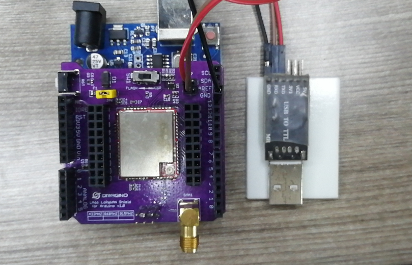
Wiring Schematic
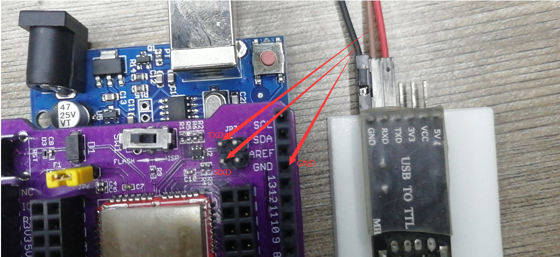
LA66 LoRaWAN Shield >>>>>>>>>>>>USB TTL
GND >>>>>>>>>>>>GND
TXD >>>>>>>>>>>>TXD
RXD >>>>>>>>>>>>RXD
JP6 of LA66 LoRaWAN Shield needs to be connected with yellow jumper cap
Connect to the PC after connecting the wires
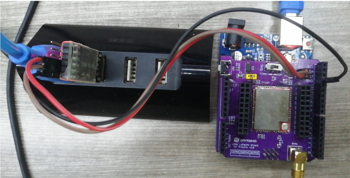
Upgrade steps
Dial the SW1 of the LA66 LoRaWAN Shield to the ISP's location as shown in the figure below
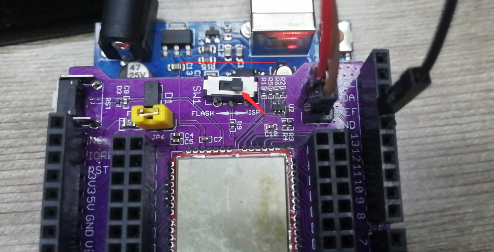
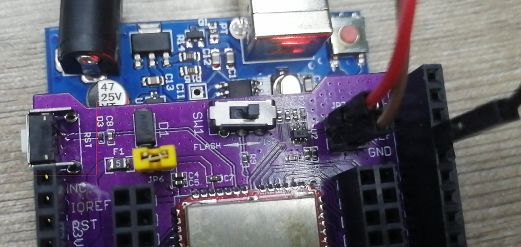
Press the RST switch on the LA66 LoRaWAN Shield once
Open the upgrade application software
Software download link: https://www.dragino.com/downloads/index.php?dir=LSN50-LoRaST/Utility/LSN50N/
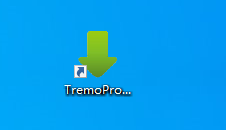
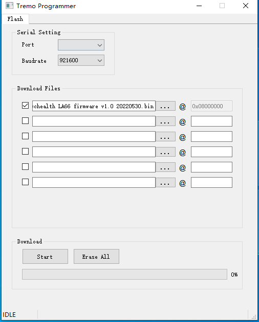
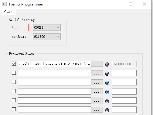
Select the COM port corresponding to USB TTL
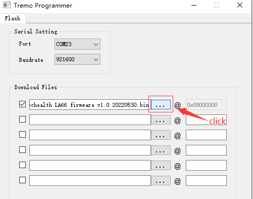
Select the bin file to burn
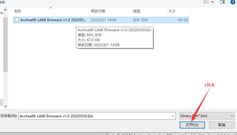
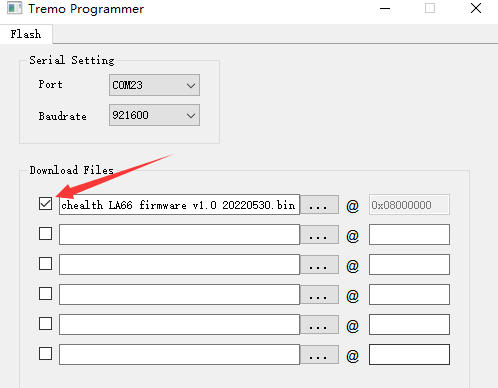
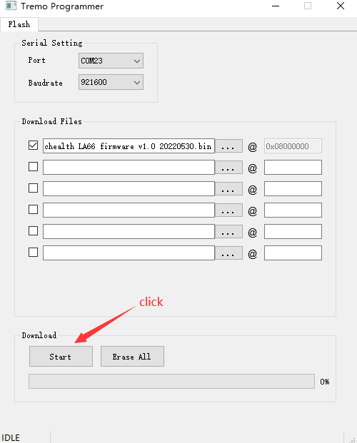
Click to start the download
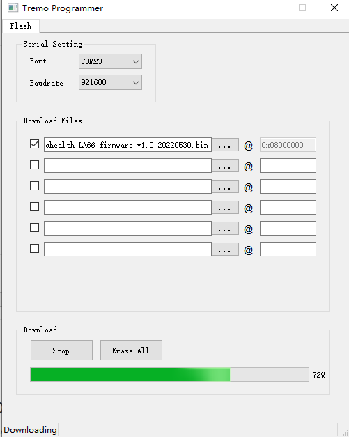
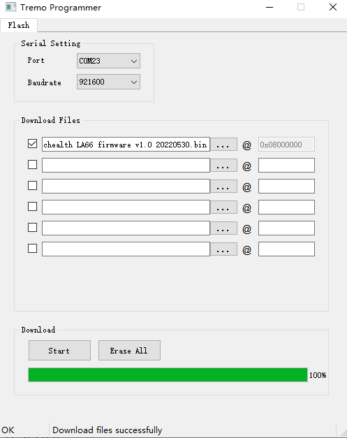
The following figure appears to prove that the burning is in progress
The following picture appears to prove that the burning is successful
LA66 USB LoRaWAN Adapter
LA66 USB LoRaWAN Adapter is the USB Adapter for LA66, it combines a USB TTL Chip and LA66 module which can easy to test the LoRaWAN feature by using PC or embedded device which has USB Interface.
Before use, please make sure that the computer has installed the CP2102 driver
Pin Mapping & LED
Example Send & Get Messages via LoRaWAN in PC
Connect the LA66 LoRa Shield to the PC

Open the serial port tool

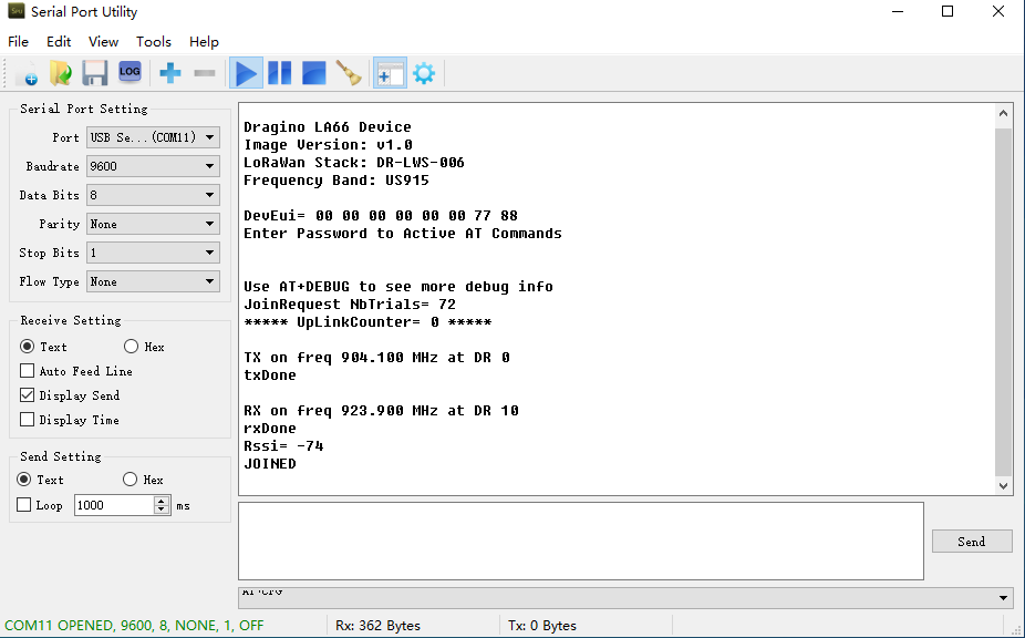
Press the reset switch RST on the LA66 LoRa Shield.
The following picture appears to prove that the LA66 LoRa Shield successfully entered the network
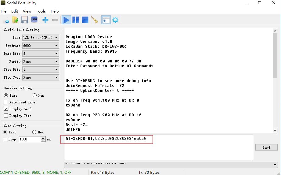
send instructions: AT+SENDB=<confirn_status>,<Fport>,<data_len>,<data>
example: AT+SENDB=01,02,8,05820802581ea0a5
Check to see if TTN received the message

Example Send & Get Messages via LoRaWAN in RPi
Connect the LA66 LoRa Shield to the RPI

Log in to the RPI's terminal and connect to the serial port
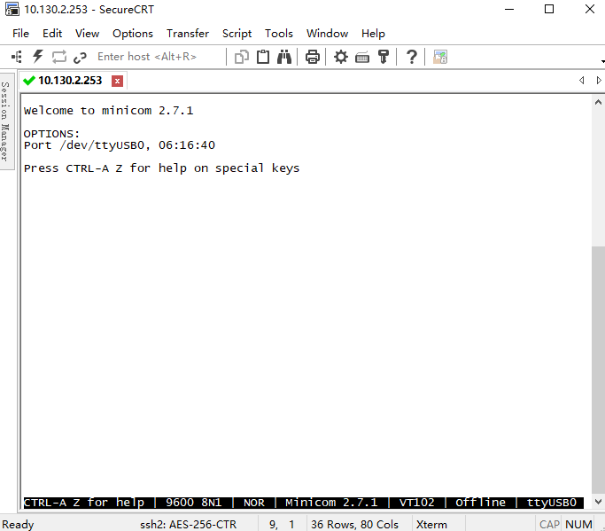
Press the reset switch RST on the LA66 LoRa Shield.
The following picture appears to prove that the LA66 LoRa Shield successfully entered the network
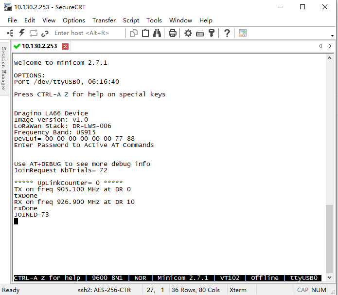
send instructions: AT+SENDB=<confirn_status>,<Fport>,<data_len>,<data>
example: AT+SENDB=01,02,8,05820802581ea0a5
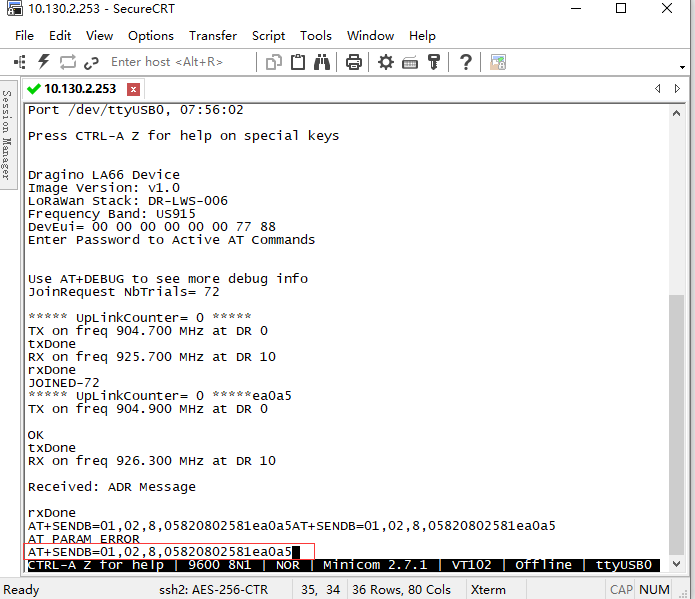
Check to see if TTN received the message

Install Minicom
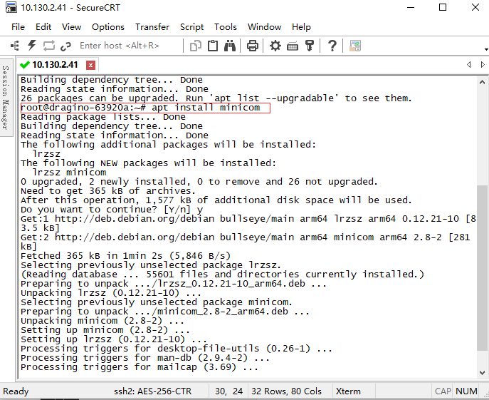
Enter the following command in the RPI terminal
apt update
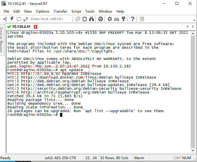
apt install minicom
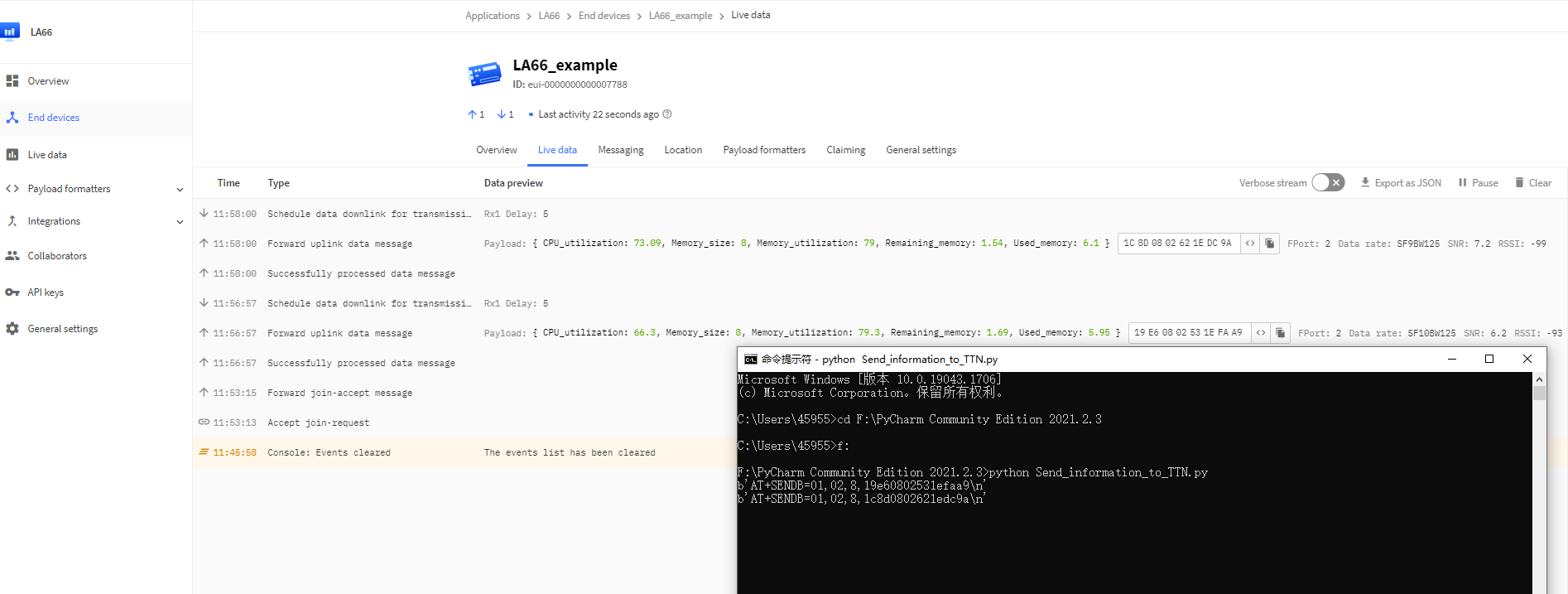
Send PC's CPU/RAM usage to TTN via script.
Take python as an example:
Preconditions:
1.LA66 USB LoRaWAN Adapter works fine
2.LA66 USB LoRaWAN Adapter is registered with TTN
Steps for usage
1.Press the reset switch RESET on the LA66 USB LoRaWAN Adapter
2.Run the script and see the TTN
Example: LA66 USB Module got a message from LA66 LoRa Shield and send the sensor data to NodeRed.
Upgrade Firmware of LA66 USB LoRaWAN Adapter