Table of Contents:
- 1. LA66 LoRaWAN Shield
- 1.1 Overview
- 1.2 Features
- 1.3 Specification
- 1.4 Pin Mapping & LED
- 1.5 Example: Use AT Command to communicate with LA66 module via Arduino UNO.
- 1.6 Example: Join TTN network and send an uplink message, get downlink message.
- 1.7 Example: Log Temperature Sensor(DHT11) and send data to TTN, show it in Node-RED.
- 1.8 Upgrade Firmware of LA66 LoRaWAN Shield
- 2. FAQ
- 3. Order Info
- 4. Reference
1. LA66 LoRaWAN Shield
1.1 Overview
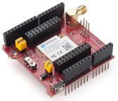
LA66 LoRaWAN Shield is the Arduino shield base on LA66. Users can use LA66 LoRaWAN Shield to rapidly add LoRaWAN or peer-to-peer LoRa wireless function to Arduino projects.
LA66 is a ready-to-use module that includes the LoRaWAN v1.0.3 protocol. The LoRaWAN stack used in LA66 is used in more than 1 million LoRaWAN End Devices deployed world widely. This mature LoRaWAN stack greatly reduces the risk to make stable LoRaWAN Sensors to support different LoRaWAN servers and different countries' standards. External MCU can use AT command to call LA66 and start to transmit data via the LoRaWAN protocol.
Each LA66 module includes a world-unique OTAA key for LoRaWAN registration.
Besides the support of the LoRaWAN protocol, LA66 also supports open-source peer-to-peer LoRa Protocol for the none-LoRaWAN application.
LA66 is equipped with TCXO crystal which ensures the module can achieve stable performance in extreme temperatures.
1.2 Features
- Arduino Shield base on LA66 LoRaWAN module
- Support LoRaWAN v1.0.3 protocol
- Support peer-to-peer protocol
- TCXO crystal to ensure RF performance on low temperature
- SMA connector
- Available in different frequency LoRaWAN frequency bands.
- World-wide unique OTAA keys.
- AT Command via UART-TTL interface
- Firmware upgradable via UART interface
- Ultra-long RF range
1.3 Specification
- CPU: 32-bit 48 MHz
- Flash: 256KB
- RAM: 64KB
- Input Power Range: 1.8v ~ 3.7v
- Power Consumption: < 4uA.
- Frequency Range: 150 MHz ~ 960 MHz
- Maximum Power +22 dBm constant RF output
- High sensitivity: -148 dBm
- Temperature:
- Storage: -55 ~ +125℃
- Operating: -40 ~ +85℃
- Humidity:
- Storage: 5 ~ 95% (Non-Condensing)
- Operating: 10 ~ 95% (Non-Condensing)
- LoRa Tx Current: <90 mA at +17 dBm, 108 mA at +22 dBm
- LoRa Rx current: <9 mA
- I/O Voltage: 3.3v
1.4 Pin Mapping & LED
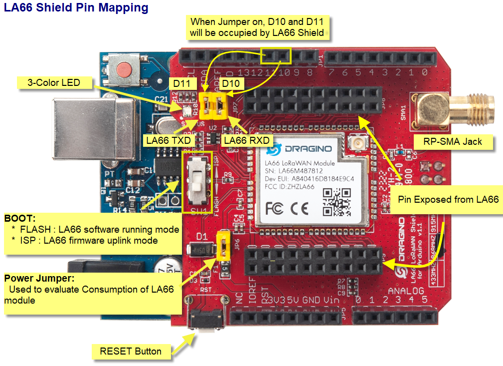
1. The LED lights up red when there is an upstream data packet
2. When the network is successfully connected, the green light will be on for 5 seconds
3. Purple light on when receiving downlink data packets
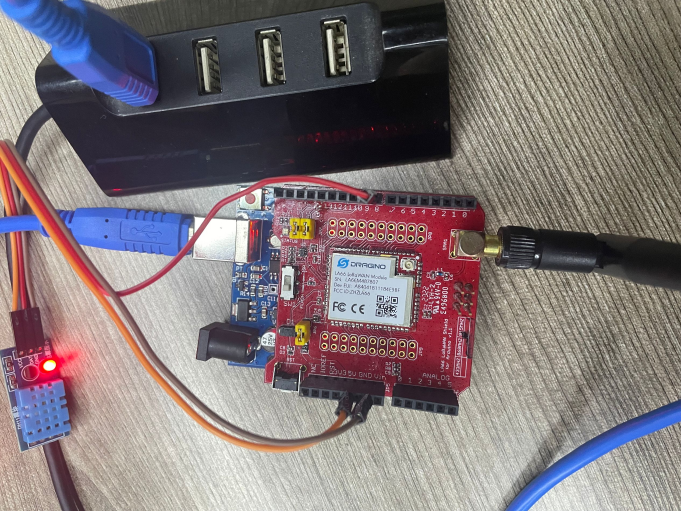
1.5 Example: Use AT Command to communicate with LA66 module via Arduino UNO.
Show connection diagram:
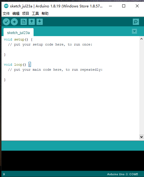
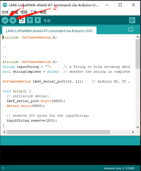
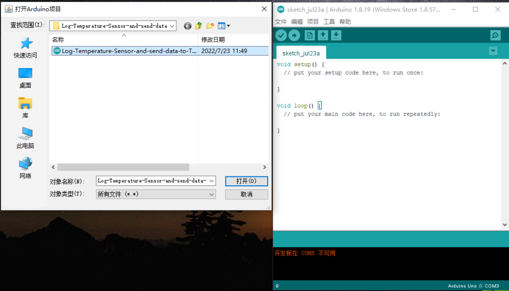
1. open Arduino IDE
2. Open project
LA66-LoRaWAN-shield-AT-command-via-Arduino-UNO source code link: https://www.dropbox.com/sh/cx0pspkwu62pr97/AAAbKh2ioPdZfSDtdDpooYqha?dl=0
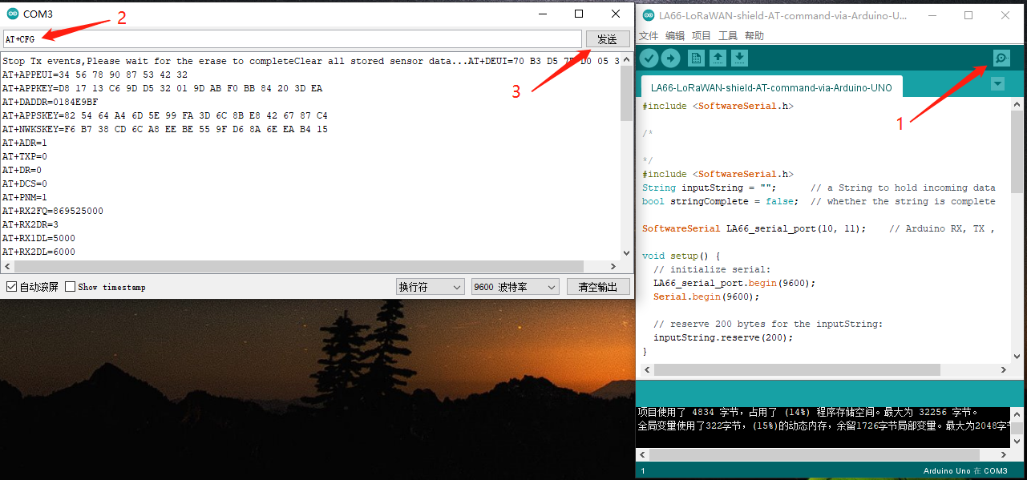
3. Click the button marked 1 in the figure to compile, and after the compilation is complete, click the button marked 2 in the figure to upload
4. After the upload is successful, open the serial port monitoring and send the AT command
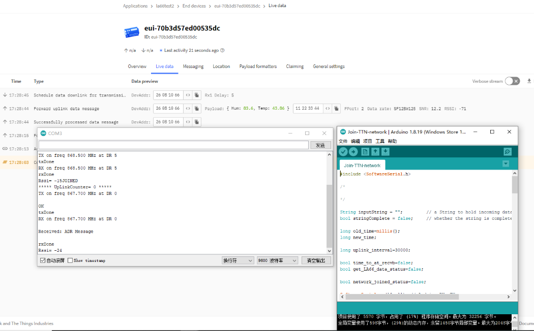
1.6 Example: Join TTN network and send an uplink message, get downlink message.
1. Open project
Join-TTN-network source code link: https://www.dropbox.com/sh/0sjyncafa0gjv00/AACC2m1orov-QHRkvH8-ddCka?dl=0
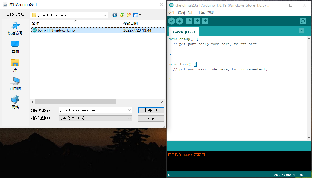
2. Same steps as 2.5,after opening the serial port monitoring, it will automatically connect to the network and send packets
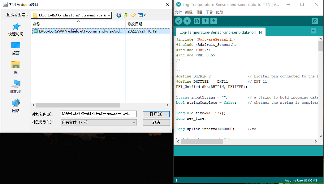
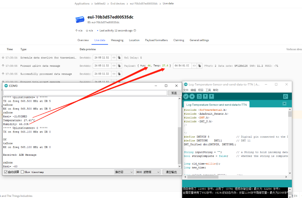
1.7 Example: Log Temperature Sensor(DHT11) and send data to TTN, show it in Node-RED.
1. Open project
Log-Temperature-Sensor-and-send-data-to-TTN source code link: https://www.dropbox.com/sh/0aagmrpec1lxmva/AABMXWVMSHG9dK1_Zv_7xOmCa?dl=0
2. Same steps as 2.5,after opening the serial port monitoring, it will automatically connect to the network and send packets
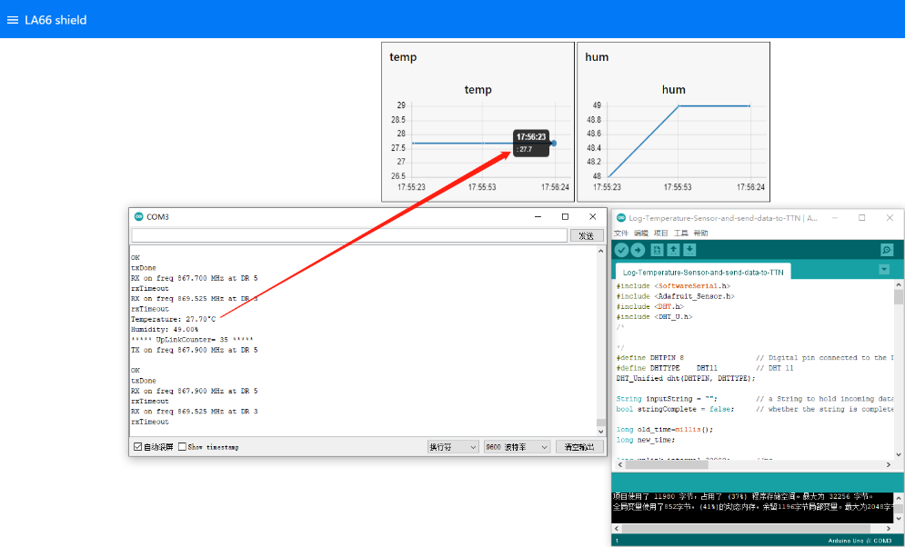
3. Integration into Node-red via TTNV3
For the usage of Node-RED, please refer to: http://8.211.40.43:8080/xwiki/bin/view/Main/Node-RED/
1.8 Upgrade Firmware of LA66 LoRaWAN Shield
1.8.1 Items needed for update
- LA66 LoRaWAN Shield
- Arduino
- USB TO TTL Adapter
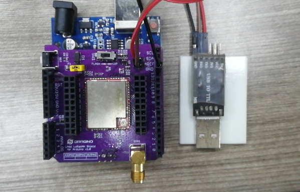
1.8.2 Connection
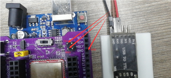
LA66 LoRaWAN Shield <-> USB TTL
GND <-> GND
TXD <-> TXD
RXD <-> RXD
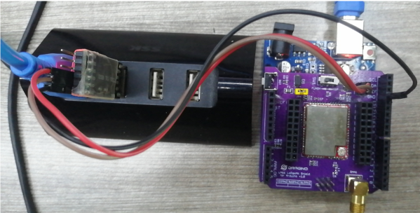
Put a jumper cap on JP6 of LA66 LoRaWAN Shield. ( the jumper is to power on LA66 module)
Connect USB TTL Adapter to PC after connecting the wires
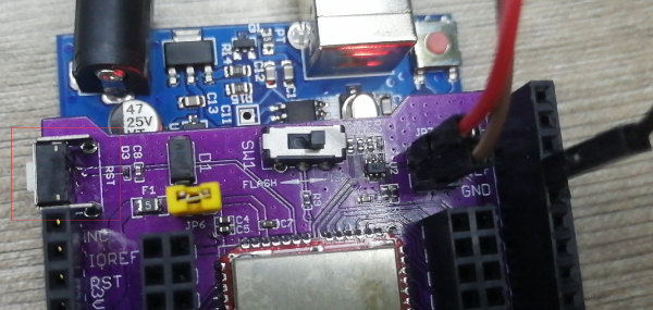
1.8.3 Upgrade steps
1. Switch SW1 to put in ISP position
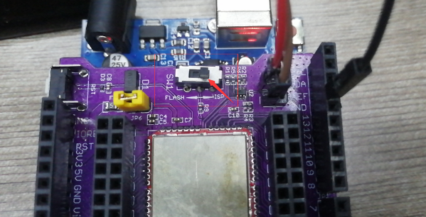
2. Press the RST switch once
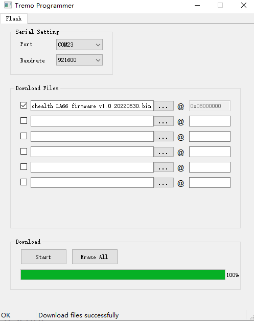
3. Open the Upgrade tool (Tremo Programmer) in PC and Upgrade
1. Software download link: https://www.dragino.com/downloads/index.php?dir=LSN50-LoRaST/Utility/LSN50N/

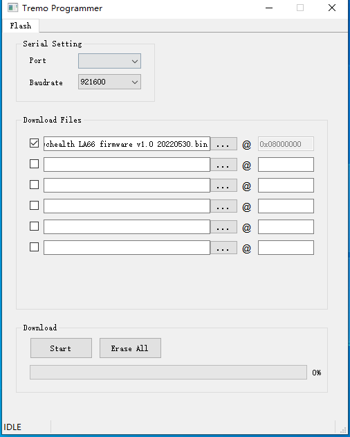
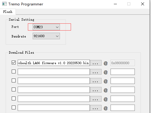
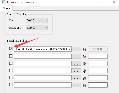
2. Select the COM port corresponding to USB TTL
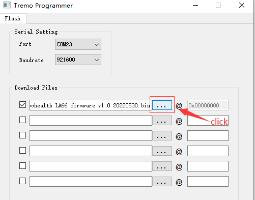
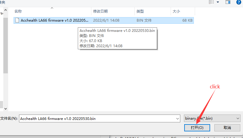
3. Select the bin file to burn
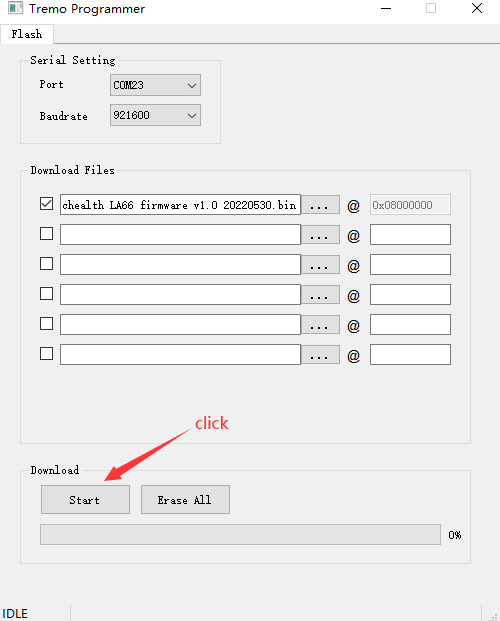
4. Click to start the download
5. Check update process
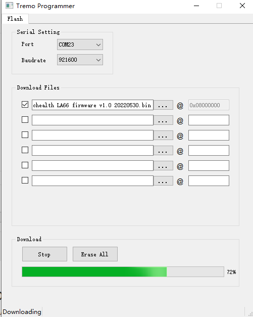
The following picture shows that the burning is successful
2. FAQ
2.1 How to Compile Source Code for LA66?
Compile and Upload Code to ASR6601 Platform :Instruction
3. Order Info
Part Number: LA66-LoRaWAN-Shield-XXX
XXX: The default frequency band
- AS923: LoRaWAN AS923 band
- AU915: LoRaWAN AU915 band
- EU433: LoRaWAN EU433 band
- EU868: LoRaWAN EU868 band
- KR920: LoRaWAN KR920 band
- US915: LoRaWAN US915 band
- IN865: LoRaWAN IN865 band
- CN470: LoRaWAN CN470 band
- PP: Peer to Peer LoRa Protocol
4. Reference
- Hardware Design File for LA66 LoRaWAN Shield : Download