LG01v2 -- LoRa Gateway User Manual
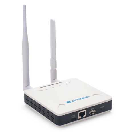
Table of Contents:
- 1. Introduction
- 2. Quick Start
- 3. Web Configure Pages
- 4. Build in Server
- 5. How to configure the Lora Gateway
- 6. How users can access LG01-V2 using serial USB
- 7. FAQ
- 8. Supports
- 9. Reference
- 10. Order Info
- 10. Manufacturer Info
- 11. FCC Warning
1. Introduction
1.1 What is LG01-V2
The LG01-V2 is an open-source single channel LoRa Gateway. It lets you bridge LoRa wireless network to an IP network via WiFi , Ethernet or Cellular Network (via Optional 4G module). The LoRa wireless allows users to send data and reach extremely long ranges at low data rates.
LG01-V2 supports remote management. System Integrator can easy to remote monitor the gateway and maintain it.
1.2 Specifications
Hardware System:
- CPU: Quad-core Cortex-A7 1.2Ghz
- RAM: 512MB
- eMMC: 4GB
Interface:
- 10M/100M RJ45 Ports x 1
- WiFi 802.11 b/g/n
Operating Condition:
- Work Temperature: -20 ~ 65°C
- Storage Temperature: -20 ~ 65°C
- Power Input: 5V, 2A, DC
1.3 Features
- Open Source Debian system
- Managed by Web GUI, SSH via WAN or WiFi
- Remote Management
- Auto-provisioning for batch deployment and management
- LoRa Gateway
- Built-in The Things Network local LoRaWAN server
- Built-in Node-Red local Application server
1.4 Block Diagram
1.5 LED Indicators
LG01-V2 has totally four LEDs, They are:
➢ Power LED: This RED LED will be solid if the device is properly powered
➢ ETH LED: This RGB LED will blink GREEN when the ETH port is connecting
➢ SYS LED: This RGB LED will show different colors in different states:
✓ SOLID GREEN: The device is alive with a LoRaWAN server connection.
✓ BLINKING GREEN: a) Device has internet connection but no LoRaWAN Connection. or b) Device is in booting stage, in this stage, it will BLINKING GREEN for several seconds and then with BLINKING GREEN together
✓ SOLID RED: Device doesn't have an Internet connection.
➢ WIFI LED: This LED shows the WIFI interface connection status.
1.6 Button Intruction
LG01-V2 has a black toggle button, which is:
➢ Long press 4-5s : the gateway will reload the Network and Initialize wifi configuration
LED status: ETH LED will BLINKIND BULE Until the reload is finished.
➢ Long press more than 10s: the gateway will restore the factory settings.
LED status: ETH LED will SOLID BULE Until the restore is finished.
2. Quick Start
The LG01-V2 supports network access via Ethernet or Wi-Fi connection and runs without a network.
In most cases, the first thing you need to do is make the LG01-v2 accessible to the network.
2.1 Connects to the network and accesses the gateway Web UI
2.1.1 connect the network.
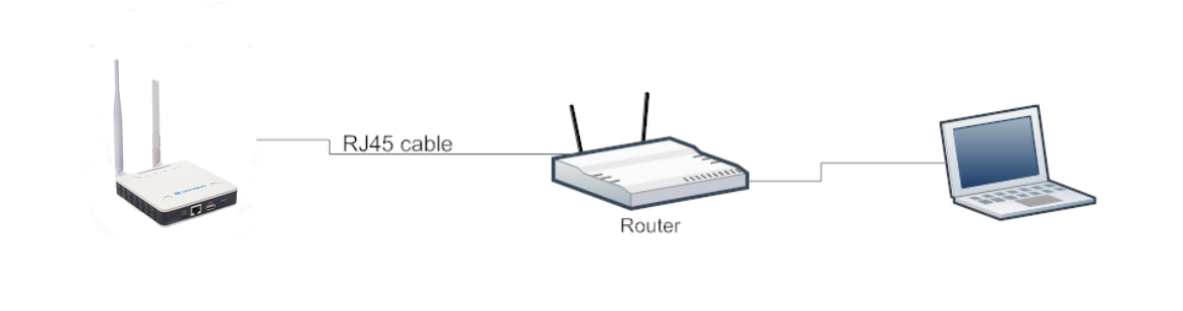
Method 1: Connect via Ethernet with DHCP IP from the router
Connect the LG01-V2 Ethernet port to your router and LG01-V2 can obtain an IP address from your router. In the router's management portal, you should be able to find what IP address the router has assigned to the LG01-V2.
You can also use this IP to connect.
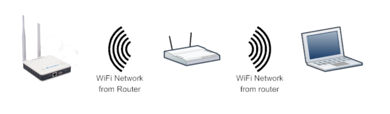
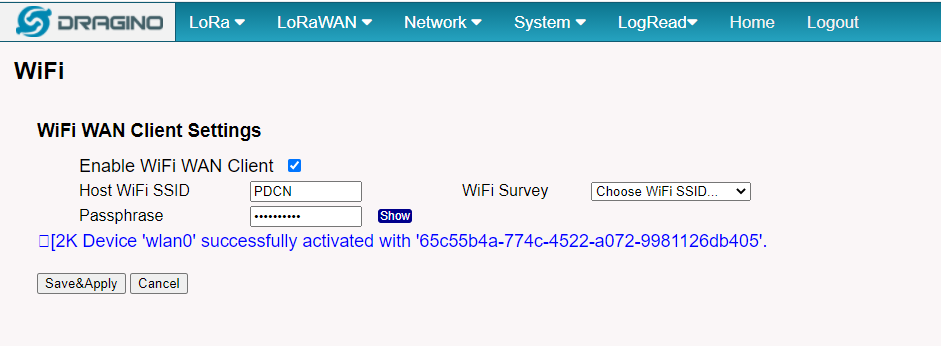
Method 2: Connect via WiFi with DHCP IP from the router
Fill in the WiFi information by checking the box and clicking Save&Apply
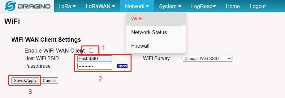
Wi-Fi configuration successful
3. Web Configure Pages
3.1 Home
Shows the system running status:

3.2 Network Settings
3.2.1 Network --> WiFi

3.4.2 Network --> System Status

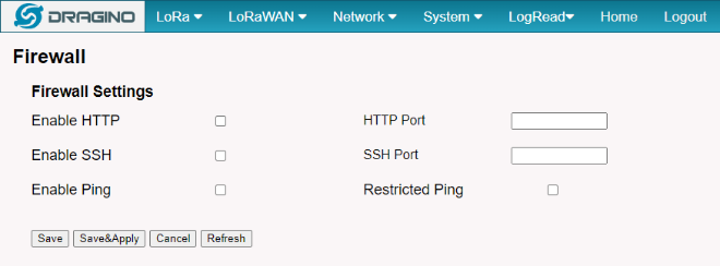
3.4.3 Network --> Firewall
3.5 System
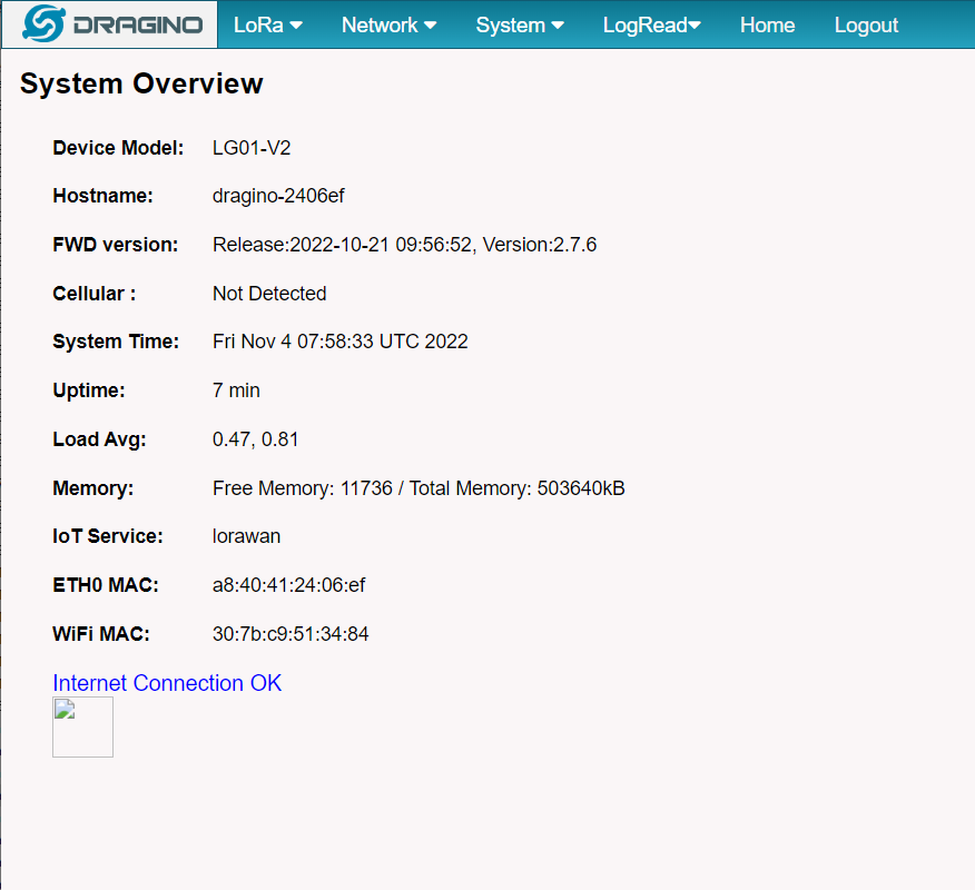
3.5.1 System --> System Overview
Shows the system info:
3.5.2 System --> Backup/Restore

4. Build in Server
The default factory version of LG01-V2 is installed with the built-in Applicant server: Node-Red

Note:
Path: System --> Built-in Server
Troubleshooting:
1. URL does not jump properly
For the Node-Red, you can use the local IP address and the port is 1880 to access it.
4.1 Application Server -- Node-Red
You can access the gateway's built-in AS server of Node-Red via the URL(http://<hostname>:1880 or http://<local-IPV4-address>) in your browser.
Such as http://dragino-54ff12:1880 or http://<Local-IPV4-Address>
5. How to configure the Lora Gateway
5.1 Access the Lora configuration page
Users can access the Lora configuration page by running the following command, then select the option ''serial port setup":
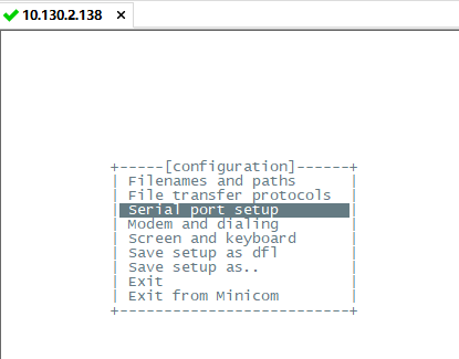
And then, change the setting:
Note: Enter the corresponding letter to change the configuration, like A,B,C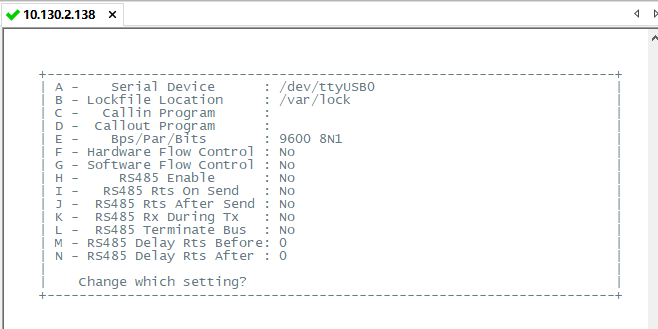
Enter AT+CFG in the interface to get the configuration,
5.2 Example: LG01-V2 Peer-to-Peer
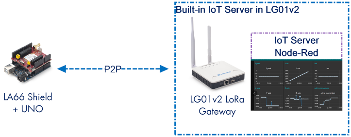
The user can run the AT command to set the LG01-V2 RX window always open as a Receiver, The LG01-V2 can display the received data in the built-in server Node-Red, Here are the specific steps:
Prerequisites: The configuration of LG01-V2 and LA66 Shield must match and the LA66 Shield firmware is LA66 Peer-to-Peer firmware, users can use AT+CFG to check all configurations.
Log Temperature Sensor(DHT11) and send data to LG01v2, show it in Node-RED.
LG01-V2 as Receiver: (configured as AT+RXMOD=65535,2)
LA66 Shield as Sender:
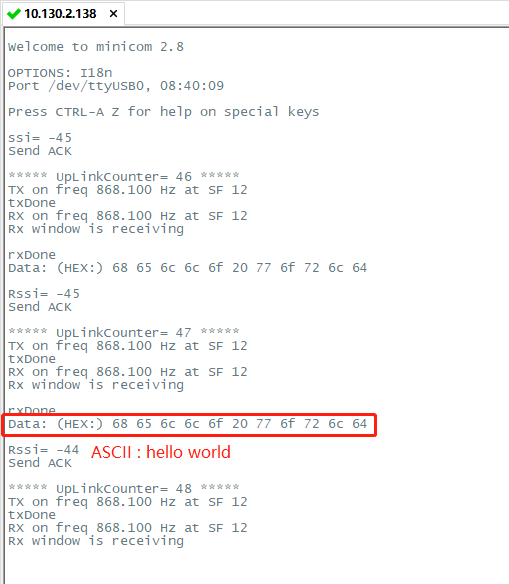
After the above configuration is complete, users can send test simulation data to check whether the configuration is correct, In LA66 sheild serial console send:(AT+SEND=1,hello world,2,3).
When LG01-V2 replies with ACK when it receives a packet sent by LA66 sheild.
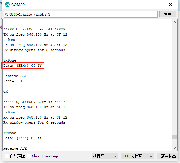
In the real-time log of LG01-V2:
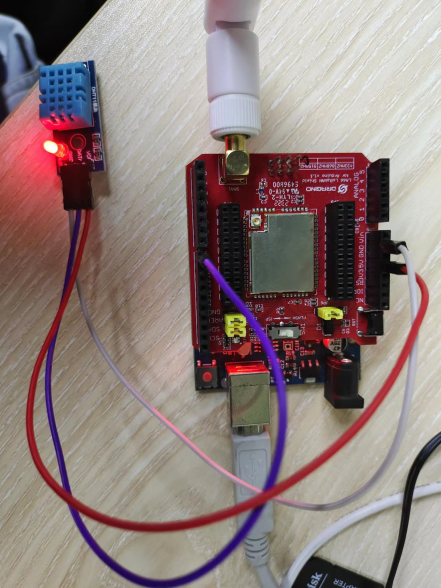
Hardware Connection
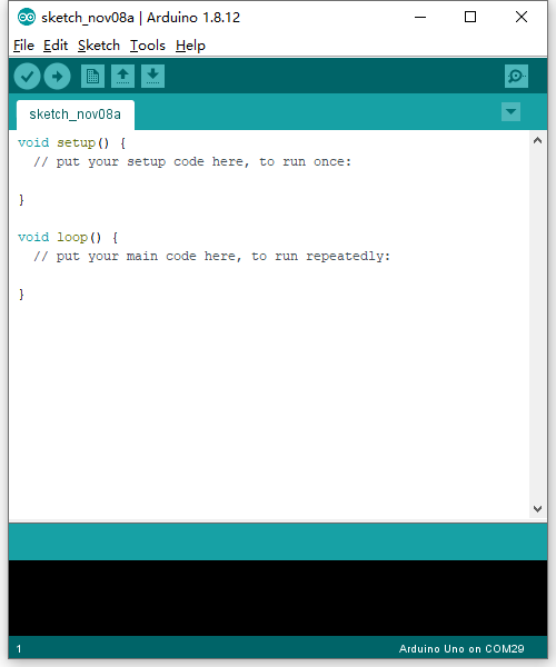
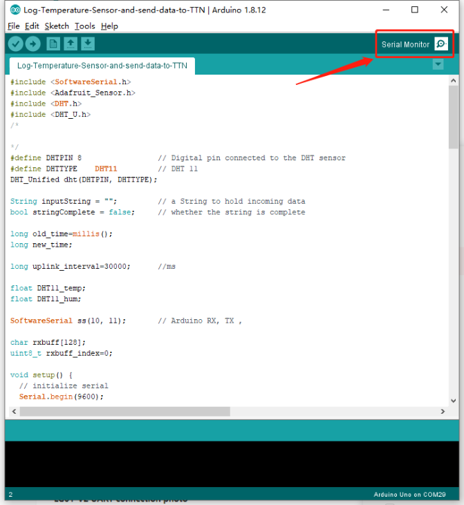
1. open Arduino IDE
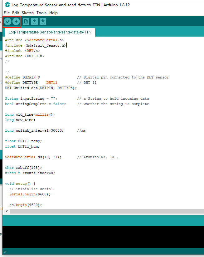
2. Open project
Users can download Arduino files from this link:
Then click Compile and Upload to LA66 Shield,
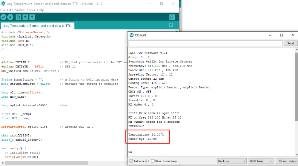
3. Open the Serial Monitor to check the LA66 Shield data
The LA66 Shield reads the temperature and humidity data from the sensor and sends it to LG01V2,
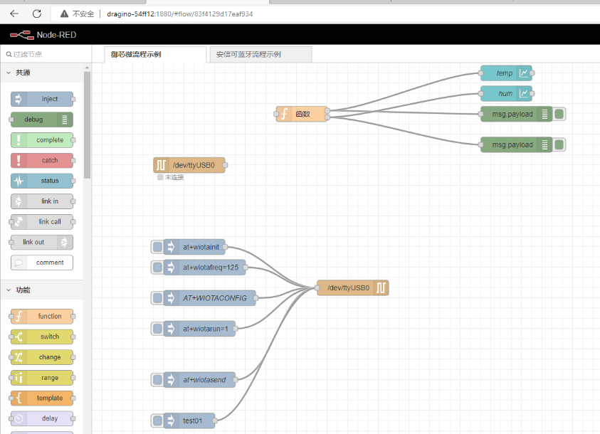
4. Import the flow to the built-in server on LG01v2
Users can import this example in Node-Red:
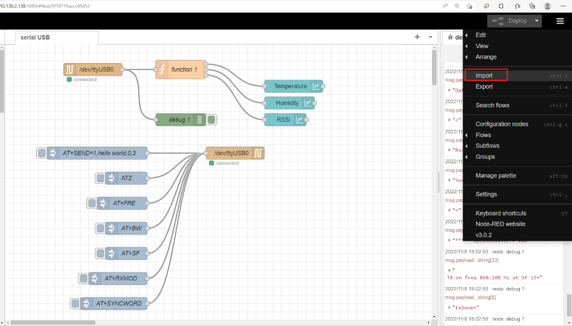
The temperature and humidity chart is displayed in the built-in node-red UI
Browser input: LG01-V2 IP address:1880/ui/

6. How users can access LG01-V2 using serial USB
USB TTL to LG01-V2 Connection:
Port 1 of the UART on the LG01-V2 is GND
LG01-V2 UART connection photo
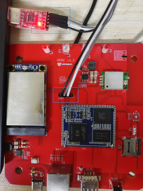
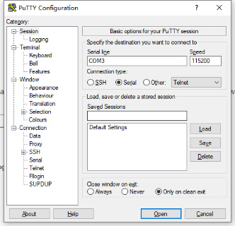
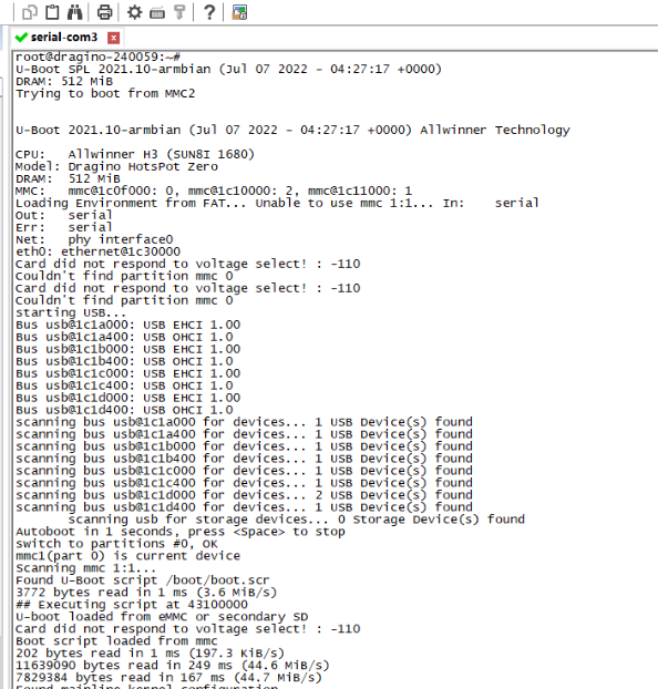
In the PC, you can use the serial port tool(such as putty in Windows), you need to set the serial baud rate to 115200 to access the serial console for LG01v2. LG01v2 will output system info once power on as below:
7. FAQ
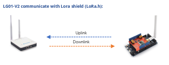
7.1 How does LG01-V2 communicate with Lora shield (LoRa.h)
This example describes how to use LG01-V2, LoRa Shield to set up a LoRa network
Prerequisites: The configurations of LG01-V2 and Lora shield must match
LG01-V2 configuration:
Lora shield configuration:
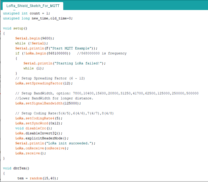
Lora Shield example: ,
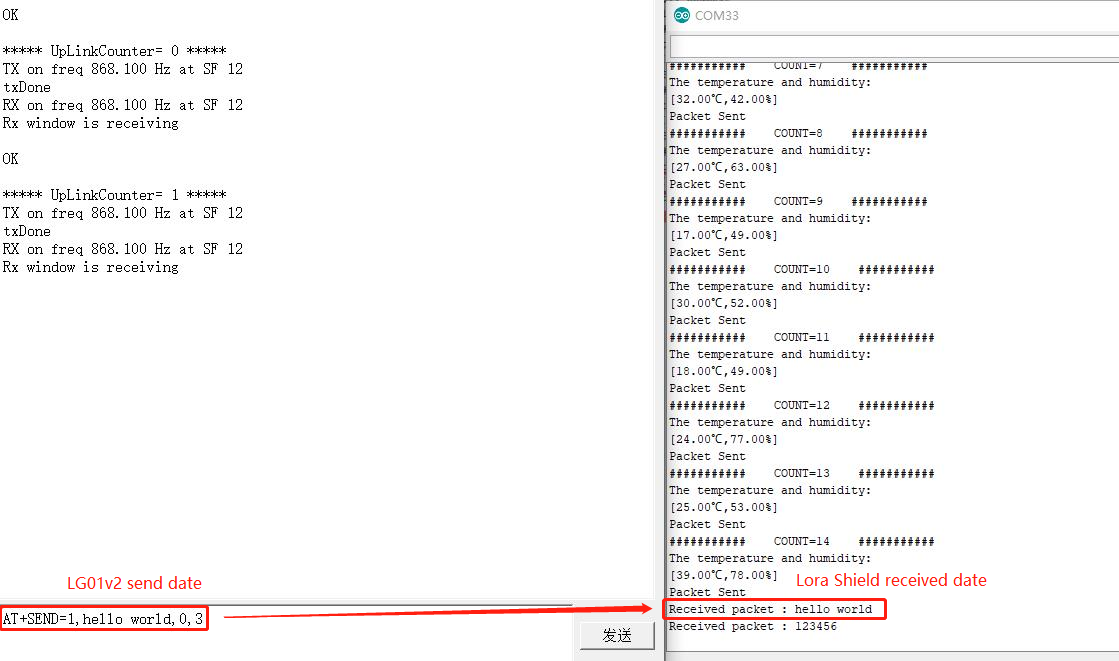
Test LG01-V2 to receive Lora Shield data:
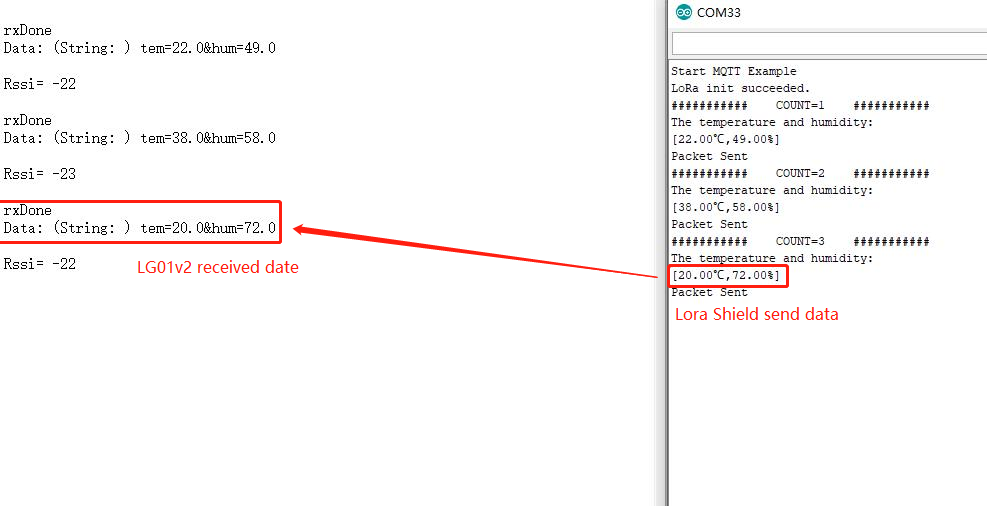
Test the LG01-V2 to send data:
8. Supports
If you are experiencing issues and can't solve them, you can send mail to support@dragino.com.
With your question as detailed as possible. We will reply and help you in the shortest.
9. Reference
- Install Tago Core: Refer Install Tago Core in LPS8v2 in Instruction.
- Advance OS Reference Guide for LPS8v2.
10. Order Info
LPS8v2-XXX-YYY
XXX: Frequency Band
- AS923: LoRaWAN AS923 band
- AU915: LoRaWAN AU915 band
- EU868: LoRaWAN EU868 band
- KR920: LoRaWAN KR920 band
- US915: LoRaWAN US915 band
- IN865: LoRaWAN IN865 band
YYY: 4G Cellular Option
- E: EMEA, Korea, Thailand, India.
- A: North America/ Rogers/AT&T/T-Mobile.
- AU: Latin America, New Zeland, Taiwan
- J: Japan, DOCOMO/SoftBank/ KDDI
More info about valid bands, please see EC25-E product page.
10. Manufacturer Info
Shenzhen Dragino Technology Development co. LTD
Room 202, Block B, BCT Incubation Bases (BaoChengTai), No.8 CaiYunRoad
LongCheng Street, LongGang District ; Shenzhen 518116,China
11. FCC Warning
This equipment has been tested and found to comply with the limits for a Class B digital device, pursuant to Part 15 of the FCC Rules. These limits are designed to provide reasonable protection against harmful interference in a residential installation. This equipment generates uses and can radiate radio frequency energy and, if not installed and used in accordance with the instructions, may cause harmful interference to radio communications. However, there is no guarantee that interference will not occur in a particular installation. If this equipment does cause harmful interference to radio or television reception, which can be determined by turning the equipment off and on, the user is encouraged to try to correct the interference by one or more of the following measures:
-- Reorient or relocate the receiving antenna.
-- Increase the separation between the equipment and receiver.
-- Connect the equipment into an outlet on a circuit different from that to which the receiver is connected.
-- Consult the dealer or an experienced radio/TV technician for help.
Changes or modifications not expressly approved by the party responsible for compliance could void the user's authority to operate the equipment.
The antenna(s) used for this transmitter must be installed to provide a separation distance of at least 20 cm from all persons and must not be co-located or operating in conjunction with any other antenna or transmitter.
)))