Notes for AWS-IoT-Core
Table of Contents:
- 1. Introduction
- 2. Gateway Setup Instruction
- 2.1 Step 1: Sign up for an AWS account and select the area
- 2.2 Step 2: Add an IAM role
- 2.3 Step 3: Add gateway
- 2.4 Step 4: Get a unique Gateway ID in the gateway
- 2.5 Step 5: Configure the gateway and Creation gateway certificates
- 2.6 Step 6: Add the configuration to the Gateway Web UI.
- 2.7 Step 8: Check the last upLink received
- 2.8 Trouble Shooting
- 1. WS connect failed: NET - Failed
- 2. gateway station log displays "Recv failed: SSL - The peer notified us that The connection is going to be closed".
- 3. gateway station log displays "Failed to retrieve TCURI from CUPS: (400) Bad Request".
- 4. gateway station log displays "[4] Send failed: NET - Connection was reset by peer"
- 5. gateway station log displays "Malformed CUPS response: URI segments lengths (227) exceed available data (199)"
- 3. Add wireless device
- 4. Format a notification by using an AWS Lambda function
- 4.1 Introduction
- 4.2 Approach A: DECODING BINARY PAYLOADS
- 4.3 Approach B Create an AWS Lambda function that sends a text message
- 4.3.1 Step 1 : To create an AWS Lambda function that sends a text message
- 1. Create a new AWS Lambda function.
- 2. Modify the blueprint code to format and send an Amazon SNS notification.
- 3. In a new window, look up the Amazon Resource Name (ARN) of your Amazon SNS topic from the tutorial about how to Send an Amazon SNS notification.
- 4. Create a test case for your Lambda function.
- 4.3.2 Step 2 : Create Rule with Lambda function
- 4.3.1 Step 1 : To create an AWS Lambda function that sends a text message
- 5. For End Node
- 6. Trouble Shooting
- 7. Reference
1. Introduction
The Dragino LoRaWAN gateway can communicate with Amazon LoRaWAN Network Server:
Below list of the support products and Requirements:
1. LoRaWAN Gateway model: LIG16, LG308, DLOS8 LPS8
2. Firmware version since:lgw--build-v5.4.1614945073
What you'll learn in this tutorial
1. How to register a gateway with AWS
2. How to register an end node with AWS
3. How to accept payload date with AWS
2. Gateway Setup Instruction
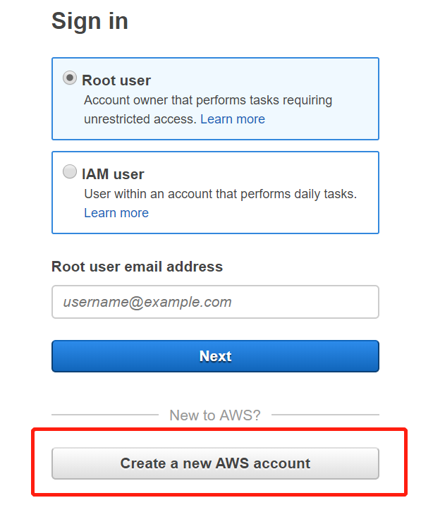
2.1 Step 1: Sign up for an AWS account and select the area
Sign up for an AWS account
Select area
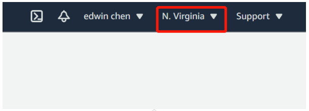
Note: Currently, AWS IoT Core for LoRaWAN is available today in US East (N. Virginia) and Europe (Ireland) Regions. if you are not in either of these areas, their options will not affect your usage.
2.2 Step 2: Add an IAM role
To add the IAM role to allow the Configuration and Update Server (CUPS) to manage gateway credentials:
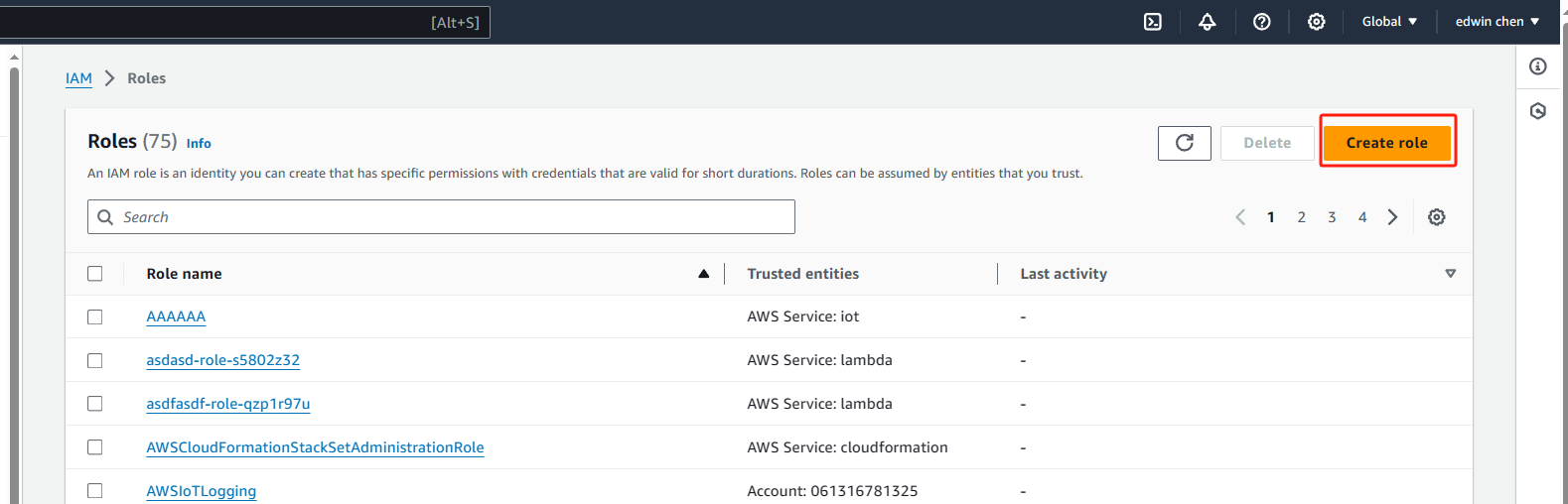
1. Open the Roles hub of the IAM console and choose Create role.
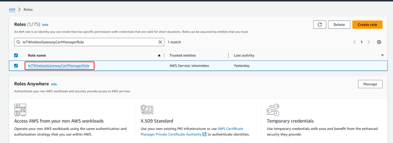
2. If you think that you might have already added the IoTWirelessGatewayCertManagerRole role, in the search bar, enter IoTWirelessGatewayCertManagerRole.
If you see an IoTWirelessGatewayCertManagerRole role in the search results, you have the necessary IAM role. You can leave the procedure now.
If the search results are empty, you don't have the necessary IAM role. Continue the procedure to add it.
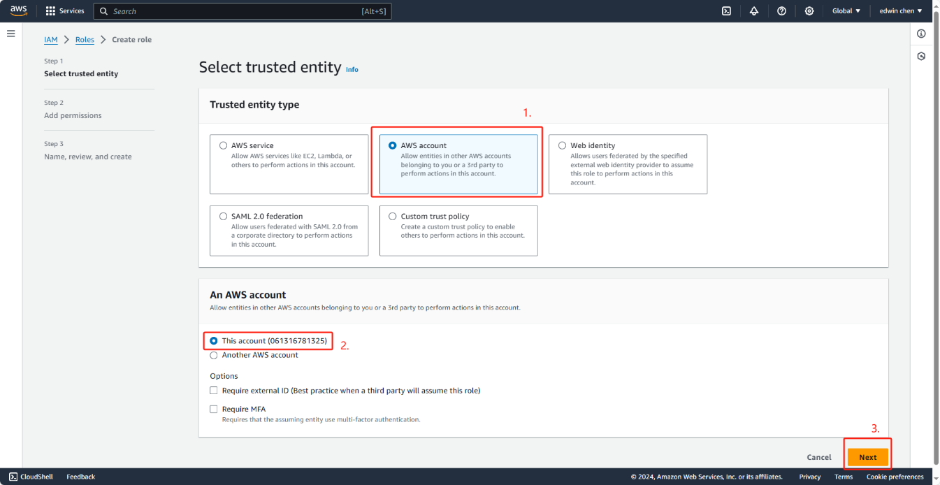
3. In Select type of trusted entity, choose Another AWS account.
4. In Account ID, enter your AWS account ID and then choose Next: Permissions.
5. In the search box, enter AWSIoTWirelessGatewayCertManager.
6. In the list of search results, select the policy named AWSIoTWirelessGatewayCertManager.
7. Choose Next: Tags, and then choose Next: Review.
8. In Role name, enter IoTWirelessGatewayCertManagerRole, and then choose to Create role.
9. To edit the new role, in the confirmation message, choose IoTWirelessGatewayCertManagerRole.
10. In Summary, choose the Trust relationships tab and then choose Edit trust relationship.
11. In the Policy Document, change the Principal property to look like this example.
"Principal": {
"Service": "iotwireless.amazonaws.com"
},
After you change the Principal property, the complete policy document should look like this example.
{
"Version": "2012-10-17",
"Statement": [
{
"Effect": "Allow",
"Principal": {
"Service": "iotwireless.amazonaws.com"
},
"Action": "sts:AssumeRole",
"Condition": {}
}
]
}
12. To save your changes and exit, choose Update Trust Policy. Note: You've now created the IoTWirelessGatewayCertManagerRole. You won't need to do this again.
start create role
Choose this account
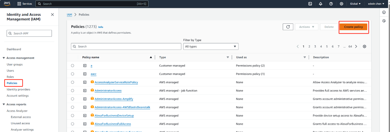
start Create policy
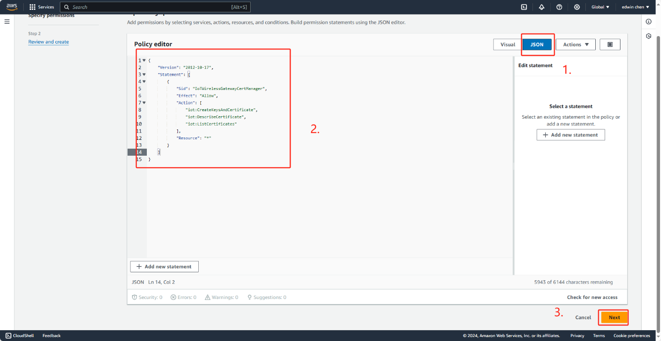
Modifying the policy editor
Change policy Document
{
"Version": "2012-10-17",
"Statement": [
{
"Sid": "IoTWirelessGatewayCertManager",
"Effect": "Allow",
"Action": [
"iot:CreateKeysAndCertificate",
"iot:DescribeCertificate",
"iot:ListCertificates"
],
"Resource": "*"
}
]
}
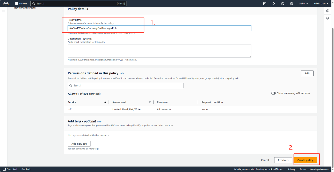
In role name,enter AWSIoTWirelessGatewayCertManagerRole,and then choose Create role.
To edit the_new role
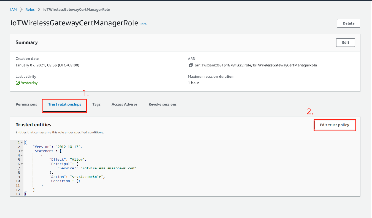
Choose Edit trust policy.
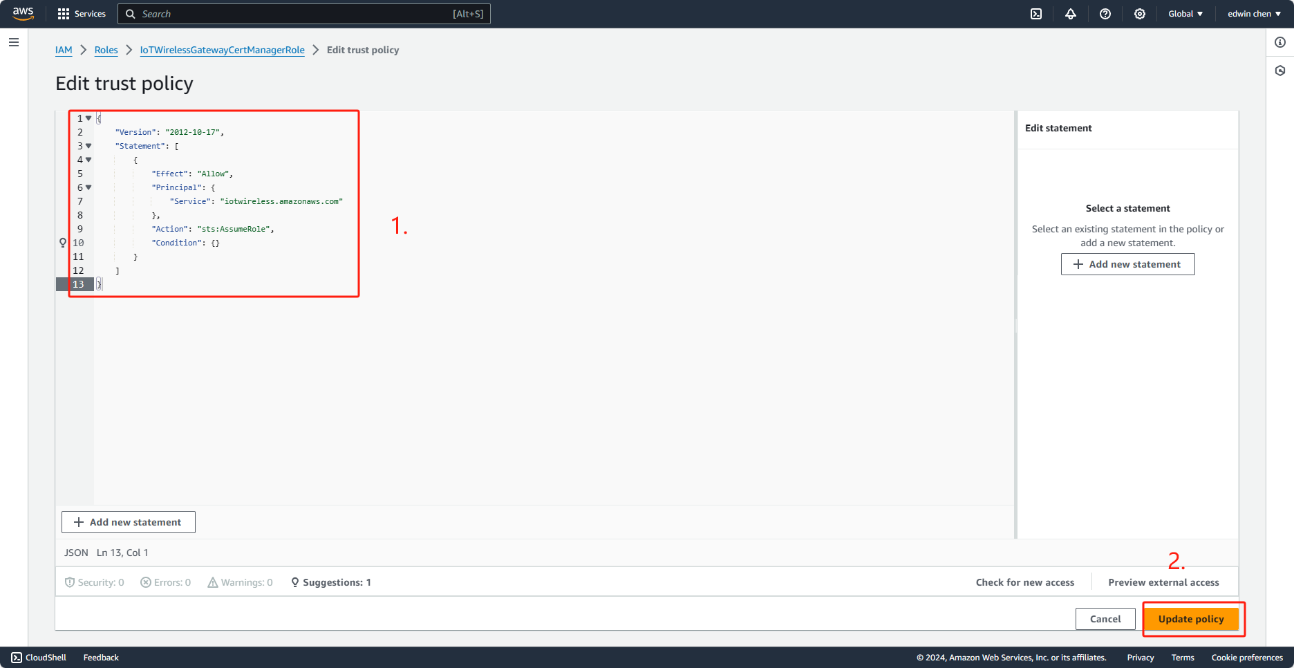
Change role Document
"Version": "2012-10-17",
"Statement": [
{
"Effect": "Allow",
"Principal": {
"Service": "iotwireless.amazonaws.com"
},
"Action": "sts:AssumeRole",
"Condition": {}
}
]
}
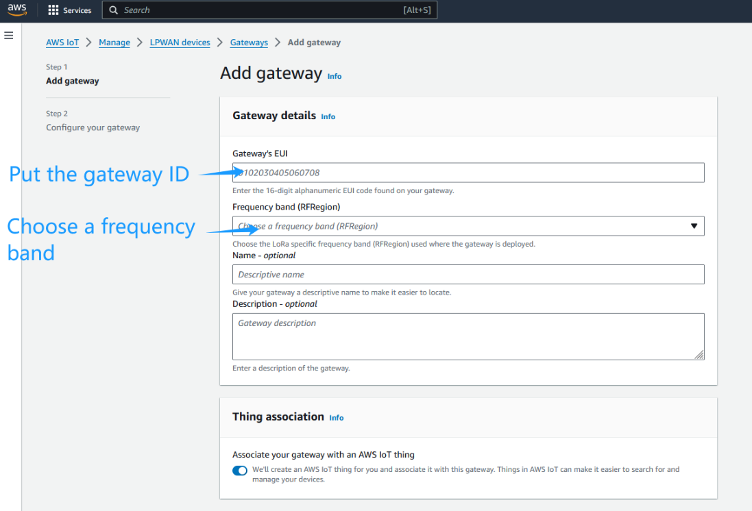
2.3 Step 3: Add gateway
Locate IoT Core in the AWS Service Control Panel, and locate the Wireless Connection in the IoT Core Control Panel to start adding the Gateway
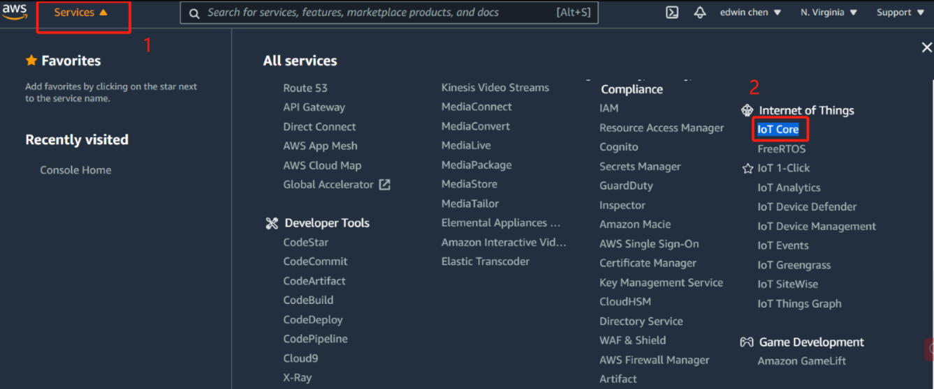
Locate IoT Core in the AWS Service Control Panel
locate the Wireless Connection in the IoT Core Control Panel
2.4 Step 4: Get a unique Gateway ID in the gateway
Every gateway has a Gateway ID, which can be found on LoRaWAN -- Basic Station page.
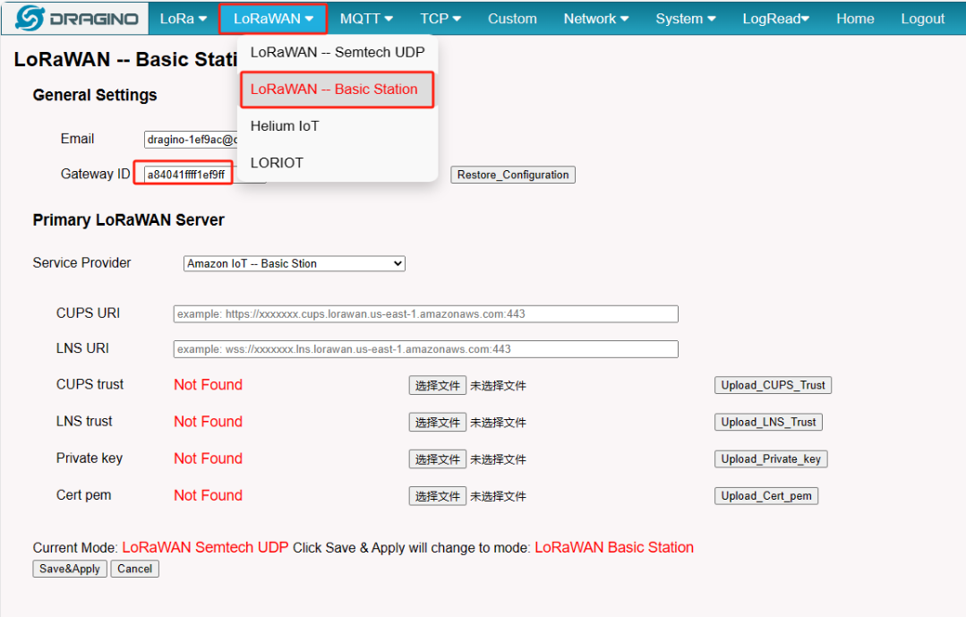
Gateway ID
Note: User must use the Gateway ID of the LoRaWAN -- Basic Station page as the EUI
Notice: In the latest firmware. the AWS-IoT configured page is under the LoRaWAN Basic Station page.
LoRaWAN Basic Station
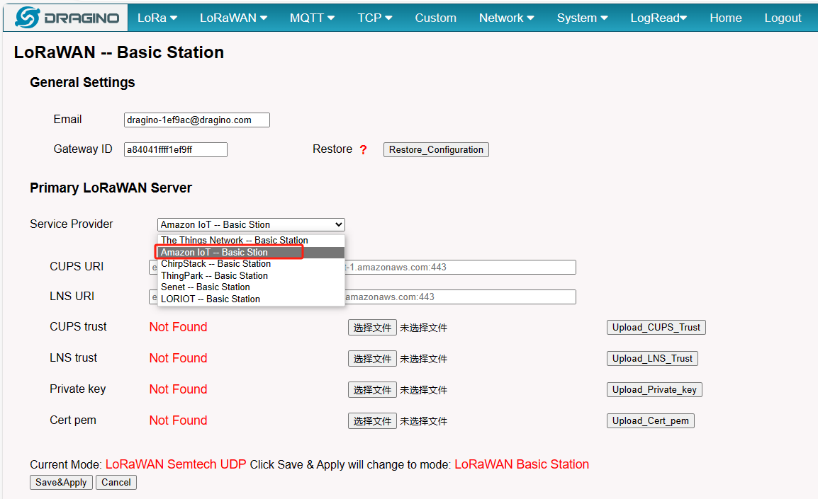
2.5 Step 5: Configure the gateway and Creation gateway certificates
Configure the gateway and Creation gateway certificates
Configure the gateway
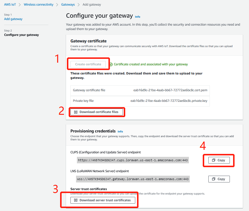
Creation gateway certificates
Note: User Make sure the name of the downloaded file remains the same.
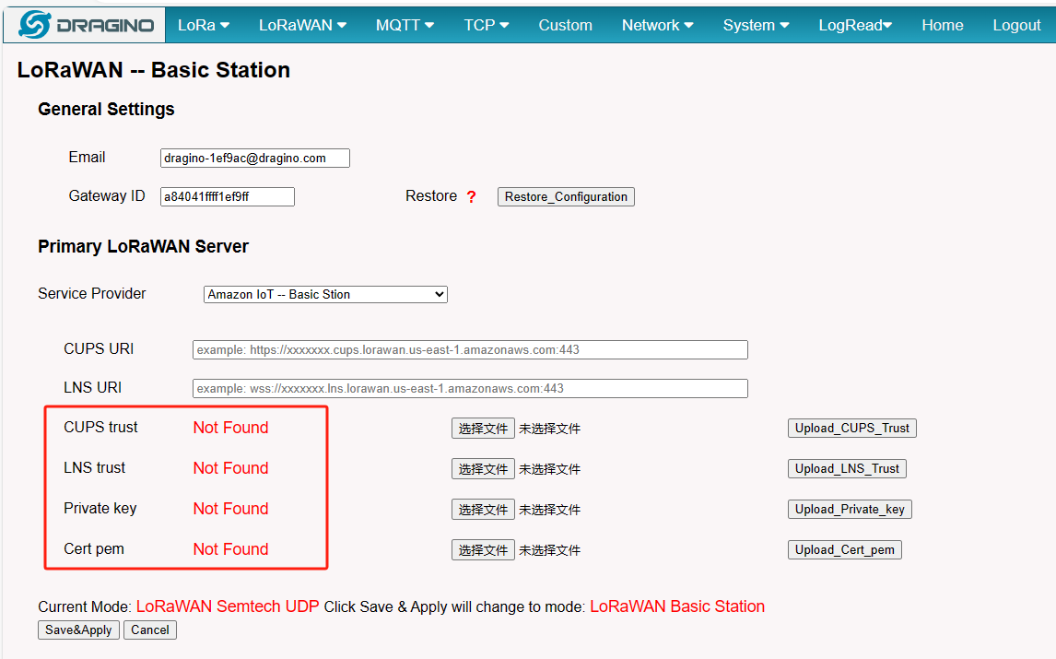
2.6 Step 6: Add the configuration to the Gateway Web UI.
user returns to your gateway, and start adding the three file they got to the gateway.
Configure the gateway
if the user Upload successfully you will see:
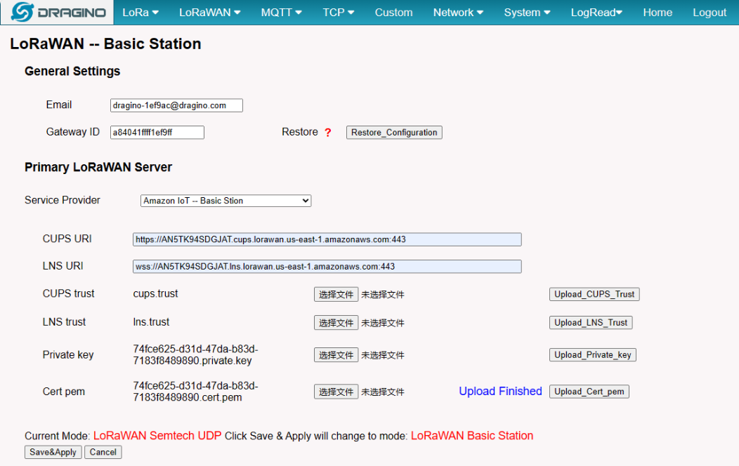
Uploaded successfully
Notice: User must select the correct Upload on the suffix name, otherwise the upload fails.
Notice: After the user hits "Save&Apply", the gateway will start Station mode on its own.
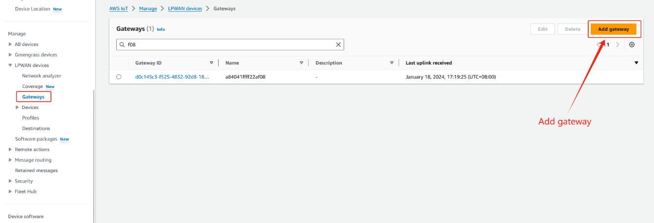
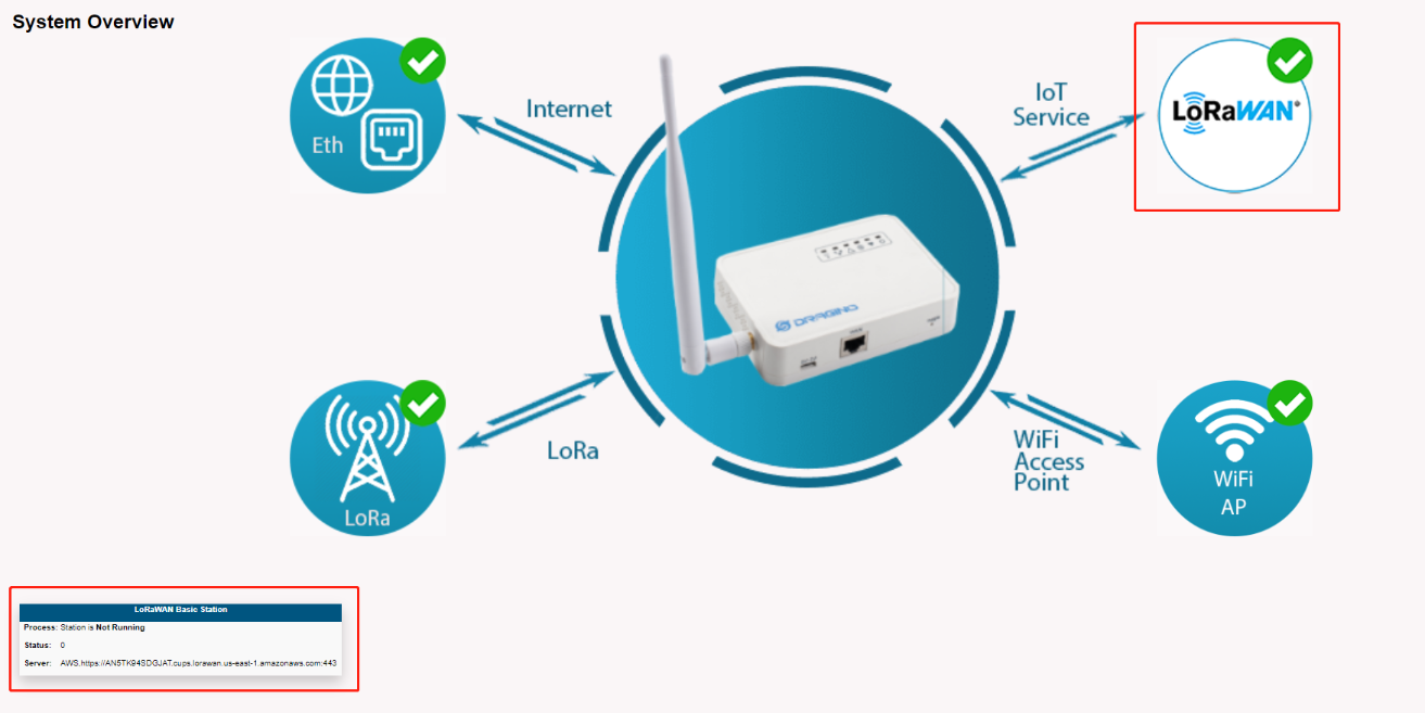
2.7 Step 8: Check the last upLink received
After the above settings, the gateway should be able to connect, the figure below shows the data of the Last upLink received
On the gateway Web UI
On the AWS console
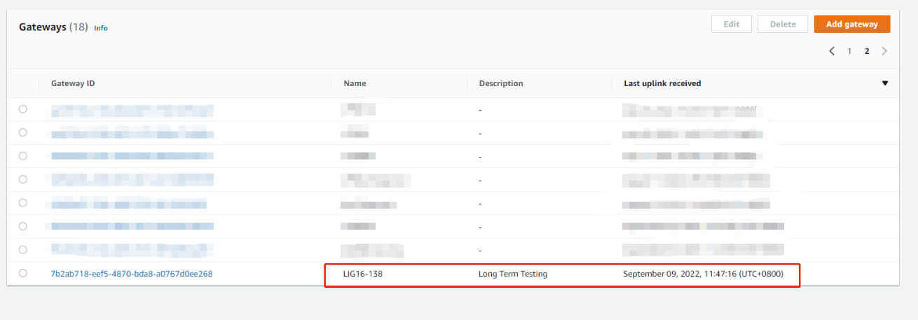
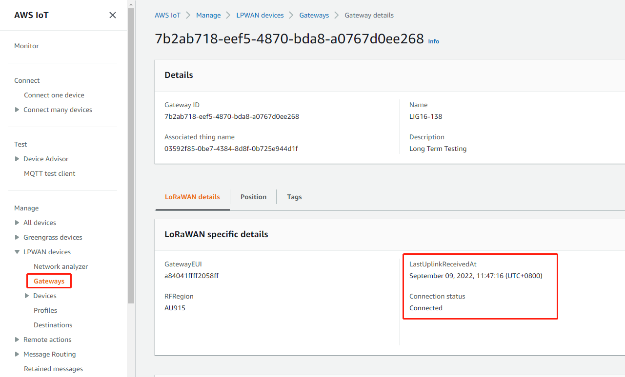
UpLink received
2.8 Trouble Shooting
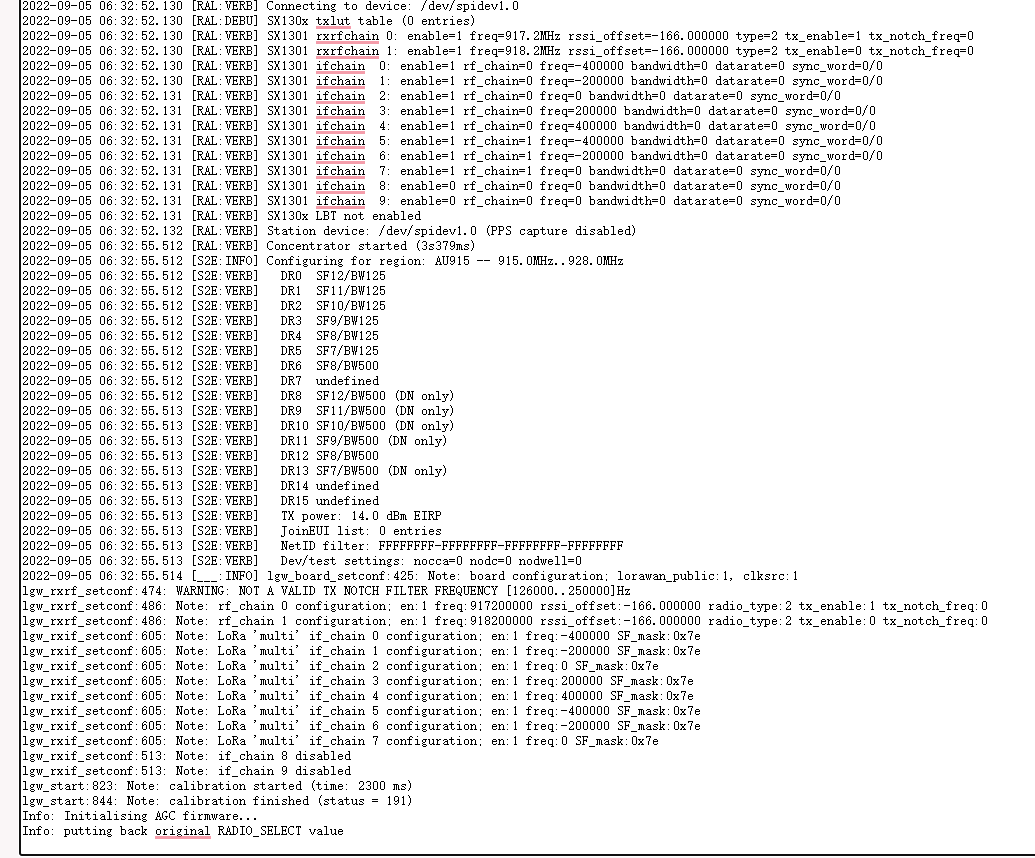
In normal cases, the logs of the gateway station are as follows:
1. WS connect failed: NET - Failed
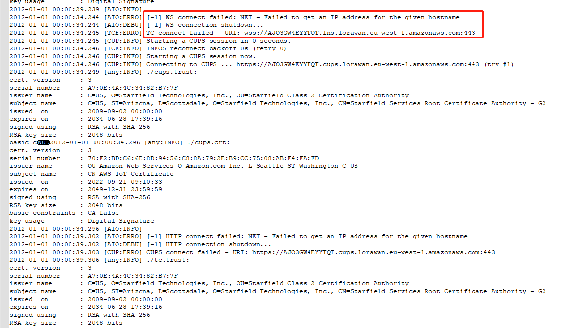
The log output indicates that the gateway was unable to resolve to an IP address from the domain name and then connect to the AWS lns server.
Here is the advice:
1). Whether the gateway is registered cycle to AWS multiple times?
2). Check if the gateway's EUI is the same as the AWS's
3). Change the gateway EUI and use the new EUI to register and connect the AWS.
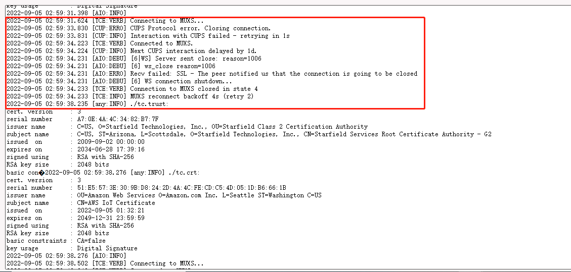
2. gateway station log displays "Recv failed: SSL - The peer notified us that The connection is going to be closed".
In this case, the user needs to check whether the Gateway ID matches the GatewayEUI on AWS IoT Core.
If the configuration is incorrect, user can first click "Restore_Configuration" and then reconfigure it.
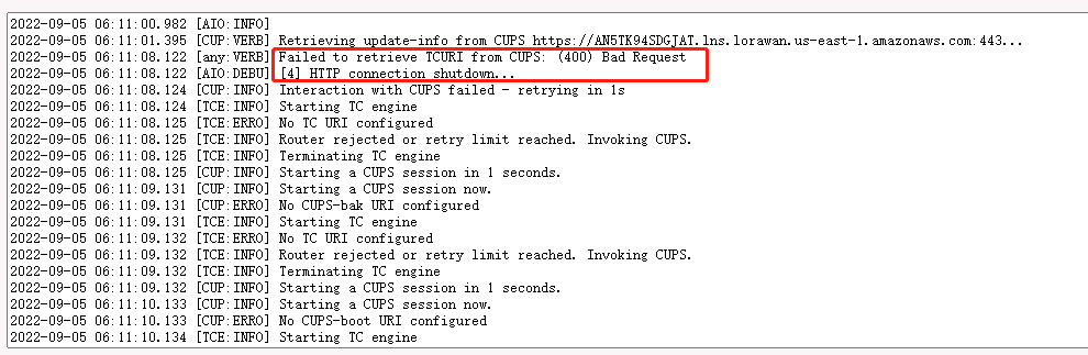
3. gateway station log displays "Failed to retrieve TCURI from CUPS: (400) Bad Request".
In this case, the user needs to check whether the CUPS URI matches the CUPS URI on AWS IoT Core.
It is recommended to re-check the configuration by following Step 5 in the wiki.
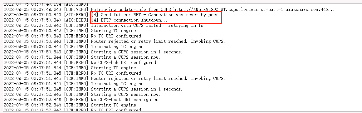
4. gateway station log displays "[4] Send failed: NET - Connection was reset by peer"
If the following information is displayed in the gateway station log, it indicates that the station version is too early and the configuration file is missing,
Users need to upgrade the firmware of the gateway. users can download the latest firmware from this link : lgw--build-v5.4.1661158991-20220822-1704
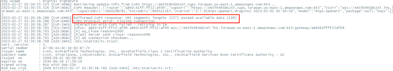
5. gateway station log displays "Malformed CUPS response: URI segments lengths (227) exceed available data (199)"
In this case, the user needs to check whether the Gateway ID matches the GatewayEUI on AWS IoT Core.
3. Add wireless device
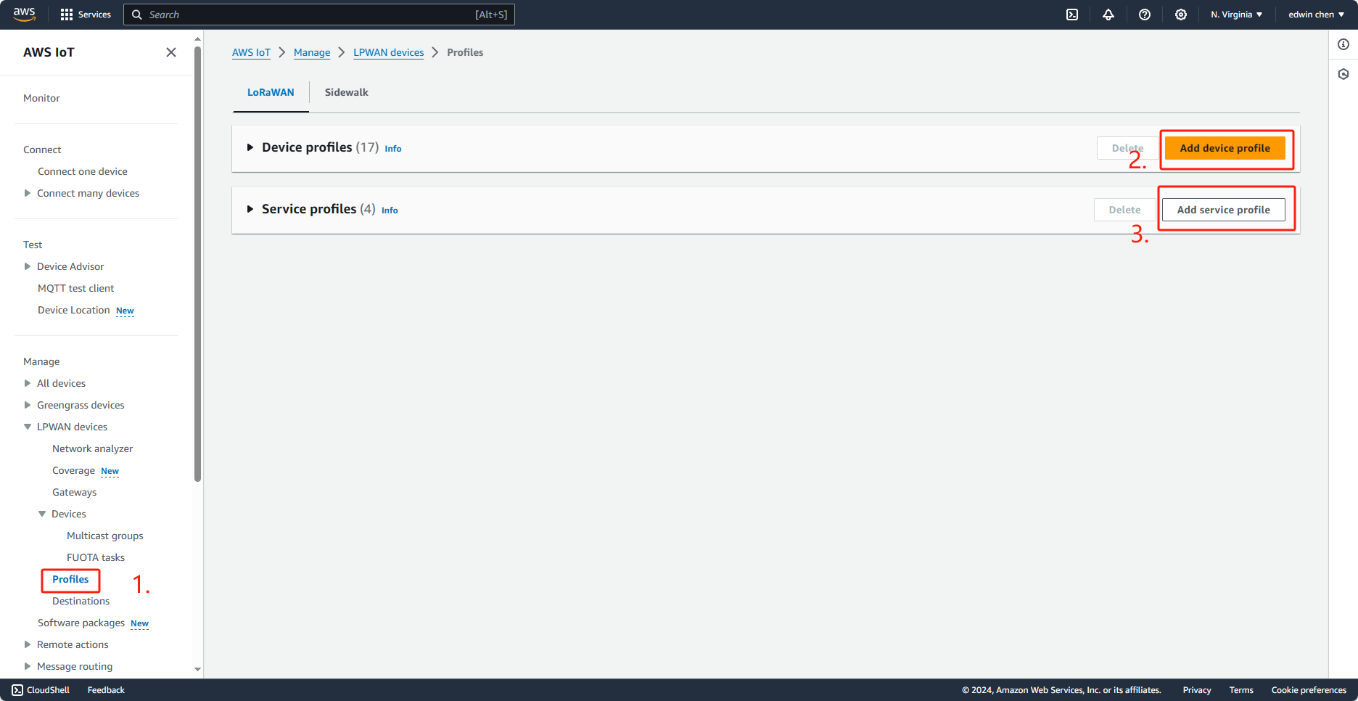
3.1 step 1 : Add device profile
3.1.1 CREATE DEVICE PROFILE
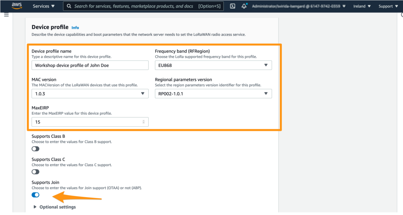
select profile in the Control Panel and add configuration adn service files.the device's configuration paranmeters depend on the LoRaWAN specification it uses.The configuration parameters are found in the device's documentation or on the device itself.
Add device profile
Provide device data
Device profile name : a descriptive name of your choice for this profile, e.g. “Workshop device profile of ”
Frequency band (RFRegion) : please select a frequency band your device and gateway will be using. For most European countries EU868 is a right choice. For USA US915 is a right choice. If in doubt, you can review a regional parameters document, section “1.2 Quick cross reference table”.
MAC version : this parameter should specify the most recent version of LoRaWAN specification supported by your device. Unless device documentation states otherwise, please select 1.0.3.
Regional parameters version: please select RP002-1.0.1, unless specified otherwise in your device documentation
MaxEIRP : please enter the default value 15
Supports class : please select class A, unless you are aware of specific requirements to use classes B and C and your device supports it
device profile
Notice : See the documentation for more information: https://docs.aws.amazon.com/iot/latest/developerguide/connect-iot-lorawan-define-profiles.html
3.1.2 CREATE SERVICE PROFILE
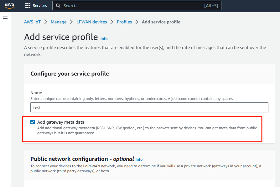
Select “Profiles” view and click on “Add service profile”.
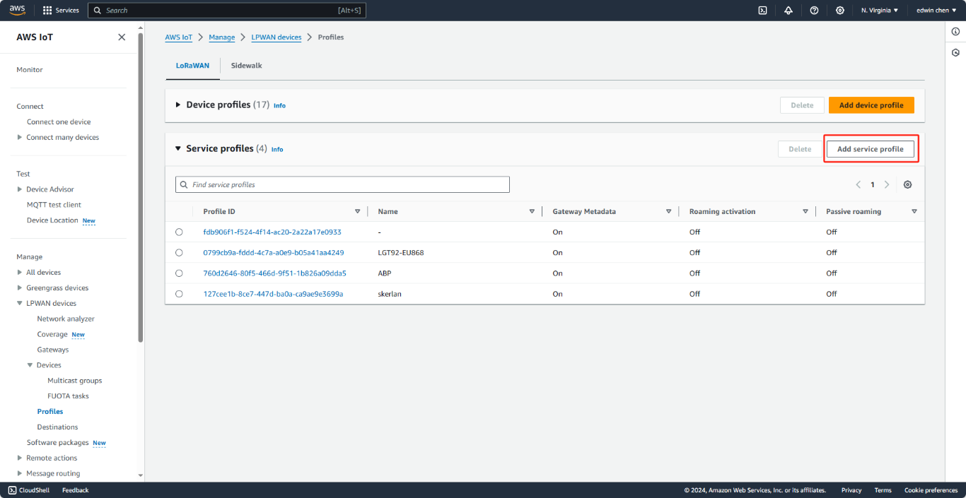
Add a service profile
Choose a service profile name (e.g. “Default service profile”)
Ensure that AddGWMetaData parameter is enabled. By enabling this parameter you will receive additional metadata with each device payload, for example RSSI and SNR for the data transmission.
This metadata could be used for network coverage optimization.
Finally, scroll down and click on “Add service profile”.
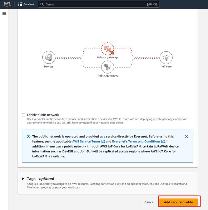
Add service profile2
3.2 Step 2 : Create an IAM roles for destinations
AWS IoT Core for LoRaWAN destinations require IAM roles that give AWS IoT Core for LoRaWAN the permissions necessary to send data to the AWS IoT rule. If such a role is not already defined, you'll need to define it so that it will appear in the list of roles.
To create an IAM policy for your AWS IoT Core for LoRaWAN destination role:
1. Open the Policies hub of the IAM console.
2. Choose Create policy, and choose the JSON tab.
3. In the editor, delete any content from the editor and paste this policy document.
{
"Version": "2012-10-17",
"Statement": [
{
"Effect": "Allow",
"Action": [
"iot:DescribeEndpoint",
"iot:Publish"
],
"Resource": "*"
}
]
}
4. Choose Review policy, and in Name, enter a name for this policy. You'll need this name to use in the next procedure. You can also describe this policy in Description, if you want.
5. Choose Create policy.
To create an IAM role for an AWS IoT Core for LoRaWAN destination:
1. Open the Roles hub of the IAM console and choose Create role.
2. In Select type of trusted entity, choose Another AWS account.
3. In Account ID, enter your AWS account ID, and then choose Next: Permissions.
4. In the search box, enter the name of the IAM policy that you created in the previous procedure.
5. In the search results, check the IAM policy that you created in the previous procedure.
6. Choose Next: Tags, and then choose Next: Review.
7. In Role name, enter the name of this role, and then choose Create role.
8. In the confirmation message, choose the name of the role you created to edit the new role.
9. In Summary, choose the Trust relationships tab, and then choose Edit trust relationship.
10. In Policy Document, change the Principal property to look like this example.
"Principal": {
"Service": "iotwireless.amazonaws.com"
},
After you change the Principal property, the complete policy document should look like this example.
{
"Version": "2012-10-17",
"Statement": [
{
"Effect": "Allow",
"Principal": {
"Service": "iotwireless.amazonaws.com"
},
"Action": "sts:AssumeRole",
"Condition": {}
}
]
}
11. To save your changes and exit, choose Update Trust Policy.
With this role defined, you can find it in the list of roles when you configure your AWS IoT Core for LoRaWAN destinations.
3.2.1 CREATE DESTINATION
Select Destinations view
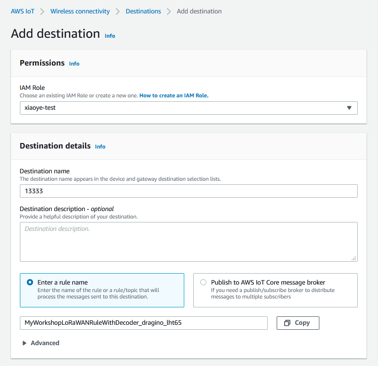
Please click on “Destinations” menu and afterwards please click on “Add destination”.
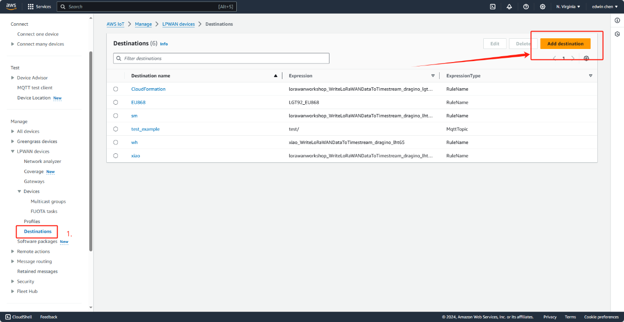
Select destinations
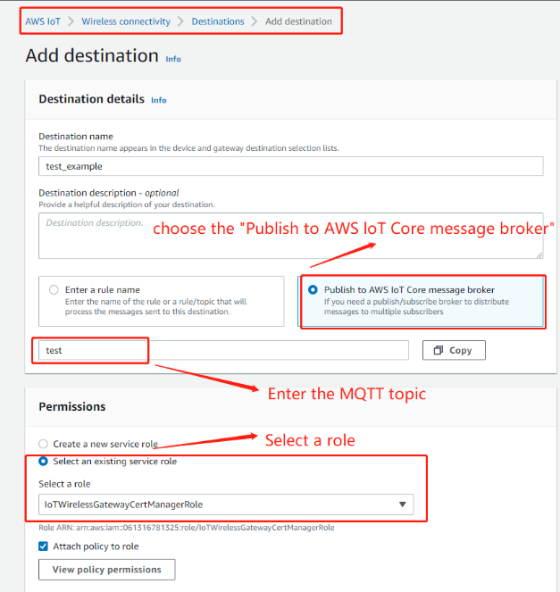
Provide input
Please provide the following input:
Please choose an IAM role that shall be used for the invocation of AWS IoT Rule.
Please select the destination name (e.g. “WorkshopDestination<Your name without spaces>”)
Please select the AWS IoT Rule name (e.g. “MyWorkshopLoRaWANRule<Your name without spaces>”)
click on “Add destination”
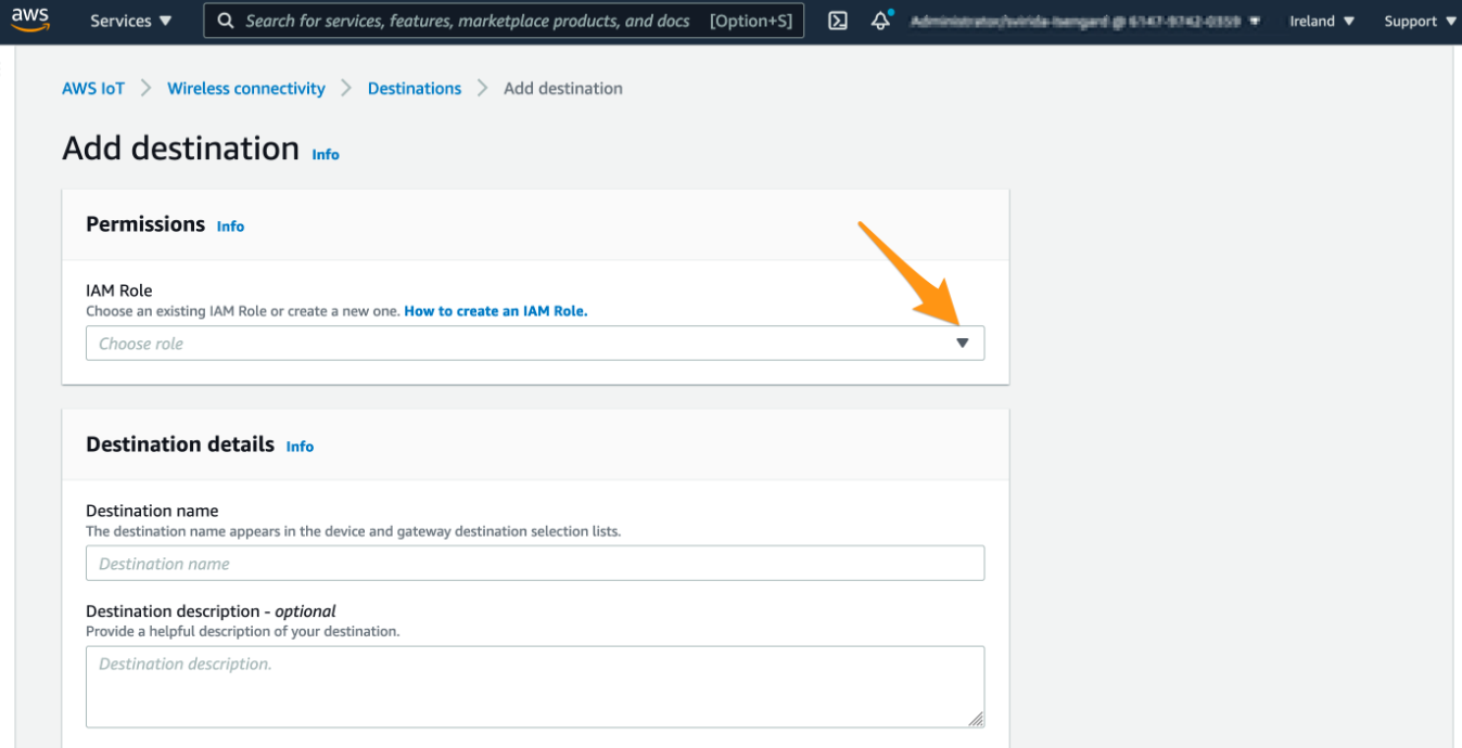
provide input
3.2.2 CREATE IOT RULE
Create Rule
user navigating to AWS IoT , Act, Rules and clicking on “Create” button.
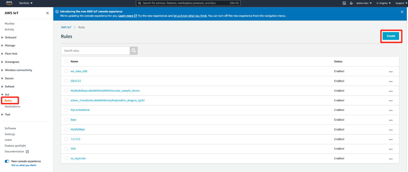
Rule create
Provide a rule name'
Please input the same IoT Rule name you used in a previous step when creating a new AWS IoT Core for the LoRaWAN destination (e.g. “test_example”).
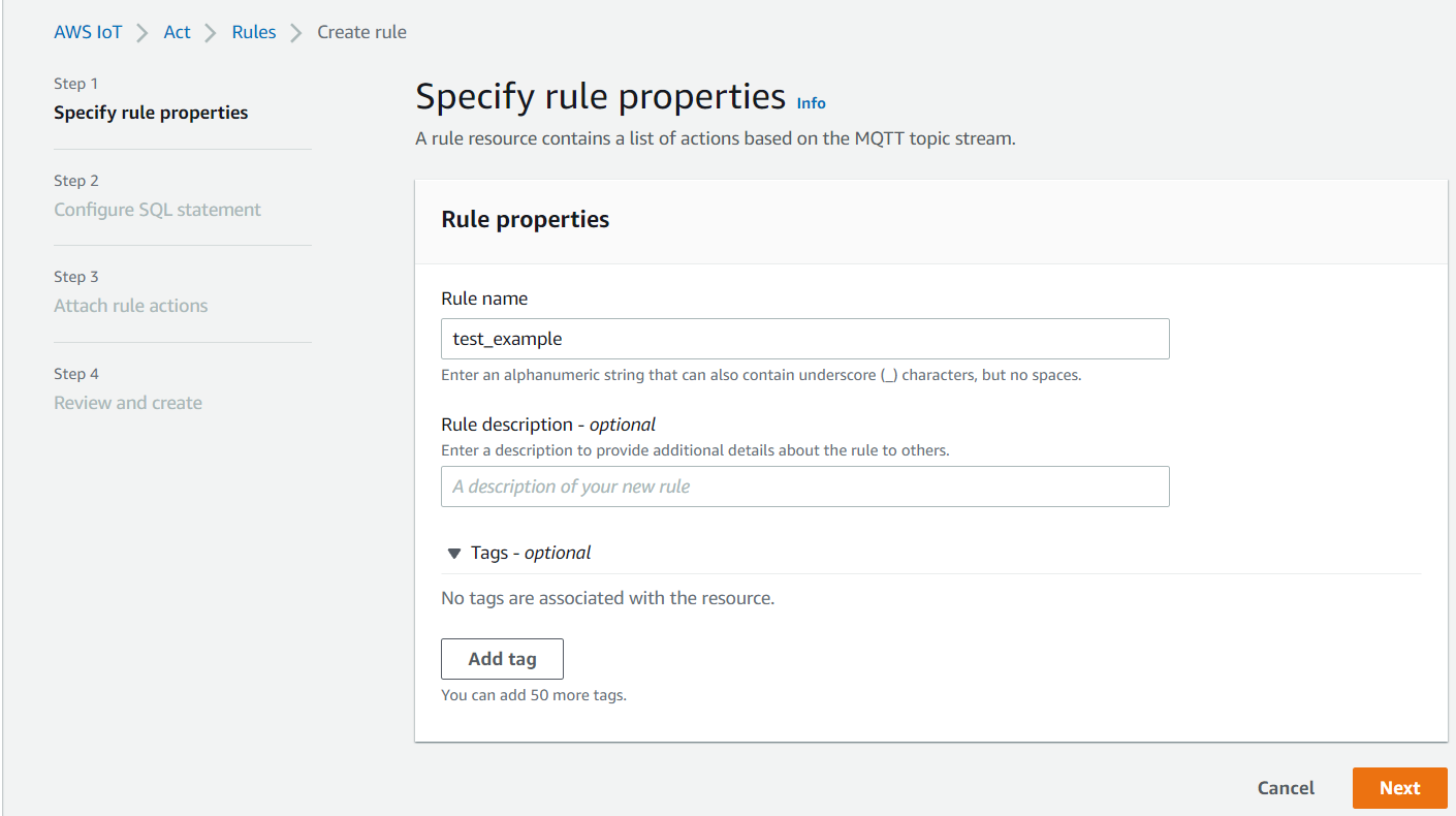
Enter Rule name
Provide IoT SQL query statement
Please put the following text into the rule query statement: SELECT *, timestamp() as timestamp
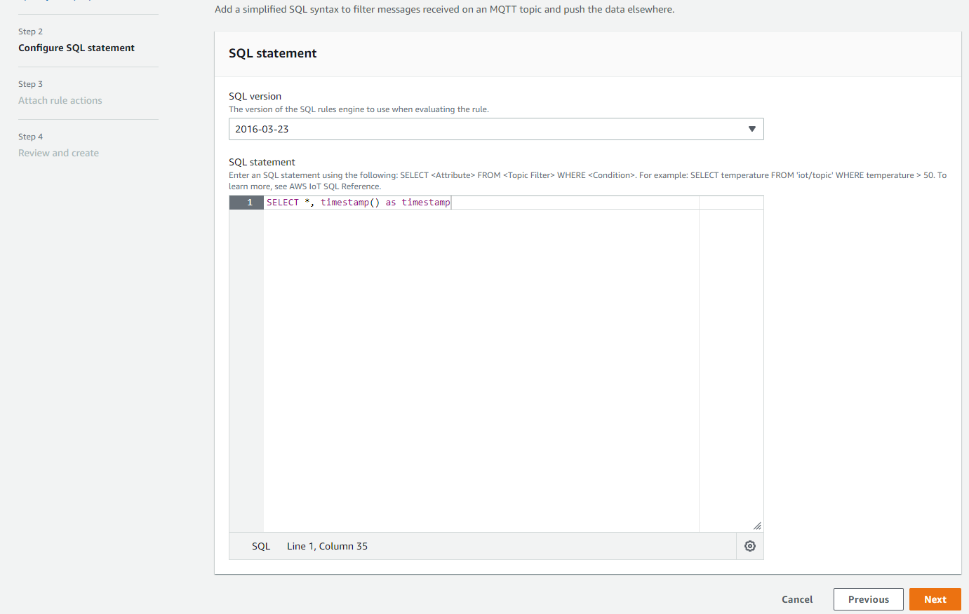
Enter SQL query statement
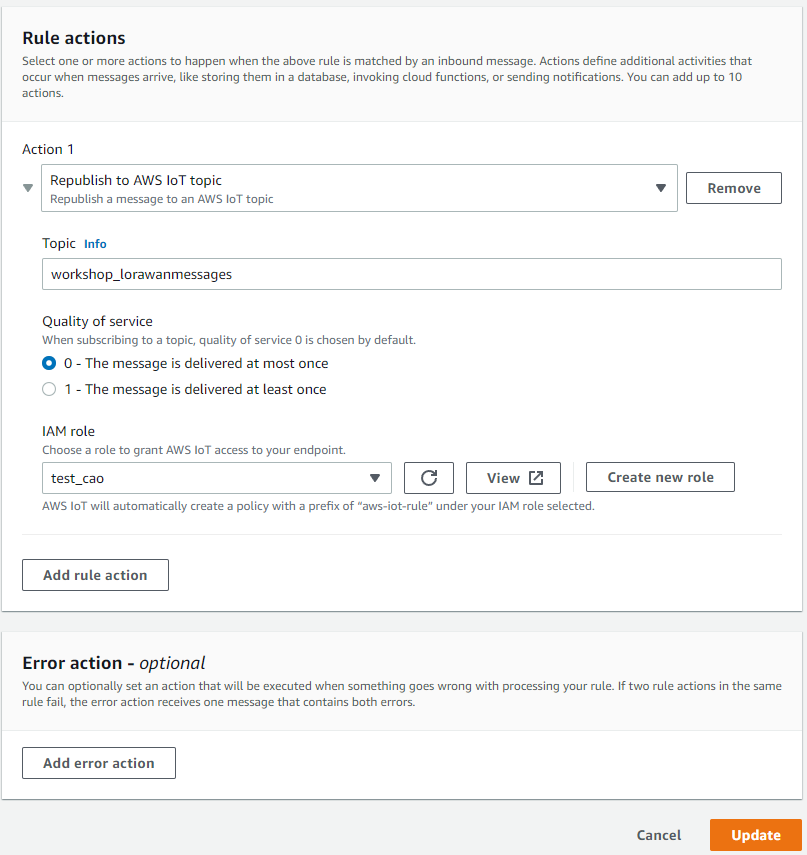
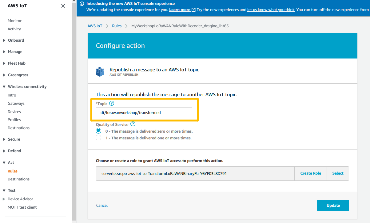
Select action “Republish to an AWS IoT Topic”
3.3 Step 3 : Create a destination for end node payloadDate
The PayloadDate of the node will be sent to this destination
a. In the destinatons,choose add destination.
b. In IMA Role, select the Role you created in the last step
c. In Destination name, give this destination a destination name.
d. In Rule name, give this rule a new name and remember it.
e. choose Add Destination.
Add destination
Note: The destination rule configuration sent by the end node payloadDate will be in the next step.
3.4 Step 4 : CREATE WIRELESS DEVICE
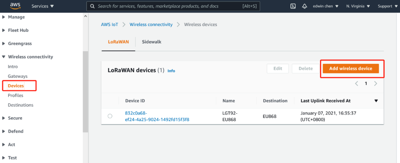
Users can register end nodes with AWS.
3.4.1 Open Add wireless device
a. In Device,choose Add wireless device.
b. In Wireless device specification,select OTTA 1.0.x
c. In OTTA 1.0.x
d. In Profiles,select profilees,and choose Next
Add device
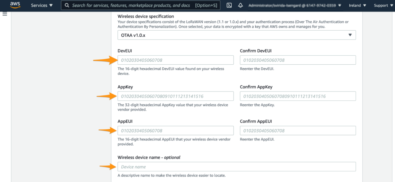
Enter device keys
Select device and service profile
Scroll down and endure that “Associate a thing with your wireless device” option is enabled. AWS will create a thing in AWS IoT for you and associate it with this device. Things in AWS IoT can make it easier to search for and manage your devices.
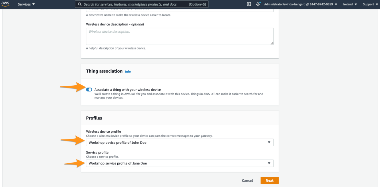
Seleck profile
3.4.2 Select a destination
Plese select a destination you have created in one of the previous steps and choose add device
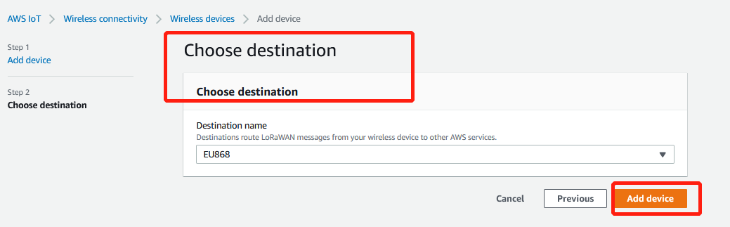
Add device_choose destition
REVIEW THE CREATED DEVICER
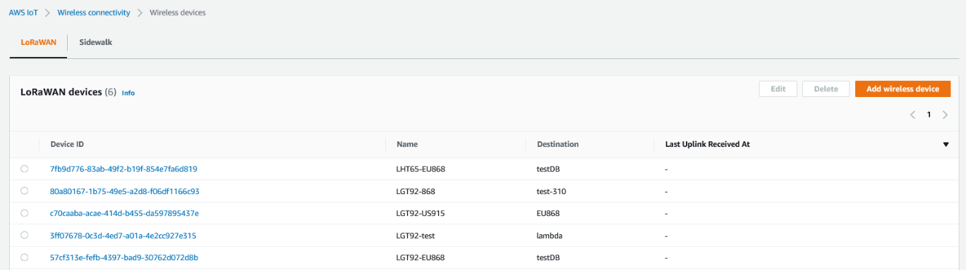
Uplink Received
VERIFY DEVICE CONNECTIVITY
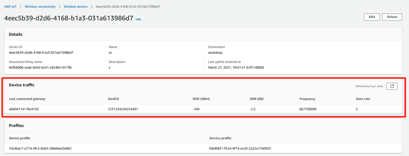
Verify device connectivity
3.4.3 Verify data ingestion
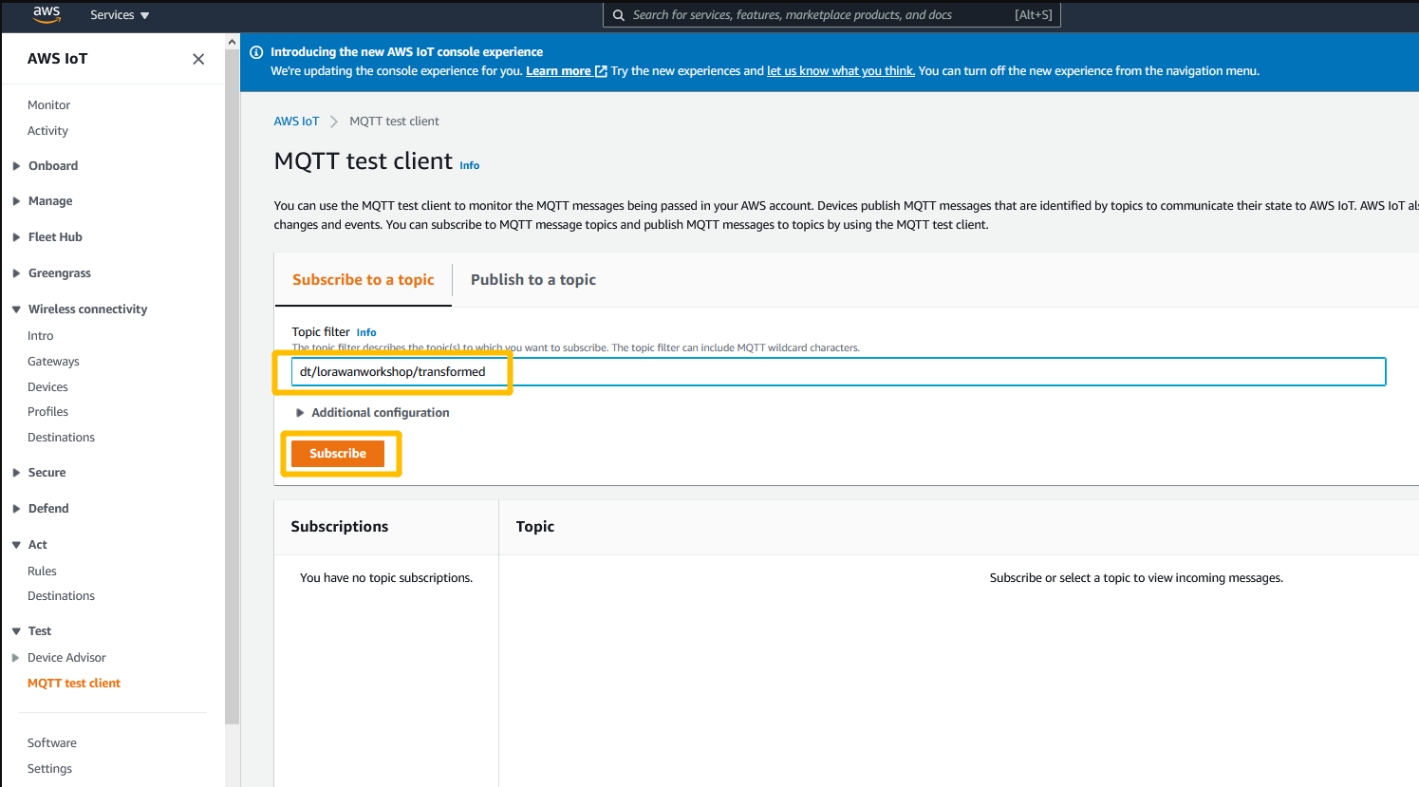
Open MQTT Test Client
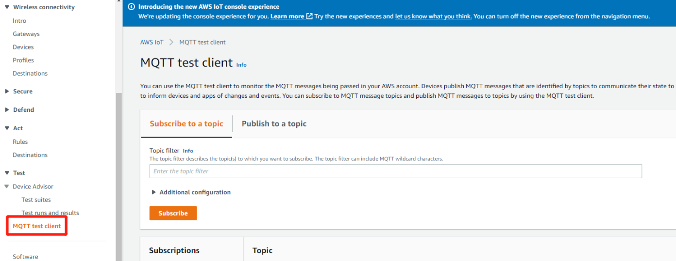
Open MQTT Client
Subscribe to topic
Please input the topic name workshop_lorawanmessages in “Subscription topic” field and click on “Subscribe to topic”.
Users can choose to subscribe to "#" ,"#" indicates to subscribe to all.
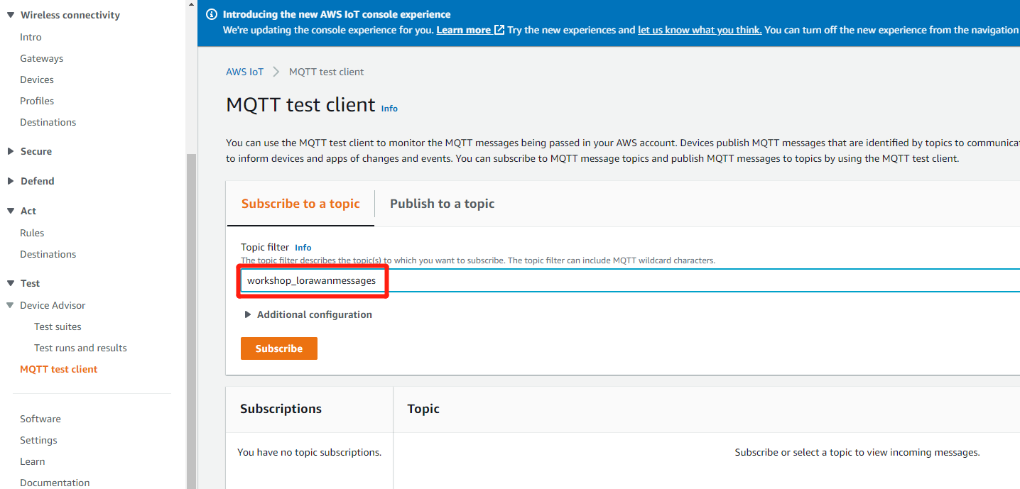
Subscription Topic
Trigger your device to send telemetry
User can start the registered device
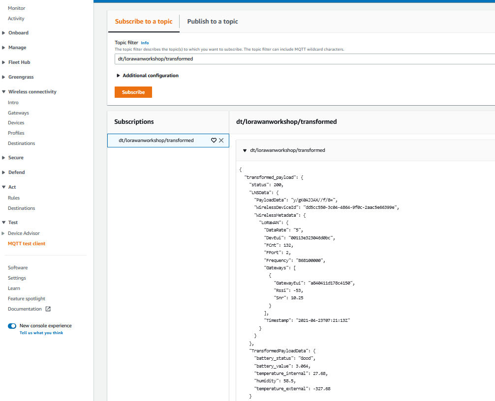
Review the incoming message from uesr's device
Please find below an explanation for some of the attributes:
PayloadData : Base64-encoded payload from the device
WirelessMetadata.FPort : FPort used by the device
WirelessMetadata.LoRaWAN.DevEui : EUI of the device sending the data
WirelessMetadata.LoRaWAN.Gateways : Information on RSSI and SNR per gateway
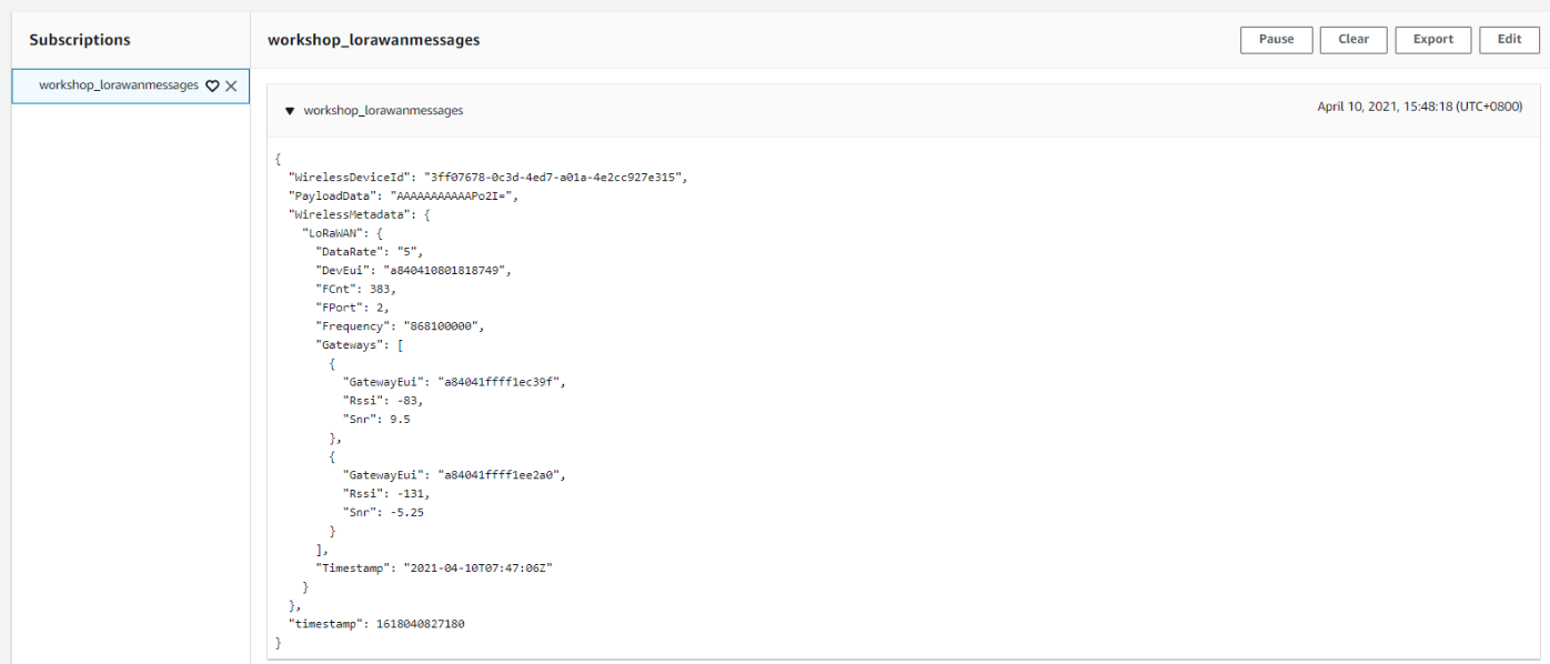
Review message
{
"WirelessDeviceId": "3ff07678-0c3d-4ed7-a01a-4e2cc927e315",
"PayloadData": "AAAAAAAAAAAPo2I=",
"WirelessMetadata": {
"LoRaWAN": {
"DataRate": "5",
"DevEui": "a840410801818749",
"FCnt": 579,
"FPort": 2,
"Frequency": "867500000",
"Gateways": [
{
"GatewayEui": "a84041ffff1ec39f",
"Rssi": -79,
"Snr": 7.25
},
{
"GatewayEui": "a84041ffff1ee2a0",
"Rssi": -129,
"Snr": -4
}
],
"Timestamp": "2021-04-10T08:16:06Z"
}
},
"timestamp": 1618042566345
}
How to decode Base64 data into hexadecimal representation
You can run the following command in your shell to decode Base64 payload data into their hexadecimal representation.
MacOS
$ echo -n "<Value of PayloadData>" | base64 -D | hexdump -v -e '/1 "%02x"'
Linux
$ echo -n "<Value of PayloadData>" | base64 -d | hexdump -v -e '/1 "%02x"'
Example
$ echo -n "7WkoOEfwfTTioxG6CatHBw==" | base64 -D | hexdump -v -e '/1 "%02x"'
ed69283847f07d34e2a311ba09ab4707
4. Format a notification by using an AWS Lambda function
4.1 Introduction
This tutorial demonstrates how to send MQTT message data to an AWS Lambda action for formatting and sending to another AWS service. In this tutorial, the AWS Lambda action uses the AWS SDK to send the formatted message to the Amazon SNS topic
4.1.1 What you'll learn in this tutorial
How to create and test an AWS Lambda function
How to use the AWS SDK in an AWS Lambda function to publish an Amazon SNS notification
How to use simple SQL queries and functions in a rule query statement
How to use the MQTT client to test an AWS IoT rule
4.1.2 In this tutorial, you'll:
Create an AWS Lambda function that sends a text message
Create an AWS IoT rule with an AWS Lambda rule action
Test the AWS IoT rule and AWS Lambda rule action
4.2 Approach A: DECODING BINARY PAYLOADS
4.2.1 Step 1 : Start deployment of a severless application with AWS Lambda function and AWS ioT Rule
1. Open AWS Lambda console by clicking on link
Users need to select the corresponding link according to the region they have selected ,For example: us-east-1 , eu-west-1
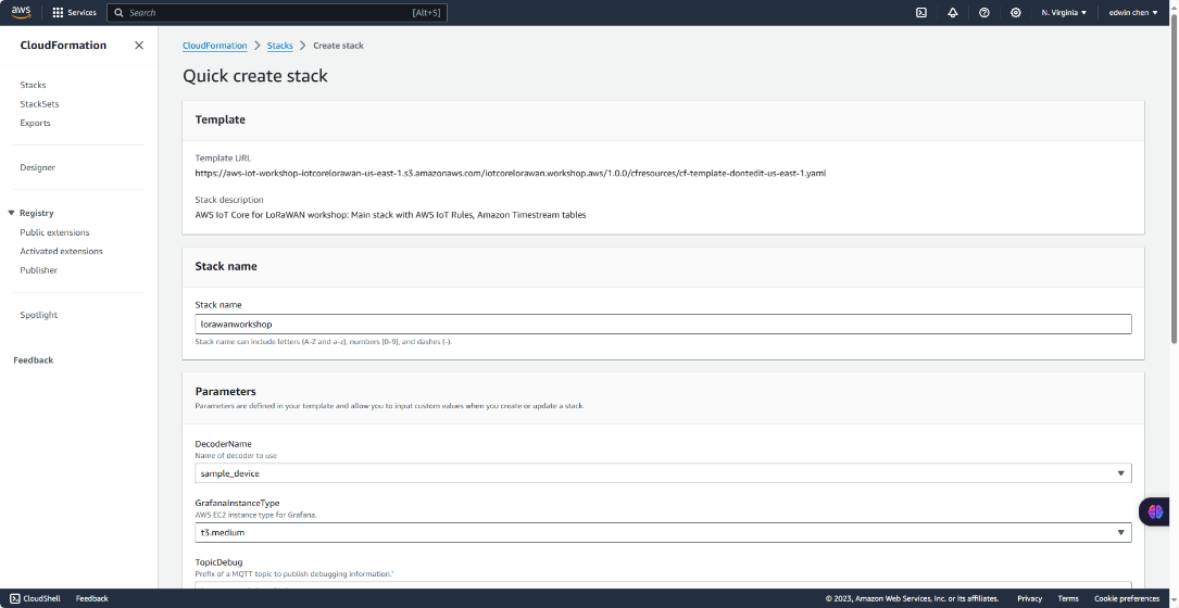
2. Select a decoder
Please scroll down to the bottom of the page. Please provide the parameter decoder name based on the following table.
Device Decoder name
LHT65 dragino_lht65
LBT1 dragino_lbt1
LSE01 dragino_lse01
LGT92 dragino_lgt92
LDS01 dragino_lds01
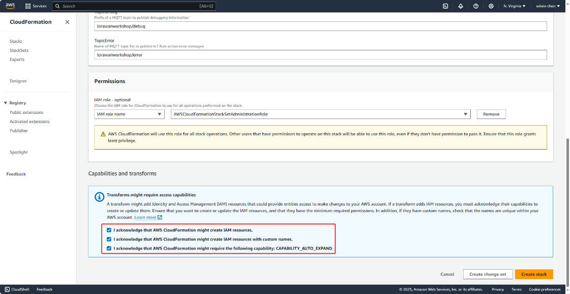
After that please check the box “I acknowledge that AWS CloudFormation might create IAM resources".
"I acknowledge that AWS CloudFormation might create IAM resources with custom names."
"I acknowledge that AWS CloudFormation might require the following capability: CAPABILITY_AUTO_EXPAND"
and click on "Create stack"
Seleck a decoder name
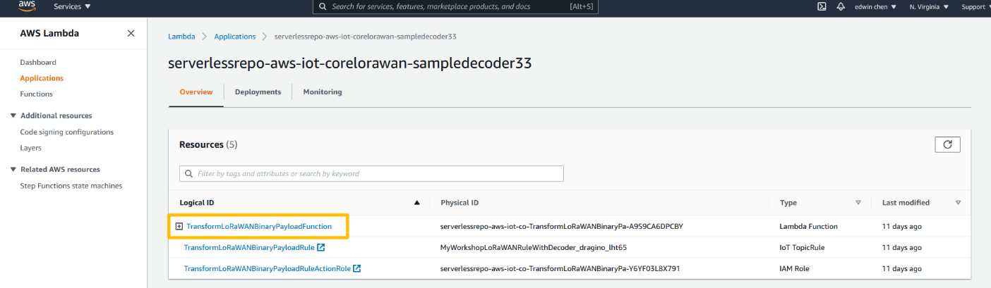
3. Review deployment
Please wait few seconds for a successful deployment. After that please click on the name of the Lambda function “TransformLoRaWANBinaryPayloadFunction”.
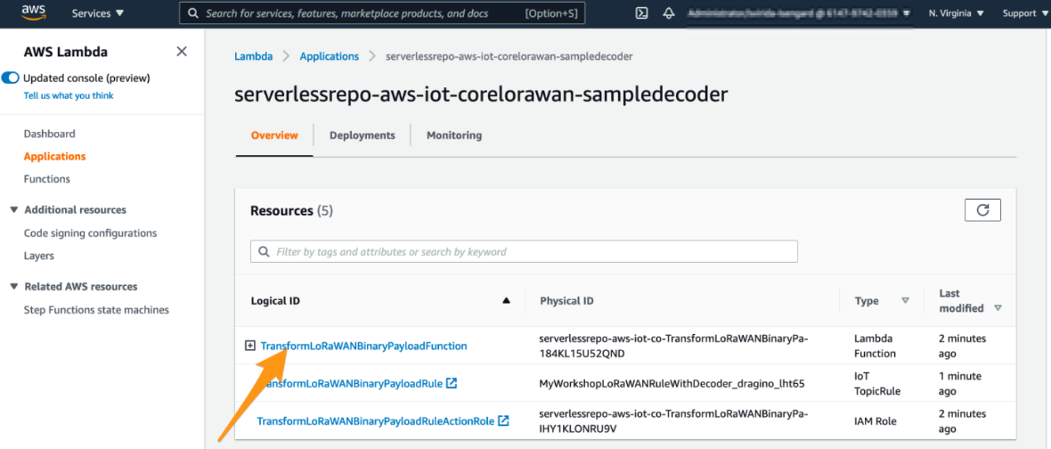
Review deployment
4. Create the test event
Please click on “Configure the test event”
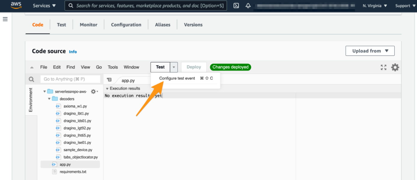
Create the test event
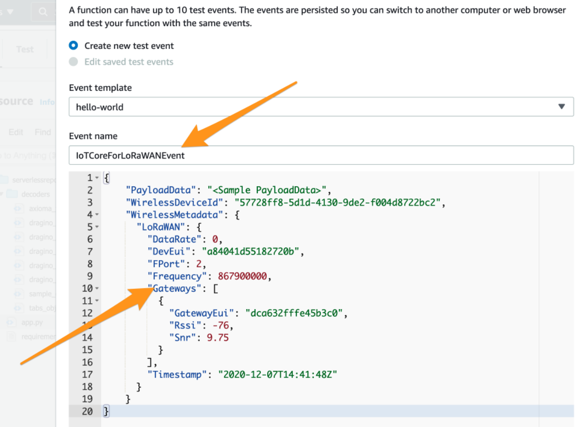
In the window that opens, please provide the event name e.g. IoTCoreForLoRaWANEvent. After that please paste the following JSON content:
{
"PayloadData": "<Sample PayloadData>",
"WirelessDeviceId": "57728ff8-5d1d-4130-9de2-f004d8722bc2",
"WirelessMetadata": {
"LoRaWAN": {
"DataRate": 0,
"DevEui": "a84041d55182720b",
"FPort": 2,
"Frequency": 867900000,
"Gateways": [
{
"GatewayEui": "dca632fffe45b3c0",
"Rssi": -76,
"Snr": 9.75
}
],
"Timestamp": "2020-12-07T14:41:48Z"
}
}
}
Create a new event
5. Provide PayloadData sample
Please replace the string <Sample PayloadData> in the JSON document with a sample payload for the device you selected in step 2 according to this table. After that please click on “Create”.
Device name Sample “PayloadData”
LHT65 -- y6QHxgG4AQhmf/8=
LSE01 -- AuHtlACmawQPVGM=
LGT92 -- DSEAAAEVCMUGpAA=
LBT1 -- DxwAAAIDQUJCQ0NEREVFRkYwMjcxMjFGNkFDMy0wNTk=
[[File:replace <Sample PayloadDate>.png|600px|none|thumb|replace <Sample PayloadDate>]]
6. Edit project Files
The project file needs to be modified when the user needs to test or add a new decoder, feel invited to switch to the “Code” section of the AWS Lambda function and inspect the Python source code. You will find the decoders for the individual devices in the directory decoders. The AWS Lambda function handler is in file app.py
Users can find the required decoder in this link, then added to the project.
How to modify see the figure below:
1) Add a decoder in app.py ---> For example, add code: import dragino_lht52
2) Add the decoder name to "VALID_PAYLOAD_DECODER_NAMES" ---> add dragino_lht52
3) Add the statement ---> DECODER_NAME = "dragino_lht52"
(The user can input the decoding project that needs to be tested)
4)Comment out "DECODER_NAME = os.environ.get("DECODER_NAME")"
(Comment out it in order to use other project files)
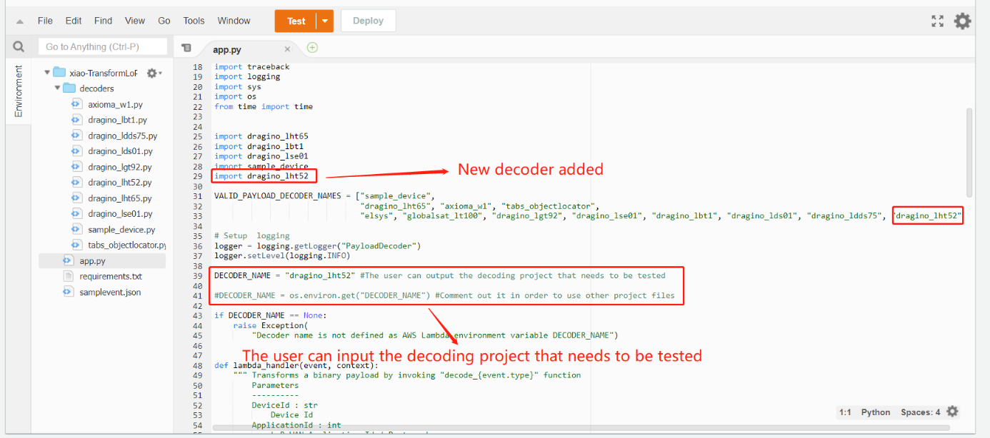
After the user finishes editing, Click on the "Deploy"
7. Run a test
Please click on “Test”.
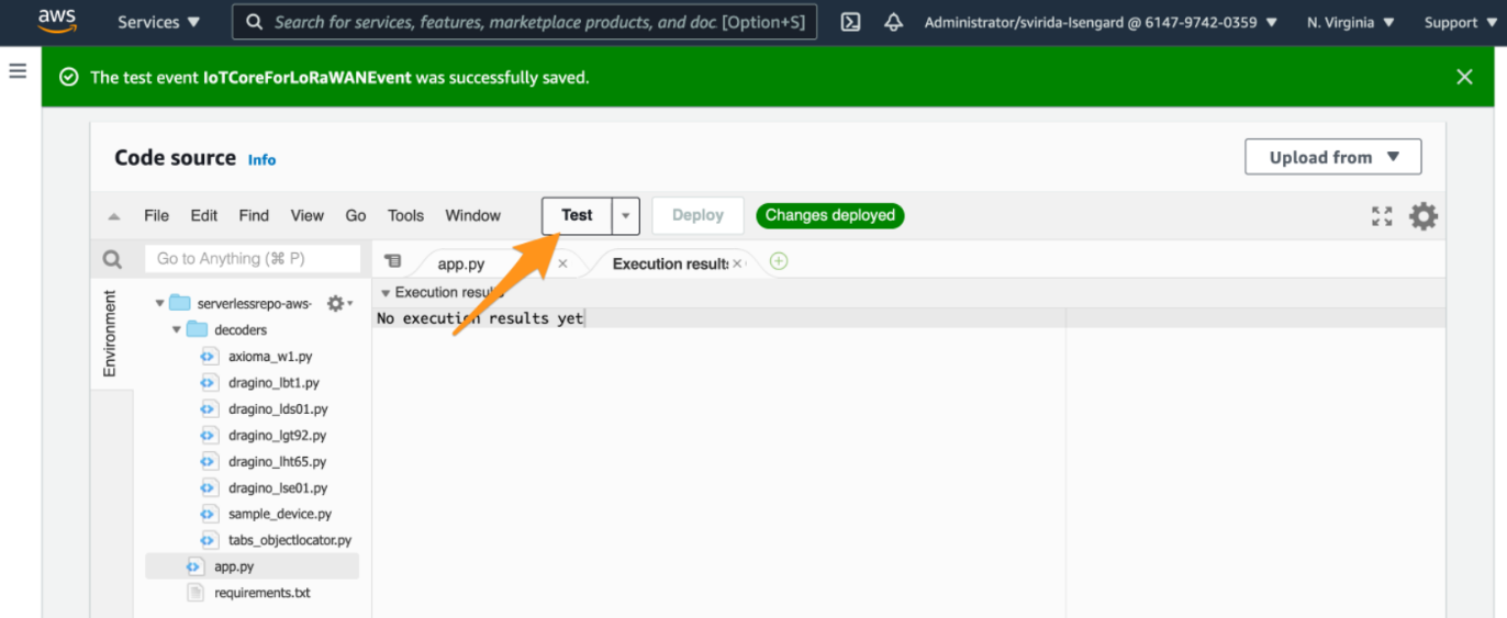
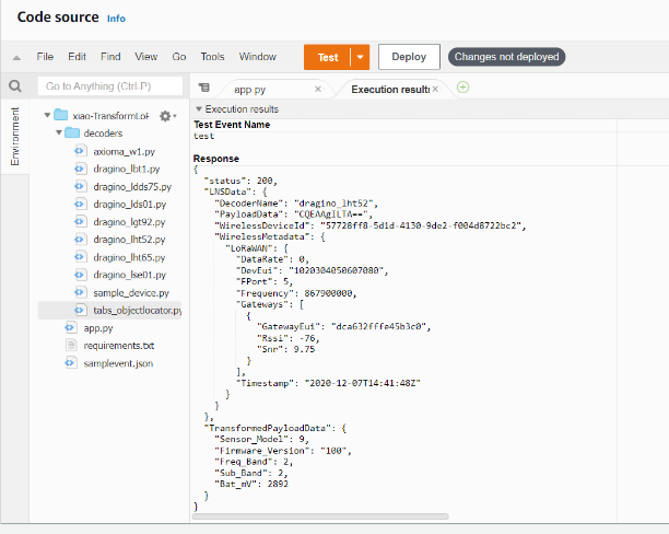
8. Check whether the decoding succeeds
The following example is the successful decoding of LHT52,
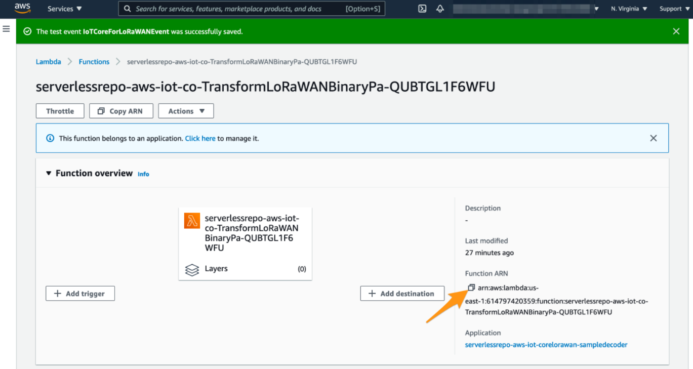
9. Note the AWS Lamdbda function ARN
As a preparation for the next step, please note the ARN of the deployed AWS Lambda function. We will need this ARN later to review the created AWS IoT Rule.
4.2.2 Step 2 : Update the Destination rule and get the device's payload
In this step, you update the IoT rule that forwards the device payload to your application. This rule is associated with the destination created earlier in Set up a Destination for device traffic.
1. Find the IoT Rule
2. Create a Destination with IoT Rule (MyWorkshopLoRaWANRuleWithDecoder_dragino_lht65)
3. Update the destination to the device
4. Check the payload
5. Approach A with MQTT
6. Approach B with Lambda
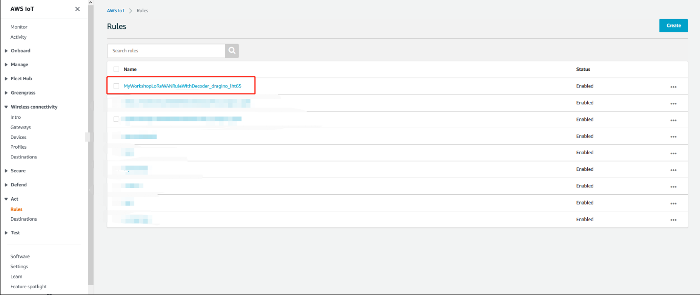
1. Find the IoT Rule MyWorkshopLoRaWANRuleWithDecoder_…
Please put the IoT Rule name prefix MyWorkshopLoRaWANRuleWithDecoder_ into the search field and click on the search symbol. The rule named MyWorkshopLoRaWANRuleWithDecoder_<Decoder name> should appear:
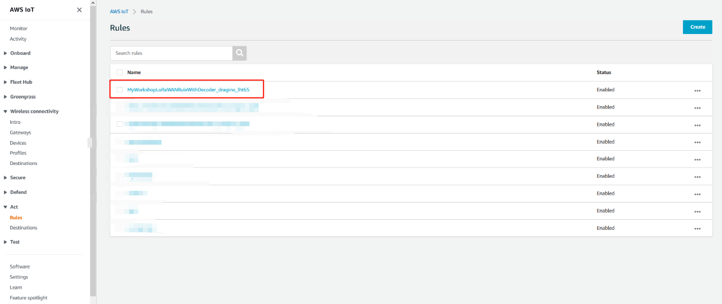
Find the IoT rule
2. Create a Destination with IoT Rule
(MyWorkshopLoRaWANRuleWithDecoder_dragino_lht65)
Create a Destnation
3. Update the destination to the device
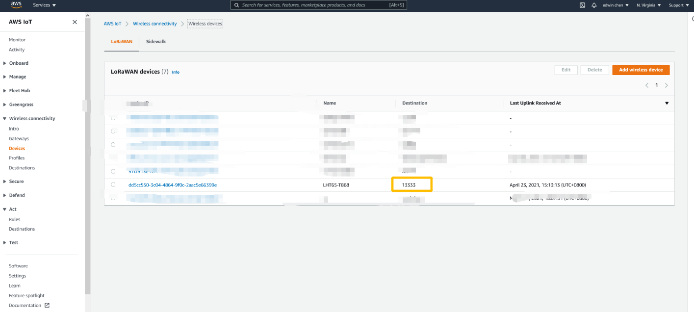
Update the destination to the device
4. Check the payload
Approach A with MQTT
click the rule
click the rule
Copy the Topic name
copy the rule name
Open MQTT client and subscrlibe Topic
Open MQTT client and subscrlibe Topic
Get the payload
Get the payload
Approach B with Lamdbda
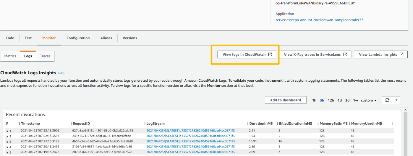
open lamdbda console and click the application
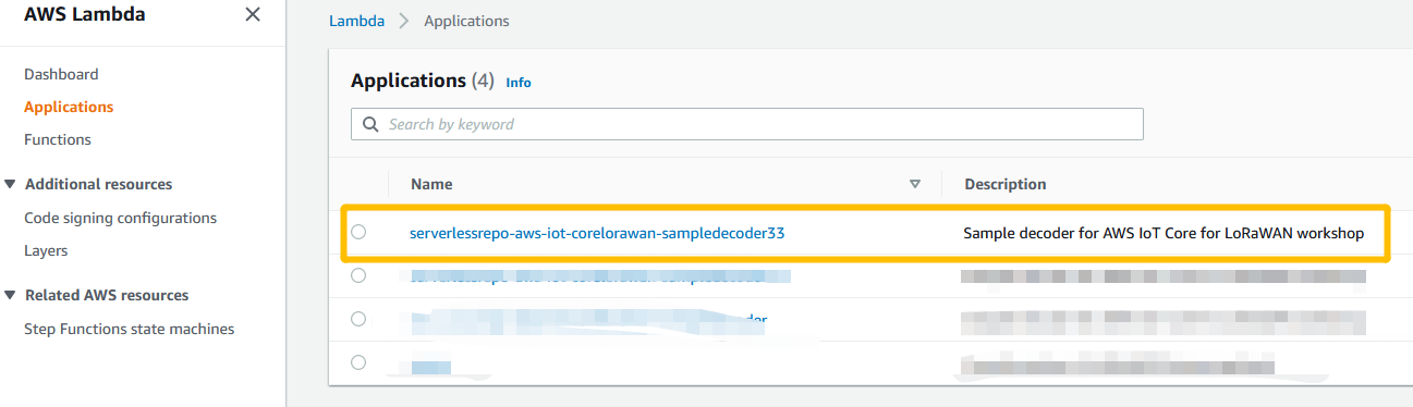
open lamdbda console and click the application
open lamdbda console and click the application
View logs in CloudWatch
View logs in CloudWatch
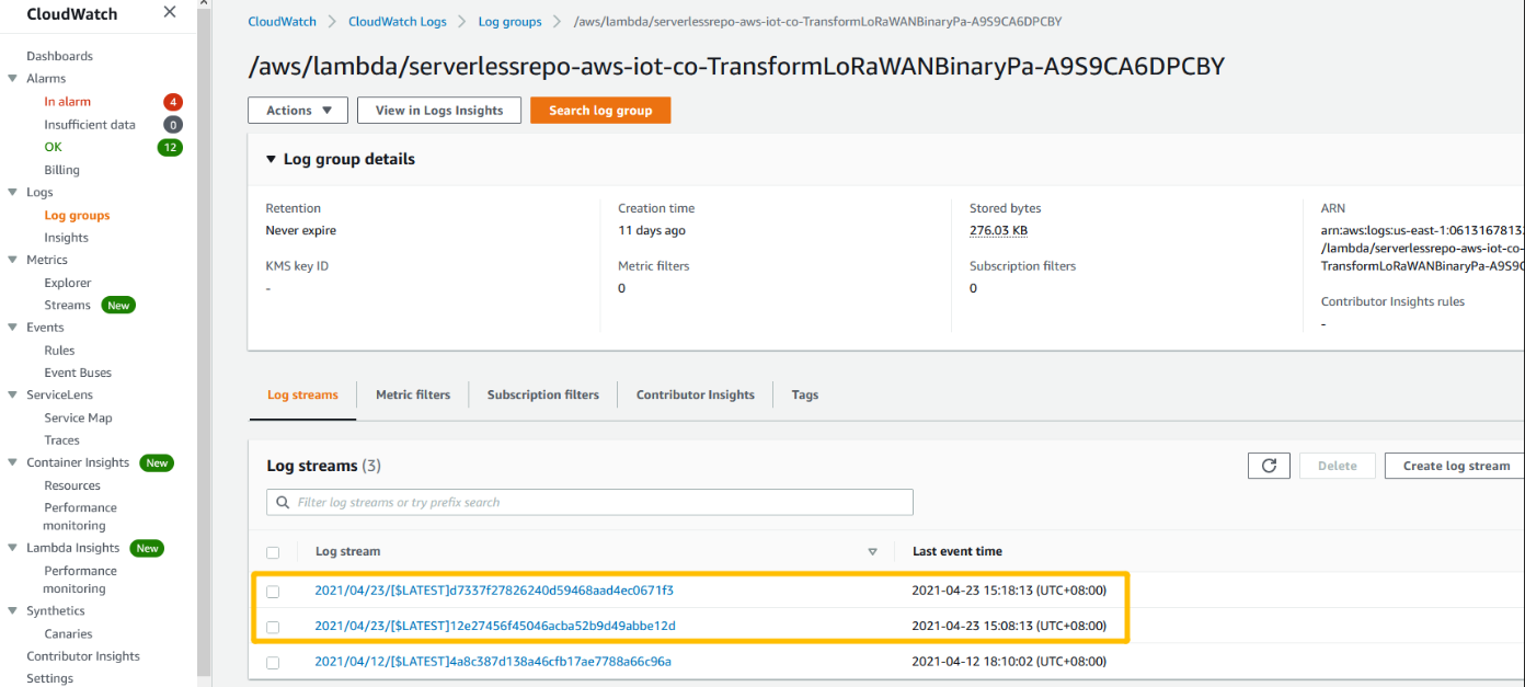
View logs in CloudWatch
4.3 Approach B Create an AWS Lambda function that sends a text message
The AWS Lambda function in this tutorial receives the result of the rule query statement, inserts the elements into a text string, and sends the resulting string to Amazon SNS as the message in a notification.
4.3.1 Step 1 : To create an AWS Lambda function that sends a text message
1. Create a new AWS Lambda function.
a. In the AWS Lambda console, choose Create function.
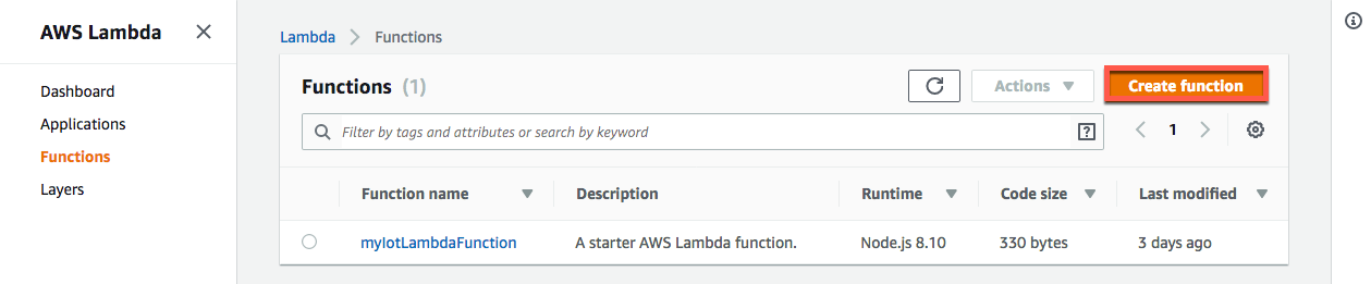
Create function
b. In Create function, select Use a blueprint. Search for and select the hello-world-python blueprint, and then choose Configure.
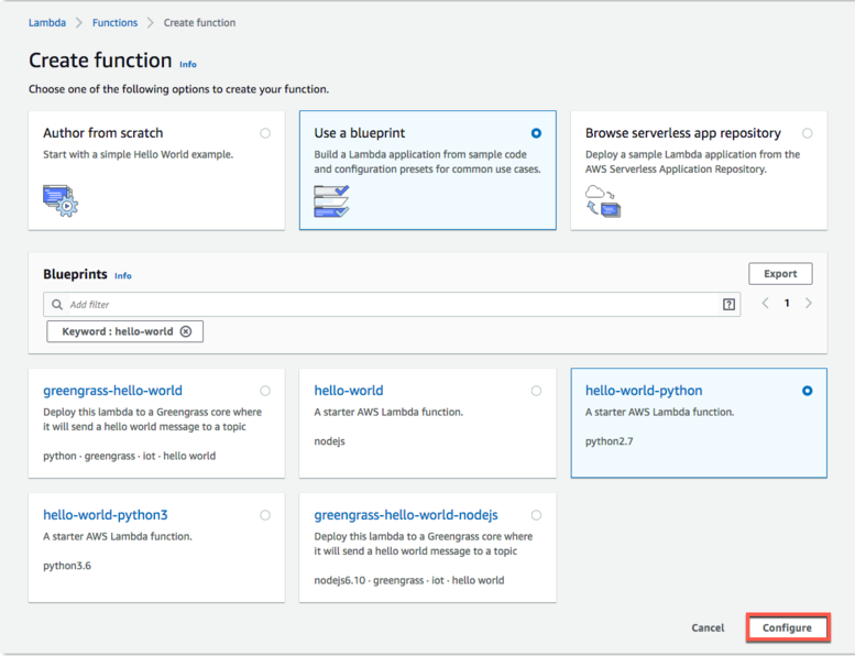
blueprint
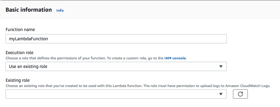
c. In Basic information:
1). In Function name, enter the name of this function, format-high-temp-notification.
2). In Execution role, choose Create a new role from AWS policy templates.
3). In Role name, enter the name of the new role, format-high-temp-notification-role.
4). In Policy templates - optional, search for and select Amazon SNS publish policy.
5). Choose Create function.
blueprint
2. Modify the blueprint code to format and send an Amazon SNS notification.
a. After you created your function, you should see the format-high-temp-notification details page. If you don't, open it from the Lambda Functions page.
b. In the format-high-temp-notification details page, choose the Configuration tab and scroll to the Function code panel.
c. In the Function code window, in the Environment pane, choose the Python file, lambda_function.py.
d. In the Function code window, delete all of the original program code from the blueprint and replace it with this code.
from __future__ import print_function
import json
import boto3
print('Loading function')
def lambda_handler(event, context):
# Parse the JSON message
eventText = json.dumps(event)
# Print the parsed JSON message to the console. You can view this text in the Monitoring tab in the AWS Lambda console or in the Amazon CloudWatch Logs console.
print('Received event: ', eventText)
# Create an SNS client
sns = boto3.client('sns')
# Publish a message to the specified topic
response = sns.publish (
TopicArn = 'arn:aws:iam::123456789012:My_IoT_SNS_Topic',
Message = eventText
)
print(response)
e. Choose Deploy.
Note: Replace the value of TopicArn with the ARN of the Amazon SNS topic that you created SNS topic in which SNS
Note: If you don't have SNS topic it does't affect the use of Lambda.About how to Create SNS topic will be show next chapter
3. In a new window, look up the Amazon Resource Name (ARN) of your Amazon SNS topic from the tutorial about how to Send an Amazon SNS notification.
a. In a new window, open the Topics page of the Amazon SNS console
b. In the Topics page, find the high_temp_notice notification topic in the list of Amazon SNS topics.
c. Find the ARN of the high_temp_notice notification topic to use in the next step.
4. Create a test case for your Lambda function.
a. In the Lambda Functionspage of the console,from Select a test eventto select Configure test events
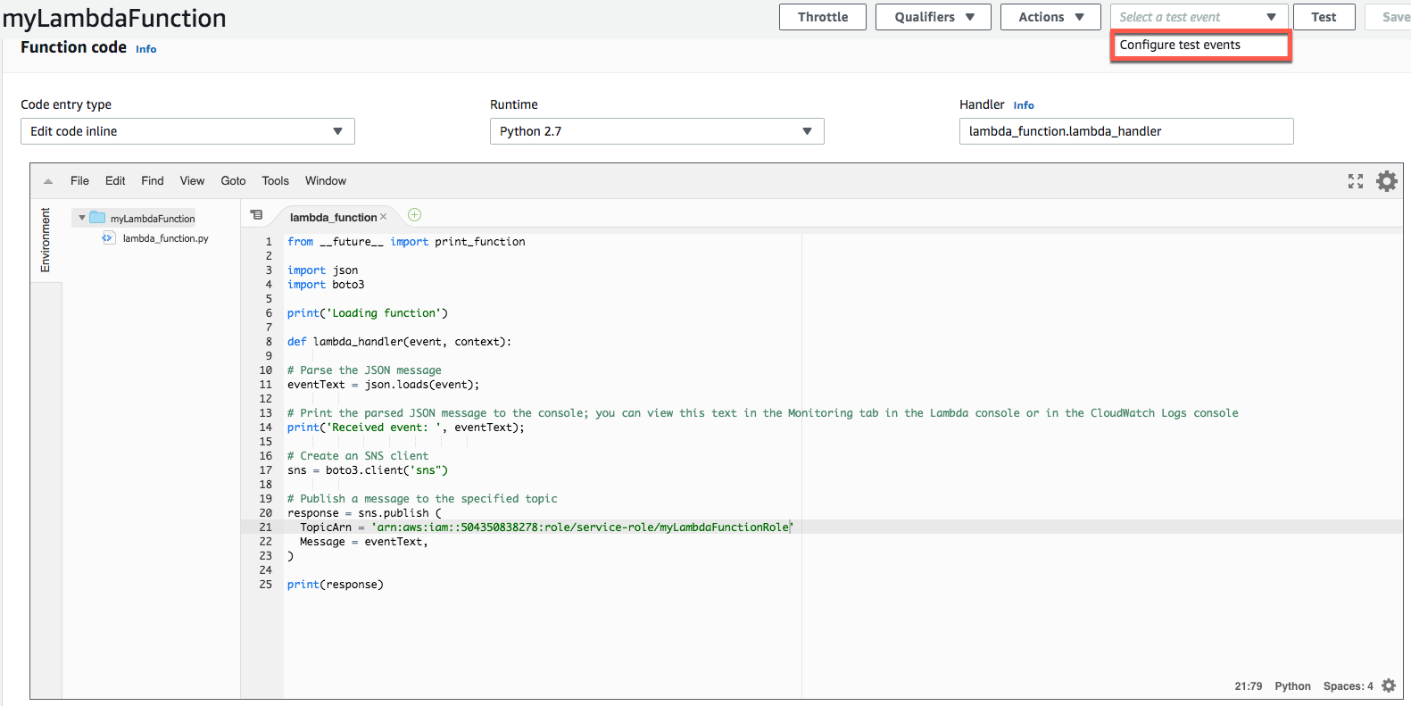
Configure test events
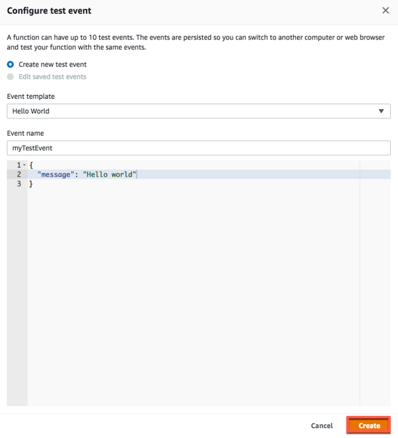
b. On Configure test event, enter a name for your test event and replace the message JSON with the following:
{
"message" : "Hello, world"
}
c. choose Create
event create
d. In the upper right of the Lambda function details page, choose Test to test your Lambda function with the message you specified in the test event.
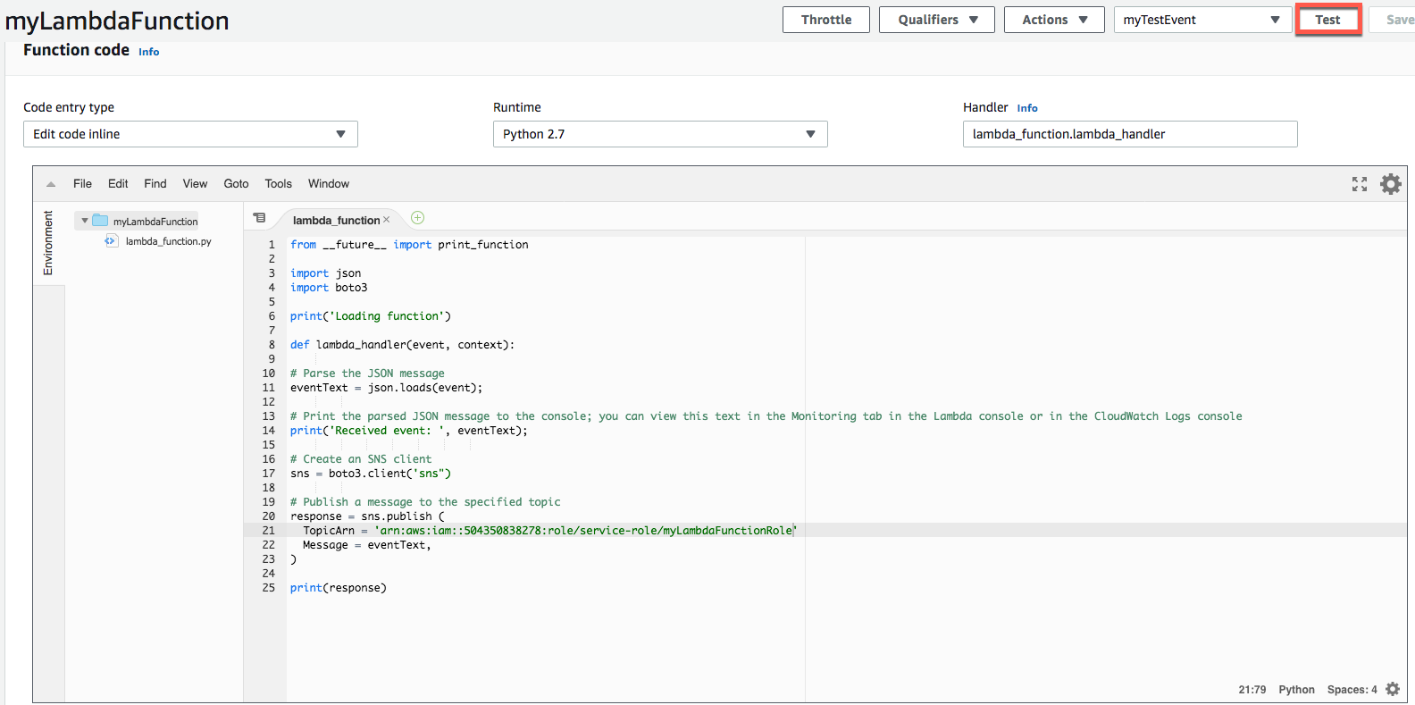
event test
e. Under your Lambda function code, on the Execution result tab, you see the output from the Lambda function.
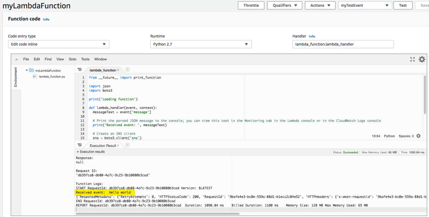
event output
Now The Lambda function table is created
4.3.2 Step 2 : Create Rule with Lambda function
1. Browse to the AWS IoT console, and in the navigation pane, select Act
File: Console Act.png
2. Choose Create to create an AWS IoT rule.
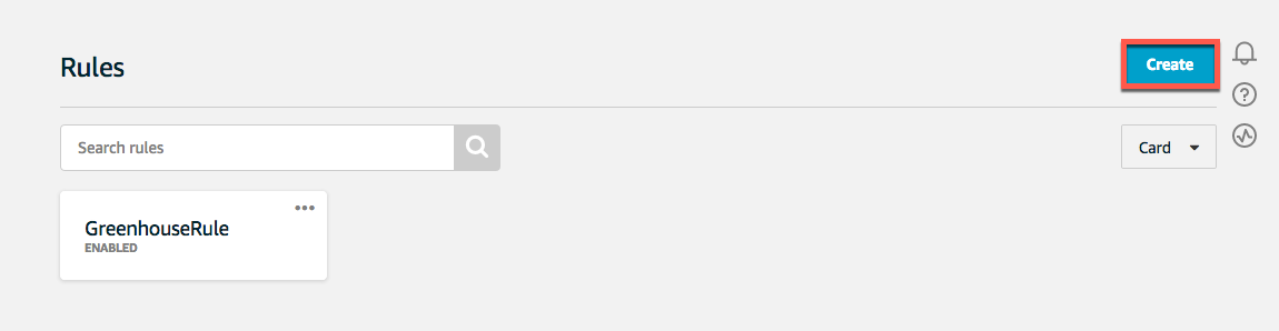
create Rule
3. On the Create a rule page, enter a name for your rule.
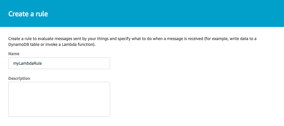
enter a Rule name
4. In Rule query statement, enter the following query:
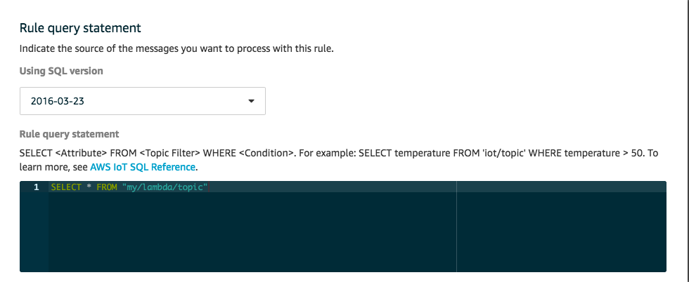
enter the following query
5. In Set one or more actions, select Add action.

Add action
6. Under the select operation, select Send a Message to a Lambda Function and then select the configuration operation.
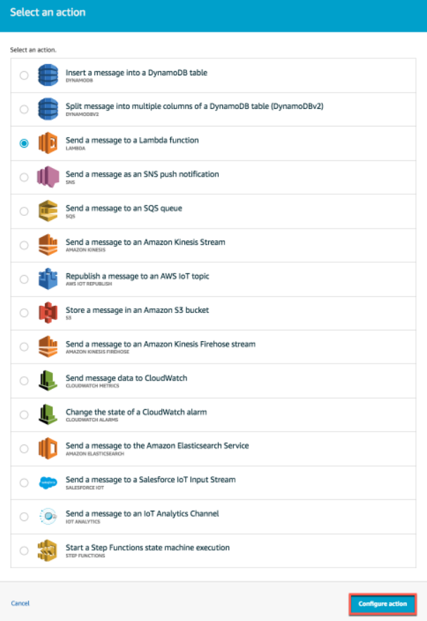
select operation
5. For End Node
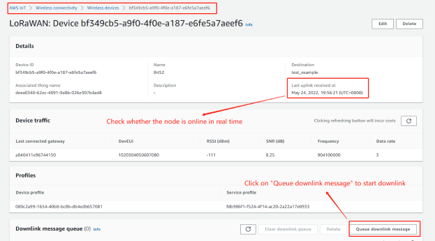
5.1 AWS Downlink Note
Prerequisites: The node must be online in real-time before downlink.
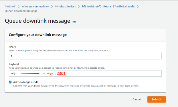
Convert the data to Base64
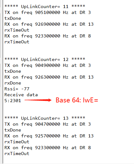
When the serial port logs of downlink are received, the Receive date is displayed
In addition to the above methods, there is also a downlink,This method requires a certain amount of manipulation,
Users can view this Downlink method 2
5.2 Node decoder
6. Trouble Shooting
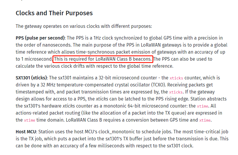
6.1 Time sync& Time drift
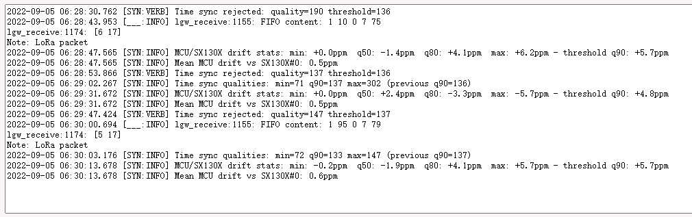
Time Sync
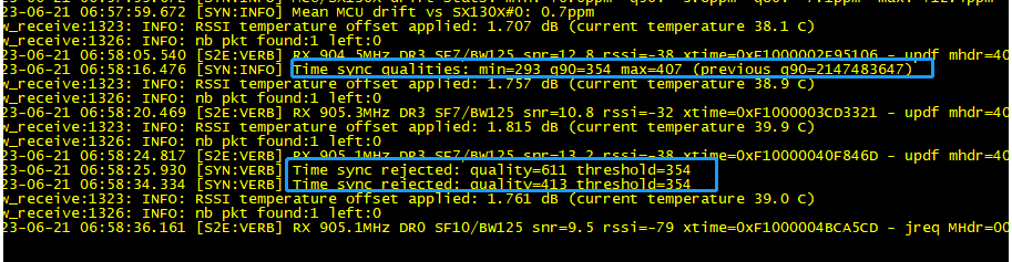
This is the normal log output of the station because the log level is Debug so the time sync info will be output as the debug.
For example, the station keeps statistics on the time sync quality and discards measurements whose quality is considered an outlier:
Time sync rejected: quality=413 threshold=354 and Time sync qualities: min=293 q90=354 max=407 (previous q90=2147483647)
Time drift
Time drift is for the Class B device. so if your device is not class B and can transfer the data to AWS normally, you can ignore it