
Contents:
- 1. Introduction
- 2. Configure LSE01 to connect to LoRaWAN network
- 3. Using the AT Commands
- 4. FAQ
- 5. Trouble Shooting
- 6. Order Info
- 7. Packing Info
- 8. Support
1. Introduction
1.1 What is LoRaWAN Soil Moisture & EC Sensor
The Dragino LSE01 is a LoRaWAN Soil Moisture & EC Sensor for IoT of Agriculture. It is designed to measure the soil moisture of saline-alkali soil and loamy soil. The soil sensor uses FDR method to calculate the soil moisture with the compensation from soil temperature and conductivity. It also has been calibrated in factory for Mineral soil type.
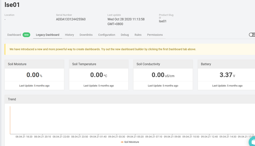
It detects Soil Moisture, Soil Temperature and Soil Conductivity, and uploads the value via wireless to LoRaWAN IoT Server.
The LoRa wireless technology used in LES01 allows device to send data and reach extremely long ranges at low data-rates. It provides ultra-long range spread spectrum communication and high interference immunity whilst minimizing current consumption.
LES01 is powered by 4000mA or 8500mAh Li-SOCI2 battery, It is designed for long term use up to 10 years.
Each LES01 is pre-load with a set of unique keys for LoRaWAN registrations, register these keys to local LoRaWAN server and it will auto connect after power on.


1.2 Features
- LoRaWAN 1.0.3 Class A
- Ultra low power consumption
- Monitor Soil Moisture
- Monitor Soil Temperature
- Monitor Soil Conductivity
- Bands: CN470/EU433/KR920/US915/EU868/AS923/AU915/IN865
- AT Commands to change parameters
- Uplink on periodically
- Downlink to change configure
- IP66 Waterproof Enclosure
- 4000mAh or 8500mAh Battery for long term use
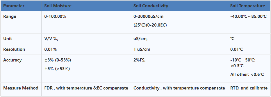
1.3 Specification
Measure Volume: Base on the centra pin of the probe, a cylinder with 7cm diameter and 10cm height.
1.4 Applications
- Smart Agriculture
1.5 Firmware Change log
LSE01 v1.0 : Release
2. Configure LSE01 to connect to LoRaWAN network
2.1 How it works
The LSE01 is configured as LoRaWAN OTAA Class A mode by default. It has OTAA keys to join LoRaWAN network. To connect a local LoRaWAN network, you need to input the OTAA keys in the LoRaWAN IoT server and power on the LSE0150. It will automatically join the network via OTAA and start to send the sensor value
In case you can’t set the OTAA keys in the LoRaWAN OTAA server, and you have to use the keys from the server, you can use AT Commands .
2.2 Quick guide to connect to LoRaWAN server (OTAA)
Following is an example for how to join the TTN v3 LoRaWAN Network. Below is the network structure; we use the LG308 as a LoRaWAN gateway in this example.

The LG308 is already set to connected to TTN network , so what we need to now is configure the TTN server.
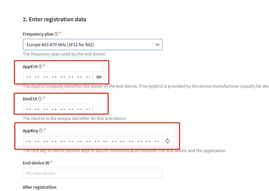
Step 1: Create a device in TTN with the OTAA keys from LSE01.
Each LSE01 is shipped with a sticker with the default device EUI as below:

You can enter this key in the LoRaWAN Server portal. Below is TTN screen shot:
Add APP EUI in the application

Add APP KEY and DEV EUI
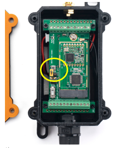
Step 2: Power on LSE01
Put a Jumper on JP2 to power on the device. ( The Jumper must be in FLASH position).
Step 3: The LSE01 will auto join to the TTN network. After join success, it will start to upload messages to TTN and you can see the messages in the panel.

2.3 Uplink Payload
2.3.1 MOD=0(Default Mode)
LSE01 will uplink payload via LoRaWAN with below payload format:
Uplink payload includes in total 11 bytes.
Size (bytes) | 2 | 2 | 2 | 2 | 2 | 1 | ||||||
|---|---|---|---|---|---|---|---|---|---|---|---|---|
| Value | BAT | Temperature (Reserve, Ignore now) |Soil Moisture|Soil Temperature|Soil Conductivity (EC)| MOD & Digital Interrupt (Optional)
2.3.2 MOD=1(Original value)This mode can get the original AD value of moisture and original conductivity (with temperature drift compensation).
2.3.3 Battery InfoCheck the battery voltage for LSE01. Ex1: 0x0B45 = 2885mV Ex2: 0x0B49 = 2889mV 2.3.4 Soil MoistureGet the moisture content of the soil. The value range of the register is 0-10000(Decimal), divide this value by 100 to get the percentage of moisture in the soil. For example, if the data you get from the register is 0x05 0xDC, the moisture content in the soil is 05DC(H) = 1500(D) /100 = 15%. 2.3.5 Soil TemperatureGet the temperature in the soil. The value range of the register is -4000 - +800(Decimal), divide this value by 100 to get the temperature in the soil. For example, if the data you get from the register is 0x09 0xEC, the temperature content in the soil is Example: If payload is 0105H: ((0x0105 & 0x8000)>>15 === 0),temp = 0105(H)/100 = 2.61 °C If payload is FF7EH: ((FF7E & 0x8000)>>15 ===1),temp = (FF7E(H)-FFFF(H))/100 = -1.29 °C 2.3.6 Soil Conductivity (EC)Obtain soluble salt concentration in soil or soluble ion concentration in liquid fertilizer or planting medium. The value range of the register is 0 - 20000(Decimal)( Can be greater than 20000). For example, if the data you get from the register is 0x00 0xC8, the soil conductivity is 00C8(H) = 200(D) = 200 uS/cm. Generally, the EC value of irrigation water is less than 800uS / cm.
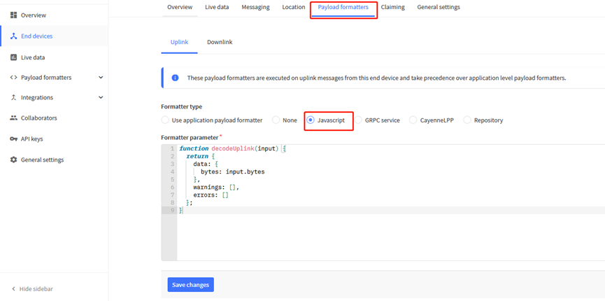
2.3.7 MODFirmware version at least v2.1 supports changing mode. For example, bytes[10]=90 mod=(bytes[10]>>7)&0x01=1. Downlink Command: If payload = 0x0A00, workmode=0 If payload = 0x0A01, workmode=1 2.3.8 Decode payload in The Things NetworkWhile using TTN network, you can add the payload format to decode the payload.
The payload decoder function for TTN is here: LSE01 TTN Payload Decoder: http://www.dragino.com/downloads/index.php?dir=LoRa_End_Node/LSE01/Payload_Decoder/ 2.4 Uplink IntervalThe LSE01 by default uplink the sensor data every 20 minutes. User can change this interval by AT Command or LoRaWAN Downlink Command. See this link: Change Uplink Interval 2.5 Downlink PayloadBy default, LSE50 prints the downlink payload to console port.
Examples:
If the payload=0100003C, it means set the END Node’s TDC to 0x00003C=60(S), while type code is 01. Payload: 01 00 00 1E TDC=30S Payload: 01 00 00 3C TDC=60S
If payload = 0x04FF, it will reset the LSE01
Downlink Payload: 05000001, Set AT+CFM=1 or 05000000 , set AT+CFM=0 2.6 Show Data in DataCake IoT ServerDATACAKE provides a human friendly interface to show the sensor data, once we have data in TTN, we can use DATACAKE to connect to TTN and see the data in DATACAKE. Below are the steps: Step 1: Be sure that your device is programmed and properly connected to the network at this time. Step 2: To configure the Application to forward data to DATACAKE you will need to add integration. To add the DATACAKE integration, perform the following steps:
Step 3: Create an account or log in Datacake. Step 4: Search the LSE01 and add DevEUI.
After added, the sensor data arrive TTN, it will also arrive and show in Mydevices.
2.7 Frequency PlansThe LSE01 uses OTAA mode and below frequency plans by default. If user want to use it with different frequency plan, please refer the AT command sets. 2.7.1 EU863-870 (EU868)Uplink: 868.1 - SF7BW125 to SF12BW125 868.3 - SF7BW125 to SF12BW125 and SF7BW250 868.5 - SF7BW125 to SF12BW125 867.1 - SF7BW125 to SF12BW125 867.3 - SF7BW125 to SF12BW125 867.5 - SF7BW125 to SF12BW125 867.7 - SF7BW125 to SF12BW125 867.9 - SF7BW125 to SF12BW125 868.8 - FSK Downlink: Uplink channels 1-9 (RX1) 869.525 - SF9BW125 (RX2 downlink only) 2.7.2 US902-928(US915)Used in USA, Canada and South America. Default use CHE=2 Uplink: 903.9 - SF7BW125 to SF10BW125 904.1 - SF7BW125 to SF10BW125 904.3 - SF7BW125 to SF10BW125 904.5 - SF7BW125 to SF10BW125 904.7 - SF7BW125 to SF10BW125 904.9 - SF7BW125 to SF10BW125 905.1 - SF7BW125 to SF10BW125 905.3 - SF7BW125 to SF10BW125 Downlink: 923.3 - SF7BW500 to SF12BW500 923.9 - SF7BW500 to SF12BW500 924.5 - SF7BW500 to SF12BW500 925.1 - SF7BW500 to SF12BW500 925.7 - SF7BW500 to SF12BW500 926.3 - SF7BW500 to SF12BW500 926.9 - SF7BW500 to SF12BW500 927.5 - SF7BW500 to SF12BW500 923.3 - SF12BW500(RX2 downlink only) 2.7.3 CN470-510 (CN470)Used in China, Default use CHE=1 Uplink: 486.3 - SF7BW125 to SF12BW125 486.5 - SF7BW125 to SF12BW125 486.7 - SF7BW125 to SF12BW125 486.9 - SF7BW125 to SF12BW125 487.1 - SF7BW125 to SF12BW125 487.3 - SF7BW125 to SF12BW125 487.5 - SF7BW125 to SF12BW125 487.7 - SF7BW125 to SF12BW125 Downlink: 506.7 - SF7BW125 to SF12BW125 506.9 - SF7BW125 to SF12BW125 507.1 - SF7BW125 to SF12BW125 507.3 - SF7BW125 to SF12BW125 507.5 - SF7BW125 to SF12BW125 507.7 - SF7BW125 to SF12BW125 507.9 - SF7BW125 to SF12BW125 508.1 - SF7BW125 to SF12BW125 505.3 - SF12BW125 (RX2 downlink only) 2.7.4 AU915-928(AU915)Default use CHE=2 Uplink: 916.8 - SF7BW125 to SF12BW125 917.0 - SF7BW125 to SF12BW125 917.2 - SF7BW125 to SF12BW125 917.4 - SF7BW125 to SF12BW125 917.6 - SF7BW125 to SF12BW125 917.8 - SF7BW125 to SF12BW125 918.0 - SF7BW125 to SF12BW125 918.2 - SF7BW125 to SF12BW125 Downlink: 923.3 - SF7BW500 to SF12BW500 923.9 - SF7BW500 to SF12BW500 924.5 - SF7BW500 to SF12BW500 925.1 - SF7BW500 to SF12BW500 925.7 - SF7BW500 to SF12BW500 926.3 - SF7BW500 to SF12BW500 926.9 - SF7BW500 to SF12BW500 927.5 - SF7BW500 to SF12BW500 923.3 - SF12BW500(RX2 downlink only) 2.7.5 AS920-923 & AS923-925 (AS923)Default Uplink channel: 923.2 - SF7BW125 to SF10BW125 923.4 - SF7BW125 to SF10BW125 Additional Uplink Channel: (OTAA mode, channel added by JoinAccept message) AS920~AS923 for Japan, Malaysia, Singapore: 922.2 - SF7BW125 to SF10BW125 922.4 - SF7BW125 to SF10BW125 922.6 - SF7BW125 to SF10BW125 922.8 - SF7BW125 to SF10BW125 923.0 - SF7BW125 to SF10BW125 922.0 - SF7BW125 to SF10BW125 AS923 ~ AS925 for Brunei, Cambodia, Hong Kong, Indonesia, Laos, Taiwan, Thailand, Vietnam: 923.6 - SF7BW125 to SF10BW125 923.8 - SF7BW125 to SF10BW125 924.0 - SF7BW125 to SF10BW125 924.2 - SF7BW125 to SF10BW125 924.4 - SF7BW125 to SF10BW125 924.6 - SF7BW125 to SF10BW125 Downlink: Uplink channels 1-8 (RX1) 923.2 - SF10BW125 (RX2) 2.7.6 KR920-923 (KR920)Default channel: 922.1 - SF7BW125 to SF12BW125 922.3 - SF7BW125 to SF12BW125 922.5 - SF7BW125 to SF12BW125 Uplink: (OTAA mode, channel added by JoinAccept message) 922.1 - SF7BW125 to SF12BW125 922.3 - SF7BW125 to SF12BW125 922.5 - SF7BW125 to SF12BW125 922.7 - SF7BW125 to SF12BW125 922.9 - SF7BW125 to SF12BW125 923.1 - SF7BW125 to SF12BW125 923.3 - SF7BW125 to SF12BW125 Downlink: Uplink channels 1-7(RX1) 921.9 - SF12BW125 (RX2 downlink only; SF12BW125 might be changed to SF9BW125) 2.7.7 IN865-867 (IN865)Uplink: 865.0625 - SF7BW125 to SF12BW125 865.4025 - SF7BW125 to SF12BW125 865.9850 - SF7BW125 to SF12BW125 Downlink: Uplink channels 1-3 (RX1) 866.550 - SF10BW125 (RX2) 2.8 LED IndicatorThe LSE01 has an internal LED which is to show the status of different state.
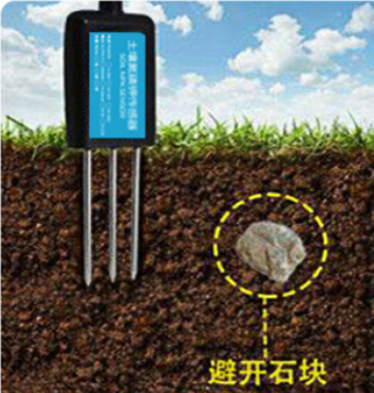
2.9 Installation in SoilMeasurement the soil surface
Choose the proper measuring position. Avoid the probe to touch rocks or hard things. Split the surface soil according to the measured deep. Keep the measured as original density. Vertical insert the probe into the soil to be measured. Make sure not shake when inserting.
Dig a hole with diameter > 20CM. Horizontal insert the probe to the soil and fill the hole for long term measurement. 2.10 Firmware Change LogFirmware download link:
Firmware Upgrade Method: Firmware Upgrade Instruction
V1.0. Release 2.11 Battery Analysis2.11.1 Battery TypeThe LSE01 battery is a combination of a 4000mAh Li/SOCI2 Battery and a Super Capacitor. The battery is non-rechargeable battery type with a low discharge rate (<2% per year). This type of battery is commonly used in IoT devices such as water meter. The battery is designed to last for more than 5 years for the LSN50. The battery-related documents are as below: 2.11.2 Battery NoteThe Li-SICO battery is designed for small current / long period application. It is not good to use a high current, short period transmit method. The recommended minimum period for use of this battery is 5 minutes. If you use a shorter period time to transmit LoRa, then the battery life may be decreased. 2.11.3 Replace the batteryIf Battery is lower than 2.7v, user should replace the battery of LSE01. You can change the battery in the LSE01.The type of battery is not limited as long as the output is between 3v to 3.6v. On the main board, there is a diode (D1) between the battery and the main circuit. If you need to use a battery with less than 3.3v, please remove the D1 and shortcut the two pads of it so there won’t be voltage drop between battery and main board. The default battery pack of LSE01 includes a ER18505 plus super capacitor. If user can’t find this pack locally, they can find ER18505 or equivalence, which will also work in most case. The SPC can enlarge the battery life for high frequency use (update period below 5 minutes) 3. Using the AT Commands3.1 Access AT CommandsLSE01 supports AT Command set in the stock firmware. You can use a USB to TTL adapter to connect to LSE01 for using AT command, as below.
Or if you have below board, use below connection:
In the PC, you need to set the serial baud rate to 9600 to access the serial console for LSE01. LSE01 will output system info once power on as below: Below are the available commands, a more detailed AT Command manual can be found at AT Command Manual: http://www.dragino.com/downloads/index.php?dir=LoRa_End_Node/LSE01/ AT+<CMD>=?AT+<CMD>? : Help on <CMD> AT+<CMD>=?AT+<CMD> : Run <CMD> AT+<CMD>=?AT+<CMD>=<value> : Set the value AT+<CMD>=?AT+<CMD>=? : Get the value General Commands AT : Attention AT? : Short Help ATZ : MCU Reset AT+TDC : Application Data Transmission Interval Keys, IDs and EUIs management AT+APPEUI : Application EUI AT+APPKEY : Application Key AT+APPSKEY : Application Session Key AT+DADDR : Device Address AT+DEUI : Device EUI AT+NWKID : Network ID (You can enter this command change only after successful network connection) AT+NWKSKEY : Network Session Key Joining and sending date on LoRa network AT+CFM : Confirm Mode AT+CFS : Confirm Status AT+JOIN : Join LoRa? Network AT+NJM : LoRa? Network Join Mode AT+NJS : LoRa? Network Join Status AT+RECV : Print Last Received Data in Raw Format AT+RECVB : Print Last Received Data in Binary Format AT+SEND : Send Text Data AT+SENB : Send Hexadecimal Data LoRa Network Management AT+ADR : Adaptive Rate AT+CLASS : LoRa Class(Currently only support class A AT+DCS : Duty Cycle Setting AT+DR : Data Rate (Can Only be Modified after ADR=0) AT+FCD : Frame Counter Downlink AT+FCU : Frame Counter Uplink AT+JN1DL : Join Accept Delay1 AT+JN2DL : Join Accept Delay2 AT+PNM : Public Network Mode AT+RX1DL : Receive Delay1 AT+RX2DL : Receive Delay2 AT+RX2DR : Rx2 Window Data Rate AT+RX2FQ : Rx2 Window Frequency AT+TXP : Transmit Power AT+ MOD : Set work mode Information AT+RSSI : RSSI of the Last Received Packet AT+SNR : SNR of the Last Received Packet AT+VER : Image Version and Frequency Band AT+FDR : Factory Data Reset AT+PORT : Application Port AT+CHS : Get or Set Frequency (Unit: Hz) for Single Channel Mode AT+CHE : Get or Set eight channels mode, Only for US915, AU915, CN470 4. FAQ4.1 How to change the LoRa Frequency Bands/Region?You can follow the instructions for how to upgrade image.
How to set up LSE01 to work in 8 channel mode By default, the frequency bands US915, AU915, CN470 work in 72 frequencies. Many gateways are 8 channel gateways, and in this case, the OTAA join time and uplink schedule is long and unpredictable while the end node is hopping in 72 frequencies.
You can configure the end node to work in 8 channel mode by using the AT+CHE command. The 500kHz channels are always included for OTAA.
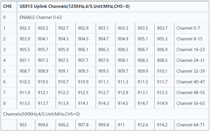
For example, in US915 band, the frequency table is as below. By default, the end node will use all channels (0~71) for OTAA Join process. After the OTAA Join, the end node will use these all channels (0~71) to send uplink packets.
When you use the TTN network, the US915 frequency bands use are:
Because the end node is now hopping in 72 frequency, it makes it difficult for the devices to Join the TTN network and uplink data. To solve this issue, you can access the device via the AT commands and run: to set the end node to work in 8 channel mode. The device will work in Channel 8-15 & 64-71 for OTAA, and channel 8-15 for Uplink.
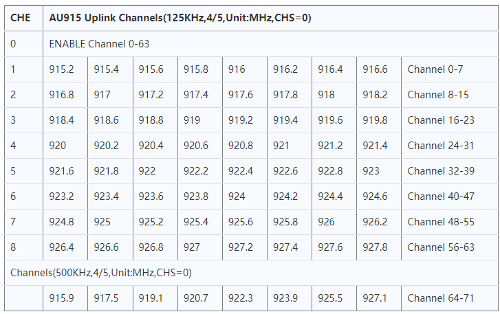
The AU915 band is similar. Below are the AU915 Uplink Channels.
5. Trouble Shooting5.1 Why I can’t join TTN in US915 / AU915 bands?It is due to channel mapping. Please see the Eight Channel Mode section above for details. 5.2 AT Command input doesn’t workIn the case if user can see the console output but can’t type input to the device. Please check if you already include the ENTER while sending out the command. Some serial tool doesn’t send ENTER while press the send key, user need to add ENTER in their string. 5.3 Device rejoin in at the second uplink packetIssue describe as below:
Cause for this issue: The fuse on LSE01 is not large enough, some of the soil probe require large current up to 5v 800mA, in a short pulse. When this happen, it cause the device reboot so user see rejoin. Solution: All new shipped LSE01 after 2020-May-30 will have this to fix. For the customer who see this issue, please bypass the fuse as below:
6. Order InfoPart Number: LSE01-XX-YY XX: The default frequency band
YY: Battery Option
7. Packing Info
Package Includes:
Dimension and weight:
8. Support
|


