LDS02 - LoRaWAN Door Sensor User Manual

Table of Contents:
- 1. Introduction
- 2. Power ON LDS02
- 3. How to Install LDS02
- 4. Operation Mode
- 5. Battery & How to replace
- 6. Use AT Commands
- 7. FAQ
- 7.1 How to upgrade the image?
- 7.2 How to change the LoRa Frequency Bands/Region?
- 7.3 Can I disable uplinks for each event to save battery life?
- 7.4 How can I change the Subband for LDS02?
- 7.5 My sensor worked for Helium AU915 before, but now it doesn't work. Why?
- 7.6 Why do I see different working temperatures for the device?
- 7.7 The device keeps rejoining the network and is not working properly
- 8. Ordering Information
- 9. Packaging Information
- 10. Support
1. Introduction
1.1 What is the LDS02 LoRaWAN Door Sensor?
The Dragino LDS02 is a LoRaWAN Door Sensor designed to detect door open/close status and send data to a LoRaWAN Network Server. Users can view the door status, open time, and open counts in an IoT platform by integrating it with the LoRaWAN Network Server.
The sensor is powered by two AAA batteries, making it suitable for long-term use. These batteries can provide approximately 16,000 to 70,000 uplink packets. When the batteries run out, users can easily open the enclosure and replace them with standard AAA batteries.
The device sends data periodically every day and for each door open/close action. It also counts the number of door openings and calculates the duration of the last door opening. Users can disable the uplink for each open/close event if preferred. In this mode, the device will count each event and upload the data periodically instead.
The LDS02 features an open alarm, which can be configured to send an alarm if the door remains open for a specified duration.
Each sensor comes with information (keys and identifiers) for LoRaWAN Network registration. Registering these keys with a LoRaWAN server allows the device to connect automatically upon powering on.
The following figure shows how the LDS02 is connected to a typical LoRaWAN network server.

1.2 Features
- LoRaWAN Class A v1.0.3
- Frequency Bands: CN470/EU433/KR920/US915/EU868/AS923/AU915/IN865
- Door Open/Close detect
- Door open/close statistics
- 2 x AAA LR03 Batteries
- AT Commands to change parameters
- Uplink on periodically and open/close action
- Remote configure parameters via LoRa Downlink
- Firmware upgradable via program port
1.3 Storage & Operation Temperature
-10 ~ 50 °C or -40 ~ 60 °C (depends on the battery type, see FAQ)
1.4 Applications
- Smart Buildings & Home Automation
- Logistics and Supply Chain Management
- Smart Metering
- Smart Agriculture
- Smart Cities
- Smart Factory
1.5 Dimension
Units in mm


1.6 Firmware Change Log
LDS02 uses the same firmware as LDS01:LDS02 Image files – Download link
1.7 Hardware Variant (Since LDWS v2.4 PCB)
Starting from the LDWS v2.4 motherboard, we made adjustments to the button and LED light of LDS02, and the corresponding adjustments were also made to the shell at the same time.
1.7.1 How to identify the old and new versions
Check the external enclosure for these differences:
1. RESET Button Hole
- New Version: Larger hole (Corresponding to the position of the RESET button on the motherboard).
- Old Version: Smaller hole (The original position of the LED).
2. LED
- New Version: Thinner circular area below RESET hole (for LED light transmission).
- Old Version: The small hole directly above the shell (Corresponding to the position of the LED on the motherboard).
3. Arrow Marking
- New Version: Edge-embossed arrow shape.
- Old Version: Fully recessed arrow shape.
Actual appearance comparison picture:

1.7.2 RESET button & LED Display
1. RESET button
Restart the device through the physical reset button.
It is suitable for rapid restart when the equipment malfunctions (such as communication failure, sensor unresponsiveness).
- For old version, the RESET button was located inside the device enclosure, requiring the housing to be opened for access.
- For new version, the RESET button is located in a small hole in the device's case and can simply be pressed with a thin pin without opening the case.
Example:

2. LED display
| Action | LED behavior |
|---|---|
| Power On | GREEN LED on 1s, RED LED on 1s, BLUE LED on 1s |
| Joined successful | GRENN LED on 5s |
| Send an uplink message | GREEN LED blinks once |
| Received a downlink message | BLUE LED blinks once |
2. Power ON LDS02
When receive the LDS02, open the enclosure and insert two AAA batteries to power it. The LED will blink when the device is powered on.
3. How to Install LDS02
The LDS02 has two parts: sensor and the magnet. These parts can be attached to a surface using either screws or double sided tapes.For example, if you install it to detect door open/close events, the sensor part can be attached to the door frame, and the magnet can be attached to the door panel.
Fixing with screws:
- Each part has a bottom lid that can be detached from its enclosure. Detach the bottom lids of both the sensor and the magnet enclosures. You will notice two holes on each bottom lid for inserting screws. First, attach the bottom lids to the surface using screws, ensuring a minimal gap between them. Then snap the top part of the enclosure onto the bottom. You will hear a clicking sound once they are securely fitted together.

Fixing with double-sided adhesive pads:
- The double-sided adhesive pad included with the LDS01 has a pre-cut section that can be attached to the bottom of the magnet enclosure (first remove the protective backing of one side only). The remaining section should be affixed to the bottom of the sensor enclosure. Once the tape is in place, remove the protective backing and secure both enclosures to the surface, ensuring a minimal gap between them.

When installing the LDS02, make sure to install it as shown below so that the marks align closely when the door is closed.
Open/Close threshold range (the minimum gap between sensor enclosure and the magnet enclosure): ~ 10mm

4. Operation Mode
4.1 How It Works?
The LDS02 is configured as a LoRaWAN Class A device by default. It contains a DevEUI, AppEUI, and AppKey, which allow it to join a LoRaWAN network using OTAA (Over-The-Air Activation). To connect the LDS02 to a LoRaWAN network, you need to configure these keys and identifiers with the LoRaWAN network server first, and then power on the LDS02. The device will automatically join the network using OTAA. This device information can be found in your package, printed on a sticker.

If you cannot set the device registration information, such as the DevEUI, AppEUI, and AppKey, in the network server, you must use the information generated by the network server, which differs from the information already stored on the device. In this case, you can use AT Commands to write the new information to the device.
4.2 Example of Joining a LoRaWAN Network
The following figure shows how the LDS02 connects to The Things Stack. The LDS02 sends messages (uplinks) to The Things Stack via a LoRaWAN gateway (e.g., Dragino LPS8N) and can also receive messages (downlinks) from The Things Stack. The Things Stack can be integrated with ThingsEye, allowing it to forward uplinks to ThingsEye. ThingsEye is an IoT platform used for visualizing and analyzing sensor data. You can also send downlinks from ThingsEye (via The Things Stack) to the LDS02.

4.2.1 Prerequisites
- The LDS02 is installed with the magnet on the door and the sensor part on the door frame to detect open/close events and send the status to the LoRaWAN server. The LDS02 will uplink two types of messages to the server:
- A keep-alive message, which is sent once per day.
- A door event message when a door is opened or closed (Alarm event can be disabled)
- The Things Stack community network coverage, or private LoRaWAN Network Coverage with any The Things Stack deployment plan.
4.2.1.1 Setting up
- Sign up for a free account with The Things Stack Sandbox if you do not have one yet.
- Log in to your The Things Stack account.
- Create an application with The Things Stack if you do not have one yet.
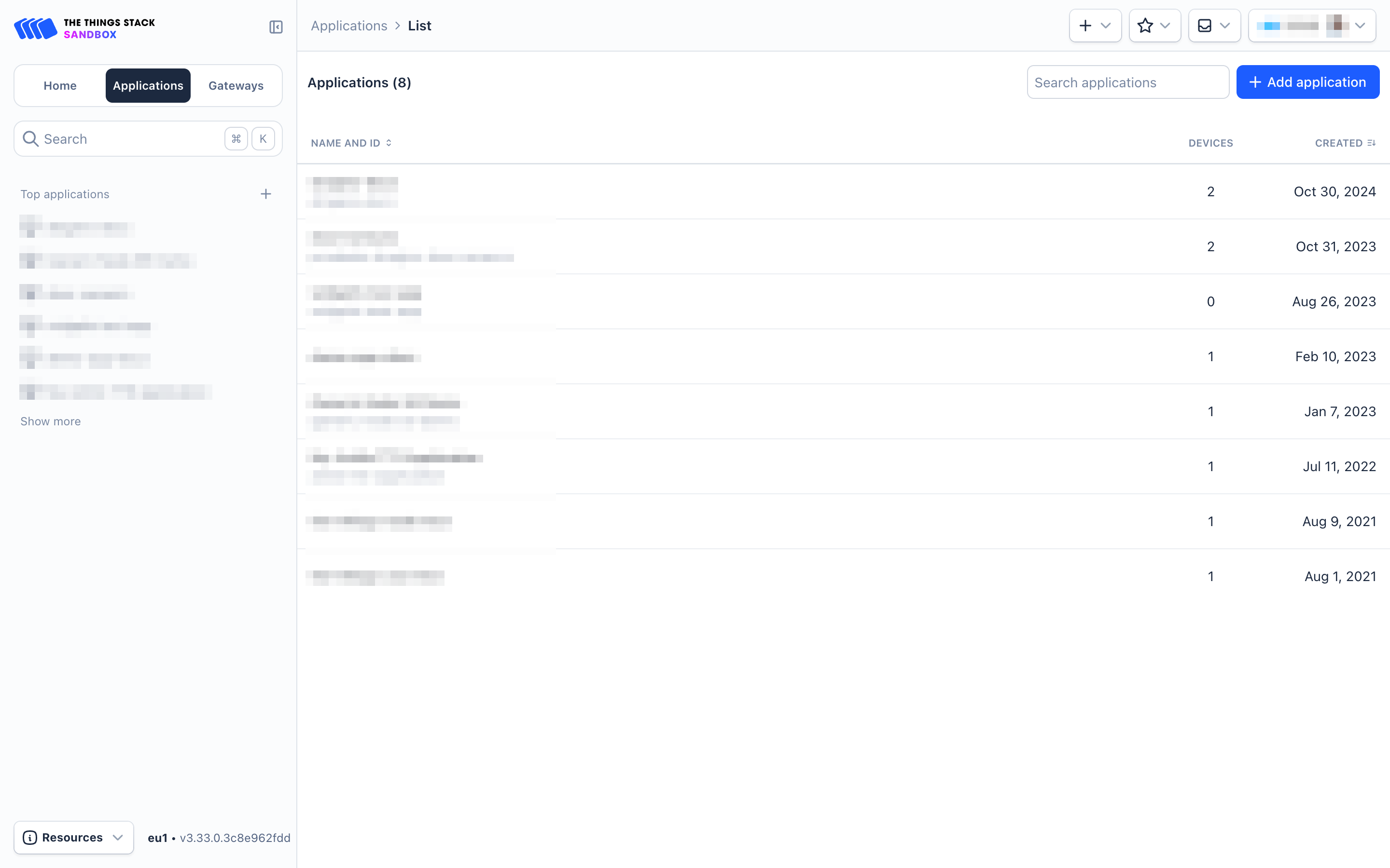
- On the left navigation, click Applications.
- Then click + Add Application button.
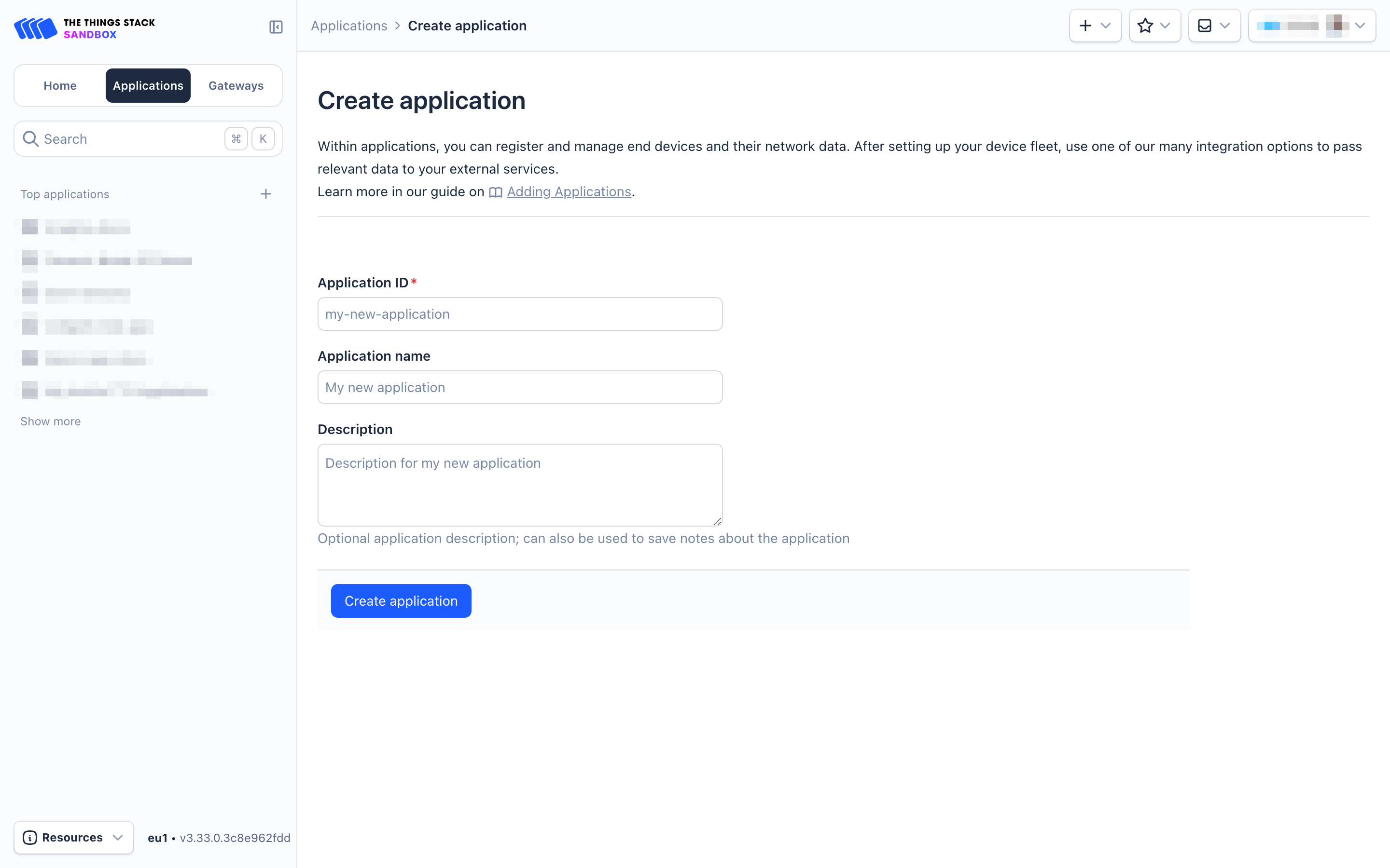
- On the Create Application page, configure the following:
- Application ID: Provide a unique identification for your application within The Things Stack.
- Application name: (optional) Provide a descriptive name.
- Description: (optional) Provide a description.
- Click on Create application button.
- Go to your application's page and click on the End devices in the left menu.
- On the End devices page, click on + Register end device.

- Two registration options are available:
- Using the LoRaWAN Device Repositoty
- Manual registration
4.2.1.2 Using the LoRaWAN Device Repository
- On the Register end device page:
- Select the option Select the end device in the LoRaWAN Device Repository under Input method.
- Select the End device brand, Model, Hardware version, Firmware version, and Profile (Region) from the respective dropdown lists.
- End device brand: Dragino Technology Co., Limited
- Model: LDS02 - Door Sensor
- Hardware ver: Unknown
- Firmware ver: 1.6
- Profile (Region): Select the region that matches your device.
- Select the Frequency plan that matches your device from the Frequency plan dropdown list.
- Enter the AppEUI in the JoinEUI field and click the Confirm button. If The Things Stack accepts the JoinEUI you provided, it will display the message 'This end device can be registered on the network.

- In the DevEUI field, enter the DevEUI.
- In the AppKey field, enter the AppKey.
- In the End device ID field, enter a unique name for your LDS02 within this application.
- Under After registration, select the View registered end device option.
- Click Register end device button.

- You will be navigated to the Device overview page.

- Click on the Live Data tab and then Power on the LDS02. It will first join The Things Stack network server. You can confirm this by looking for the Join-request and Join-accept messages. After successfully joining the network, the LDS02 will start sending uplink messages to The Things Stack, and you can see them in the Live Data panel.

4.3 Uplink Payload
4.3.1 Sensor value, Uplink via FPORT=10
The data is sent in the following cases:
- TDC (Transmit Time Interval-Keep Alive Interval), the default TDC is 24 hours, so this data is automatically sent every 24 hours.
- This data is sent each time the door is opened or closed, AT+DISALARM=0(default).
The uplink payload is a total of 10 bytes.
| Size (bytes) | 2 | 1 | 3 | 3 | 1 |
|---|---|---|---|---|---|
| Value | Door State & BAT | MOD Always:0x01 | Total open door events | Last door open | Alarm (Only used in LWL02) Always:0x00 |
Example:


This example uses the payload decoder in The Things Stack V3: https://github.com/dragino/dragino-end-node-decoder/tree/main/LDS02
Battery Info
Check the battery voltage:
Example 1: 0x0B88&3FFF = 2952mV
Example 2: 0xD152&3FFF = 4434mV
Status
Check the door state:
Example:
If the payload is: 0B: (0000 1011&1000 0000== 0), DOOR_OPEN_STATUS is 0(CLOSE)
If the payload is: D1: (1101 0001&1000 0000== 1), DOOR_OPEN_STATUS is 1(OPEN)
MOD
Check the working mode (MOD):
Example:
If the payload is: 01, the MOD is 1.
Total door open events
Get the total number of door open events:
Example:
If payload is: 00 00 93, the total is 147 events.
If payload is: 00 00 00, the total is 0 events.
Last door open duration(unit:min)
Get the last door open duration:
Example:
If the payload is: 00 00 25, the last door open duration is 37 minutes.
If payload is: 00 00 01, the last door open duration is 1 minute.
Alarm(Only used in LWL02) Always:0x00
Get alarm status.
Example:
If the payload is: 01: (0001 & 0001== 1), the alarm status is 1
If the payload is: 00: (0000 & 0001== 0), the alarm status is 0
4.3.2 EDC mode value, Uplink via FPORT=7
When EDC is enabled, LDS02 will send this data.
The uplink payload is a total of 5 bytes.
| byte | 2 | 3 |
|---|---|---|
| Value | EDC_MOD & BAT | Times |
Example:
AT+EDC=1,10


- AT+EDC=0,20


Battery Info
Check the battery voltage:
Ex1: (bytes[0]<<8 | bytes[1])&0x3FFF = 0x8C60&3FFF = 3168mV
Ex2: (bytes[0]<<8 | bytes[1])&0x3FFF = 0xD152&3FFF = 4434mV
EDC_MOD
This field is used to indicate whether the EDC mode packet sending condition is dependent on the number of door open accumulations or on the number of door close accumulations.
Ex1: bytes[0]&0x80 = 8C & 0x80 = 1000 0000(BIN), "OPEN".
Ex2: bytes[0]&0x80 = 0C & 0x80 = 0000 0000(BIN), "CLOSE".
Times
This field is used to display the number of open/closed events.
Ex1: 0x00000A(H) =10
Ex2: 0x000014(H) =20
4.4 Downlink Payload
| Downlink Control Type | Type Code | Downlink Payload Size (bytes) |
|---|---|---|
| TDC (Transmit Time Interval—Keep Alive Interval) | 0x01 | 4 |
| RESET | 0x04 | 2 |
| Set confirmed mode | 0x05 | 2 |
| Clear Counting | 0xA6 | 2 |
| Enable/Disable Alarm | 0xA7 | 2 |
| Control ADR/DR | 0xA8 | 3 |
| Set Alarm Timeout | 0xA9 | 4 |
The following image illustrates how to send a downlink payload from The Things Stack.

Type Code 0x01
If the payload is 0100003C, it means controlling the LDS02’s Keep Alive interval to 0x00003C = 60 seconds (s).
Type Code 0x04
If the payload is 0x04FF, it will reset the LDS02.
Type Code 0x05
0x05 00: Set uplink to LoRaWAN unconfirmed mode
0x05 01: Set uplink to LoRaWAN confirmed mode
Type Code 0xA6
Example: 0xA601 – Clear Counting
For the LDS02: Resets both the count number and time.
Type Code 0xA7
0xA701: Equivalent to AT+DISALARM=1
0xA700: Equivalent to AT+DISALARM=0
Type Code 0xA8
Format: 0xA8 aa bb
- aa: 1 – Enable ADR; 0 – Disable ADR (same as the AT+CADR command)
- bb: Set DR (same as AT+CDATARATE; only valid after ADR=0)
Example: 0xA80001 – Set ADR=0 and DR=1
Type Code 0xA9
See, Alarm Base Timeout for details.
4.5 Integrate with IoT Platforms
The Things Stack can be integrated with many IoT platforms, including ThingsEye and Datacake, for visualizing and analyzing data coming from the LDS02. Most of these IoT platforms also support sending downlinks to the LDS02.
4.5.1 Integrate with ThingsEye
The Things Stack application supports integration with ThingsEye.io. Once integrated, ThingsEye.io acts as an MQTT client for The Things Stack MQTT broker, allowing it to subscribe to upstream traffic and publish downlink traffic.
4.5.1.1 Configuring The Things Stack
We use The Things Stack Sandbox in this example:
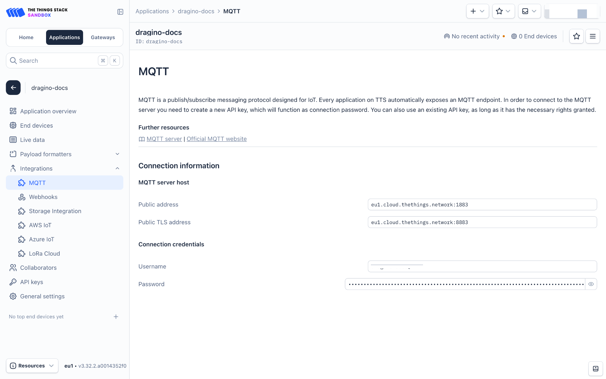
- In The Things Stack Sandbox, go to the Application for the LDS02 you added.
- Select MQTT under Integrations in the left menu.
- In the Connection information section, under Connection credentials, The Things Stack displays an auto-generated username. You can use it or provide a new one.
- Click the Generate new API key button to generate a password. You can view it by clicking on the visibility toggle/eye icon. The API key works as the password.
4.5.1.2 Configuring ThingsEye.io
The ThingsEye.io IoT platform is not open for self-registration at the moment. If you are interested in testing the platform, please send your project information to admin@thingseye.io, and we will create an account for you.
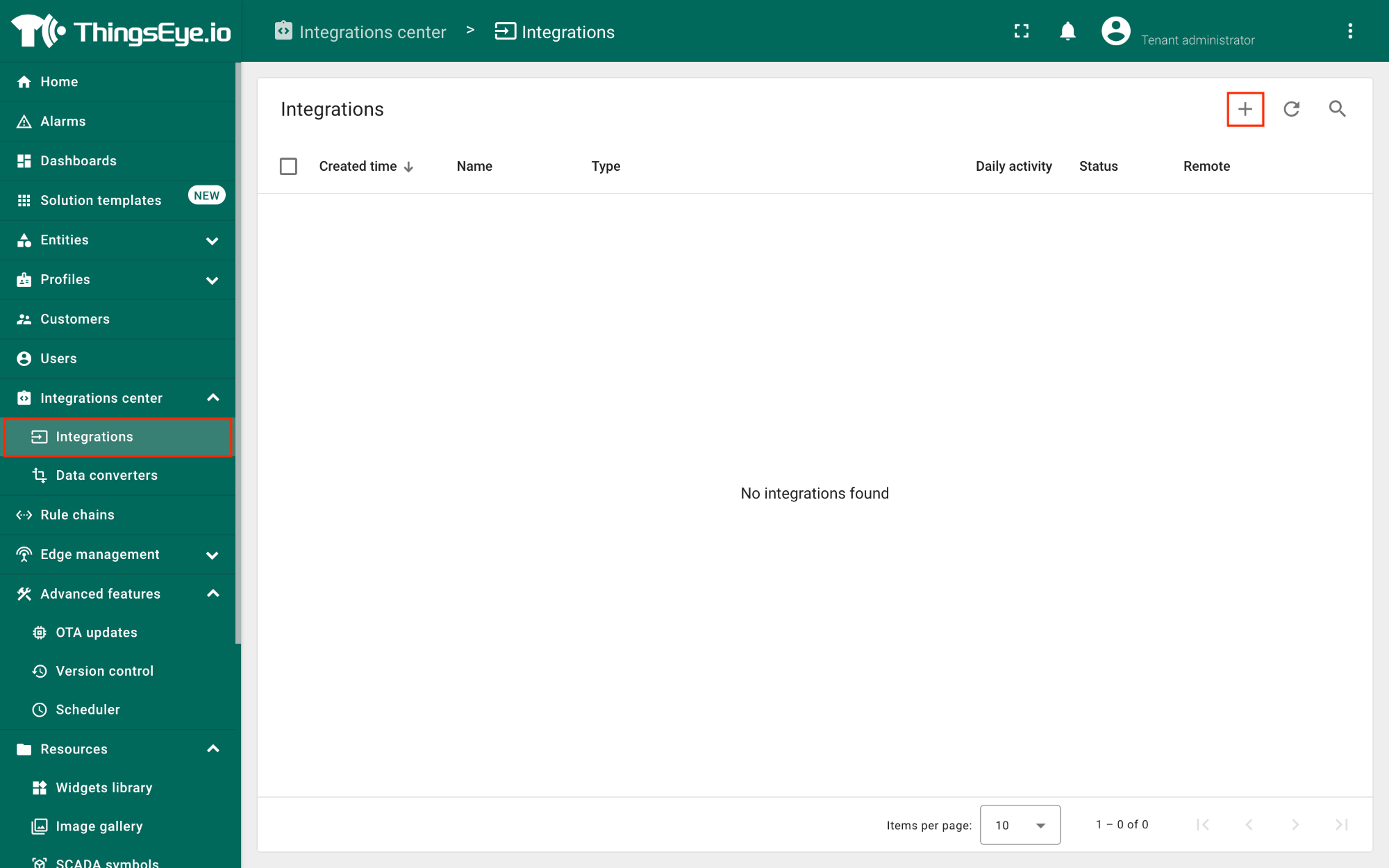
- Login to your ThingsEye.io account.
- Under the Integrations center, click Integrations.
- Click the Add integration button (the button with the + symbol).
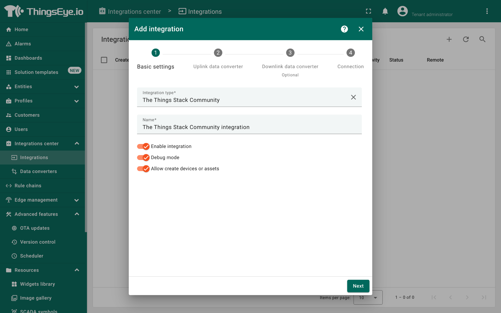
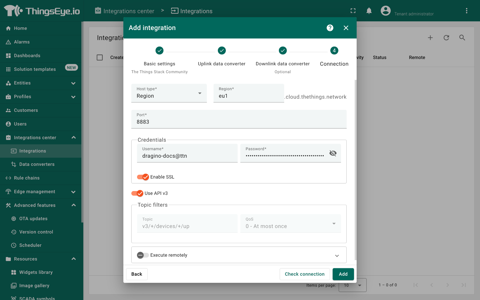
On the Add integration window, configure the following:
Basic settings:
- Select The Things Stack Community from the Integration type list.
- Enter a suitable name for your integration in the Name text box or keep the default name.
- Ensure the following options are turned on.
- Enable integration
- Debug mode
- Allow creating devices or assets
- Click the Next button. you will be navigated to the Uplink data converter tab.
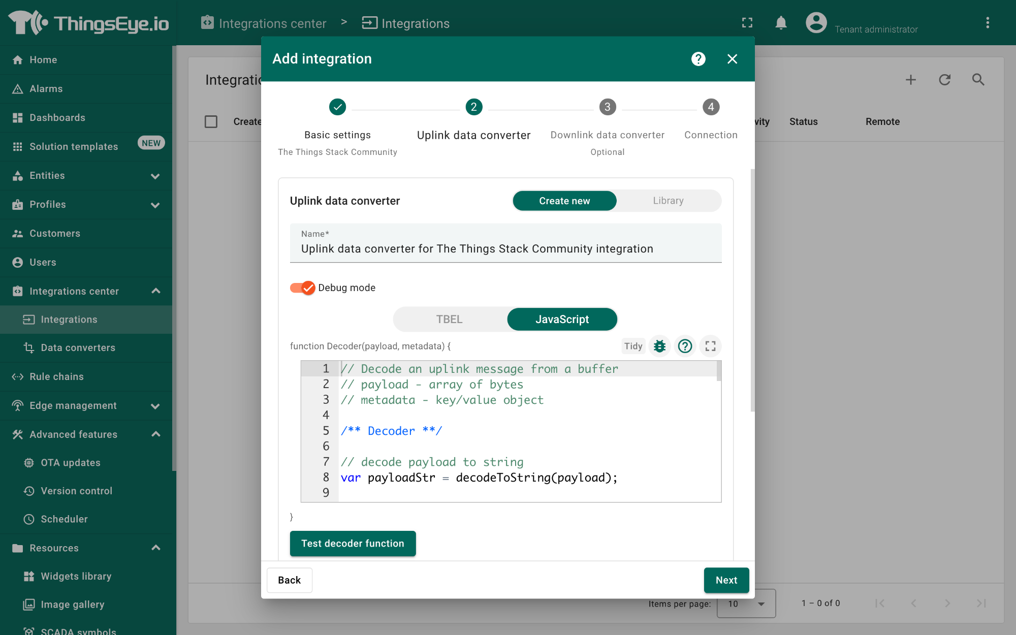
Uplink data converter:
- Click the Create new button if it is not selected by default.
- Enter a suitable name for the uplink data converter in the Name text box or keep the default name.
- Click the JavaScript button.
- Paste the uplink decoder function into the text area (first, delete the default code). The demo uplink decoder function can be found here.
- Click the Next button. You will be navigated to the Downlink data converter tab.
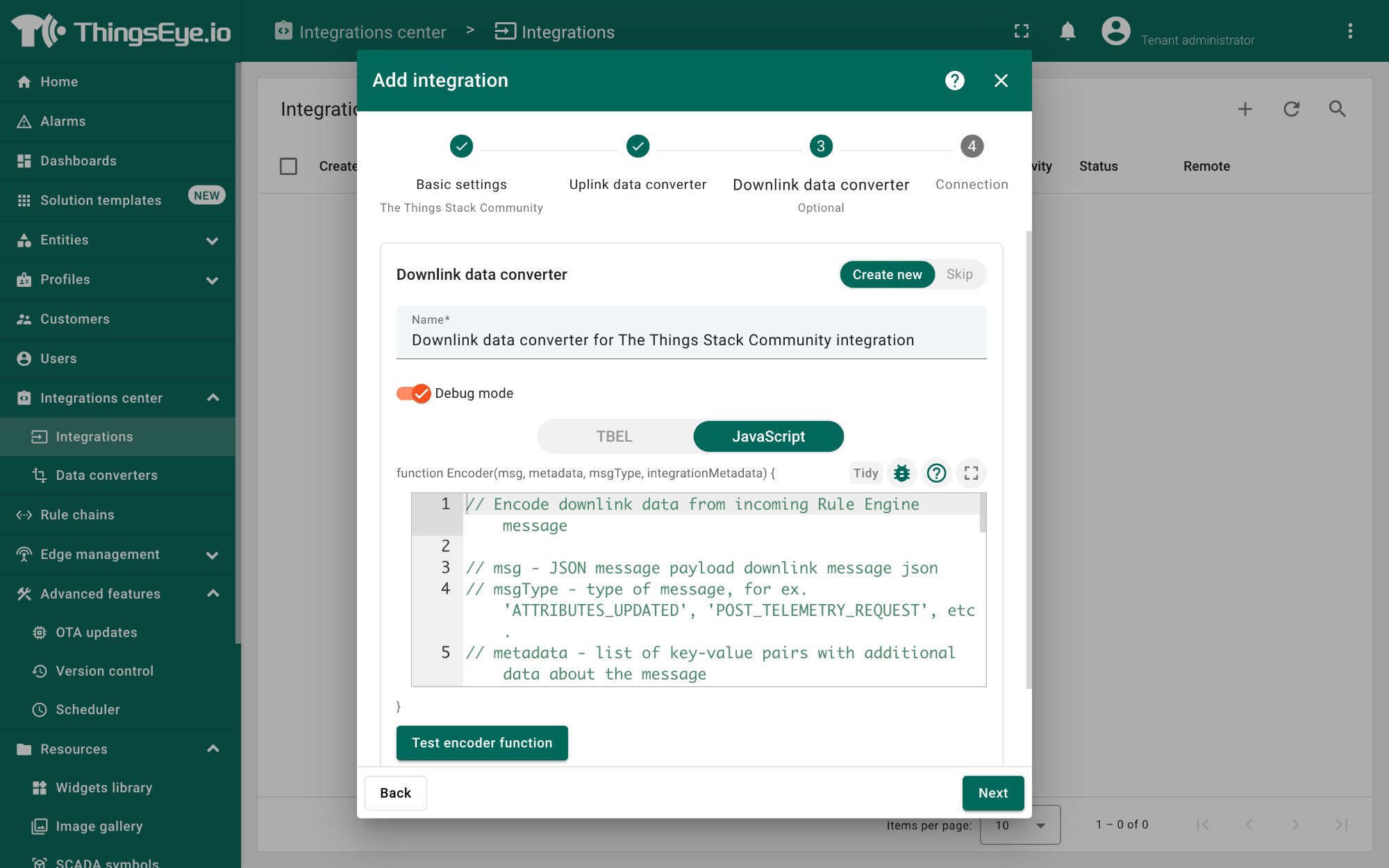
Downlink data converter (this is an optional step):
- Click the Create new button if it is not selected by default.
- Enter a suitable name for the downlink data converter in the Name text box or keep the default name.
- Click the JavaScript button.
- Paste the downlink decoder function into the text area (first, delete the default code). The demo downlink decoder function can be found here.
- Click the Next button. You will be navigated to the Connection tab.
Connection:
- Choose Region from the Host type.
- Enter the cluster of your The Things Stack in the Region textbox. You can find the cluster in the url (e.g., https://eu1.cloud.thethings.network/...).
- Enter the Username and Password of the MQTT integration in the Credentials section. The username and password can be found on the MQTT integration page of your The Things Stack account (see 4.5.1.1 Configuring The Things Stack).
- Click the Check connection button to test the connection. If the connection is successful, you will see the message saying Connected.
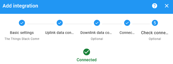
- Click the Add button.
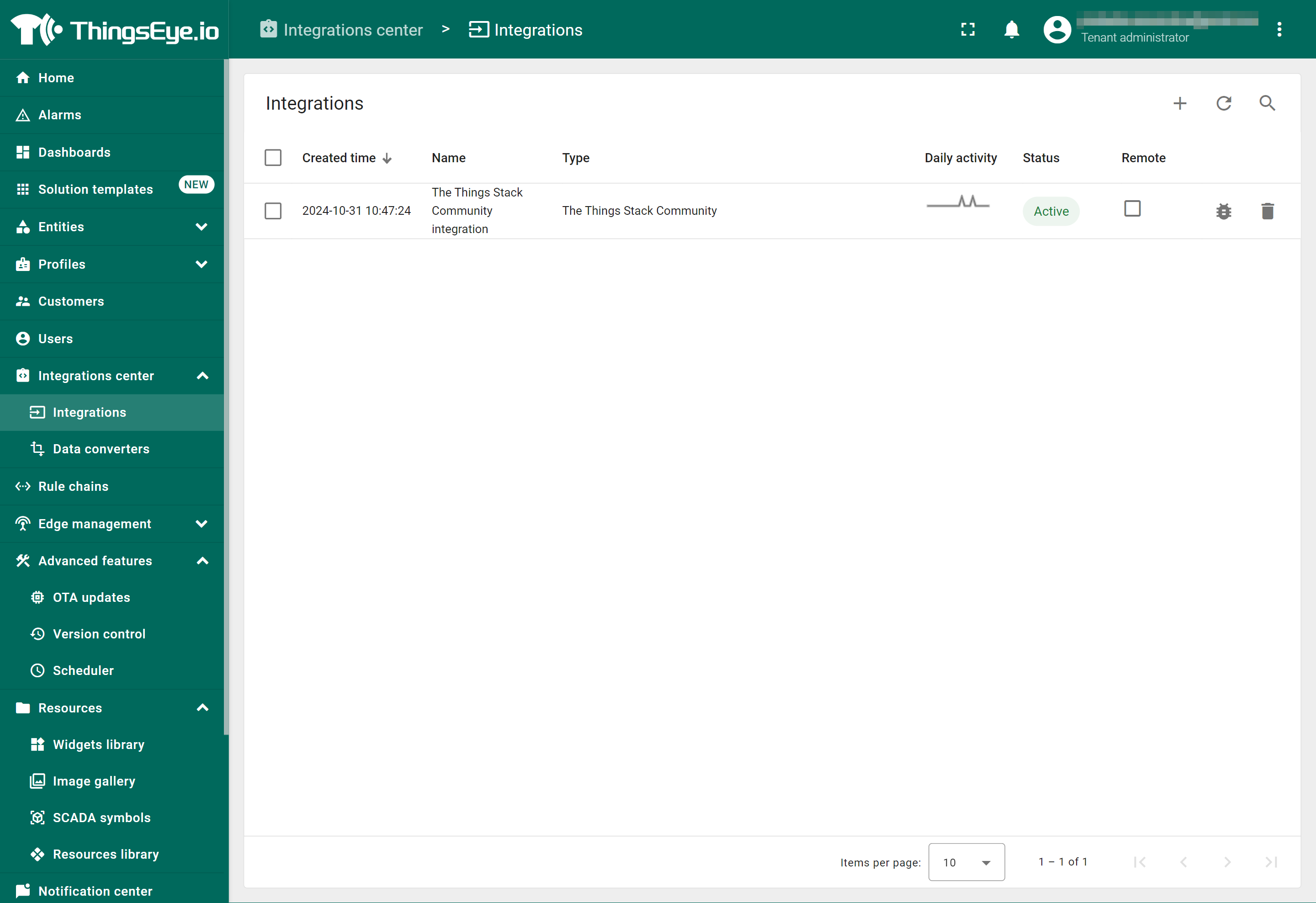
Your integration has been added to the Integrations list and will be displayed on the Integrations page. Check whether the status is shown as Active. If not, review your configuration settings and correct any errors.
4.5.1.3 Viewing integration details
Click on your integration from the list. The Integration details window will appear with the Details tab selected. The Details tab shows all the settings you have provided for this integration.
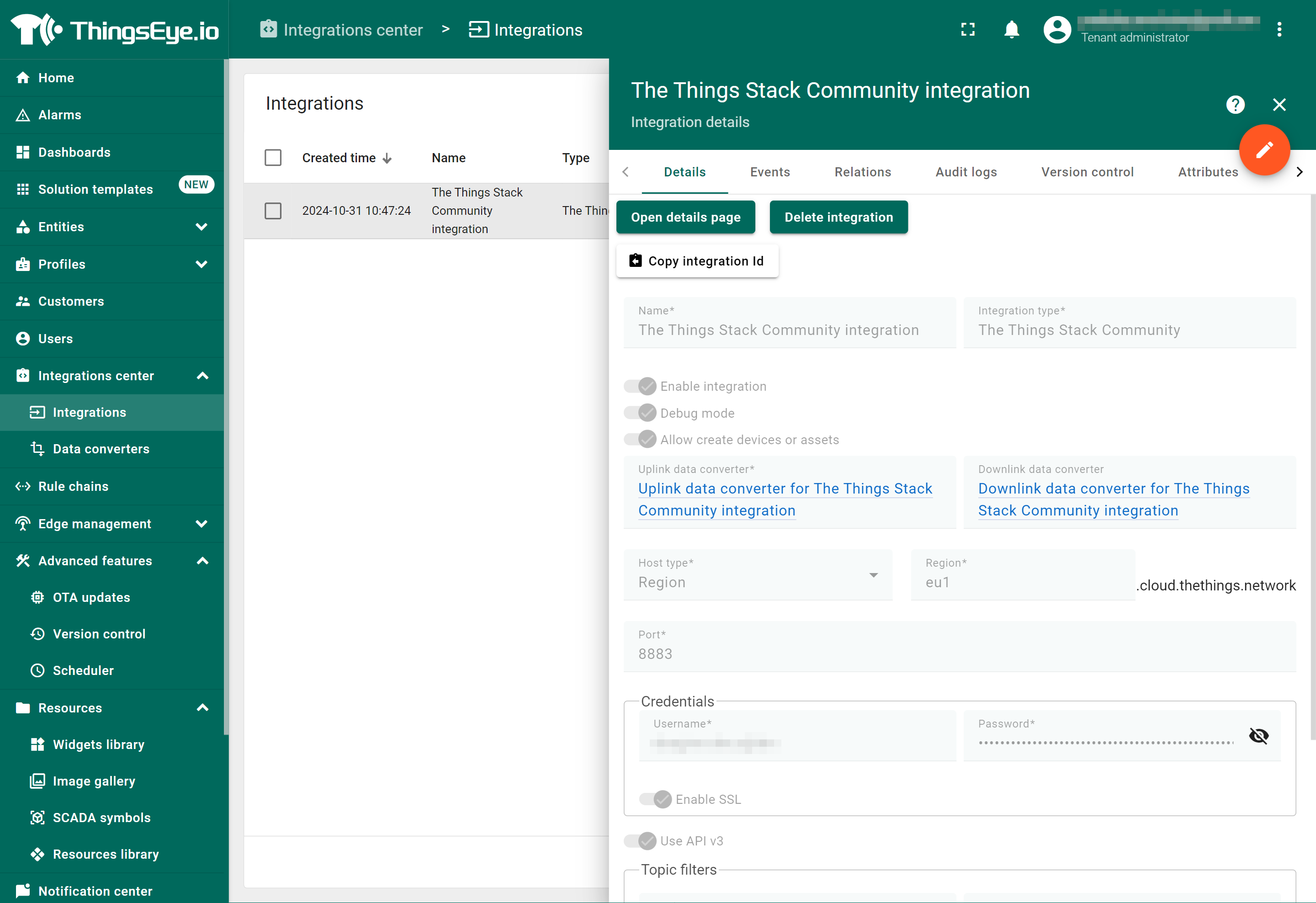
If you want to edit the settings you have provided, click on the Toggle edit mode button. Once you have done click on the Apply changes button.
4.5.1.4 Viewing events
The Events tab displays all the uplink messages from the LDS02.
- Select Debug from the Event type dropdown.
- Select the time frame from the time window.
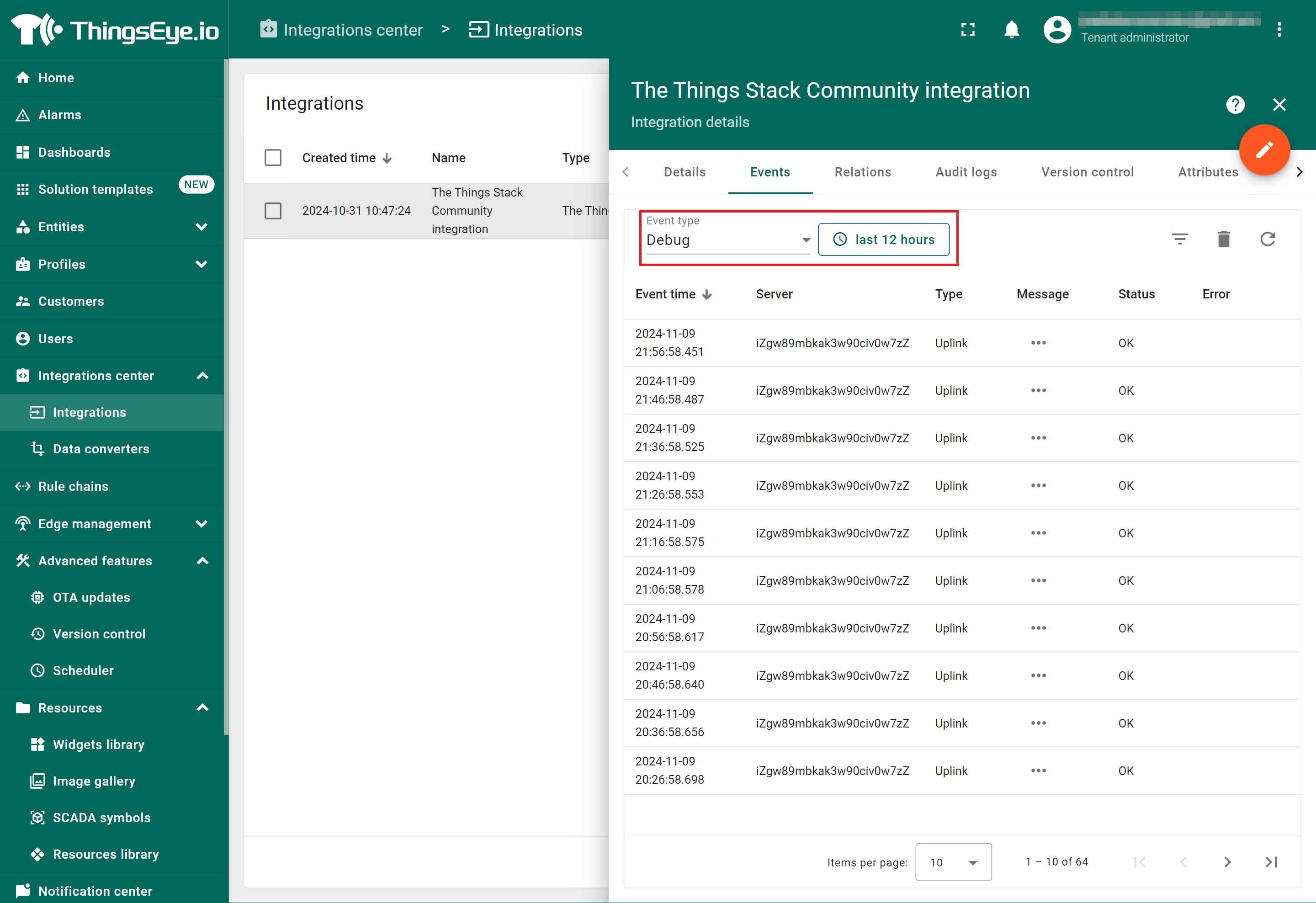
- To view the JSON payload of a message, click on the three dots (...) in the Message column of the desired message.

4.5.1.5 Deleting an integration
If you want to delete an integration, click the Delete integration button on the Integrations page.
4.5.1.6 Viewing sensor data on a dashboard
You can create a dashboard with ThingsEye to visualize the sensor data coming from the LDS02. The following image shows a dashboard created for the LDS02. See Creating a dashboard in ThingsEye documentation for more information.

4.5.2 Integrate with Datacake
Datacake is a multi-purpose, low-code IoT platform that allows you to integrate sensor data for visualization and analysis. With The Things Stack, you can easily create an integration with Datacake to forward your sensor data to the Datacake IoT platform.
4.5.2.1 Prerequisites
- The LDS02 device is joined to The Things Stack.
- Uplinks from the LDS02 device are being received by The Things Stack.
- A Datacake account (a free account is sufficient for this example).
4.5.2.2 Procedure
- In the Datacake workspace, on the left navigation, click Account Settings.
- Then click API Token.
- In the API Token tab, click the Copy button to copy the API token. You will need this API token when creating a webhook with The Things Stack.

To configure the Application to forward data to Datacake you will need to add integration. To add the Datacake integration, perform the following steps:
- In The Things Stack console, on the left navigation,
- First select your application (Applications -> <your application>)
- Then select Integrations -> Webhooks
- On the Webhooks page, click + Add Webhook button.

- On the Choose webhook template page, select Datacake.

- On the Setup webhook for Datacake page,
- Webhook ID: provide an unique identifier for this webhook
- Token: Paste the Datacake API Token when you copied from the Datacake Account Settings.
- Click on the Create Datacake webhook button.

Now the Webhook is created and displayed on the Webhooks page.

- In the Datacake workspace, on the left navigation, click Devices.
- On the Devices page, click +Add Device.

- On the Add Device window, click LoRaWAN option.
- Click on the Next button.

- On the Add LoRaWAN Device window, STEP 1, click on New Product from template option.
- Under Device Template, search lds02. Then click on Dragino LDS02 Door Sensor option.
- Click on the Next button.

- On the Add LoRaWAN Device window, STEP 2, under Network Server, click on The Things Stack V3 option.
- Click on the Next button.

- On the Add LoRaWAN Device window, STEP 3, under Add Devices, click Manual tab.
- In the DEVEUI textbox, enter your LDS02's 8 bytes DevEUI.
- In the NAME textbox, enter a suitable name to identify your LDS02.
- Click on the Next button.

- On the Add LoRaWAN Device window, STEP 4, select Individual device plans tab.
- Click Free option.
- Click on the Add 1 Device button.

- The device is now added to the Datacake workspace and is ready to receive uplinks from the LDS02 via The Things Stack.
- In the DEVICE column, click lds02.

You can see the pre-built dashboard from our template, displaying the LDS02's sensor data on various widgets.

4.6 Alarm Based on Timeout
The LDS02 can monitor the timeout for a status change. This feature can be used to monitor events such as a fridge being left open for too long, etc. You can configure this feature using either AT commands or a downlink command:
Using AT Commands:
- AT+TTRIG=1,30 --> When the status changes from closed to open, and the device remains in the open status for more than 30 seconds, the LDS02 will send an uplink packet. The Alarm bit (the lowest bit of the 10th byte of the payload) in this uplink packet is set to 1.
- AT+TTRIG=0,0 --> Default value, disables the timeout alarm.
Using Downlink Commands:
Command: 0xA9 aa bb cc
- A9: Command Type Code
- aa: Status to be monitored
- bb cc: Timeout
If the user sends 0xA9 01 00 1E, this is equivalent to AT+TTRIG=1,30.
Or
0xA9 00 00 00, this is equivalent to AT+TTRIG=0,0, which disables the timeout alarm.
4.7 EDC Mode(Since firmware v1.8.2)
Feature: Set EDC mode, when the cumulative number of opening/closing reaches the set count value, LDS02 will send the packet.
AT Command: AT+EDC
| Command Example | Function | Response/Parameters |
|---|---|---|
| AT+EDC? | Show current Settings | 0,0 (default) |
AT+EDC=aa,bb | aa: Set the open/close cumulative packet sending mode | 0: Set the close cumulative packet sending mode |
| bb: Set the cumulative count and send packets when the cumulative count is reached |
Downlink Command: 0X02
Format: Command Code (0x02) followed by 4 bytes.
Example:
- Downlink paylaod: 02 01 00 00 0A // AT+EDC=1,10 The LDS02 will send a packet for every 10 increases in the open_count.
- Downlink paylaod: 02 00 00 00 14 // AT+EDC=0,20 The LDS02 will send a packet for every 20 increases in the close_count.
Note: To use the EDC mode, you need to set AT+DISALARM=1(downlink payload: A701), so that LDS02 will send packets only when the TDC time and cumulative count reach the set value.
4.8 Set count value(Since firmware v1.8.2)
Feature: Set the initial count value.
AT Command: AT+SETCNT
| Command Example | Function | Response |
|---|---|---|
| AT+SETCNT=100 | Initialize the count value to 100. | OK |
Downlink Command: 0XAA
For normal mode: 0xAA xx xx xx
0xAA is the function code, and the next 3 bytes are the count value to be initialized.
- Example: Downlink Payload: AA 00 00 00 ---> AT+SETCNT=0 Set the open door count to 0.
For EDC mode: 0xAA aa xx xx xx
0xAA is the function code. aa sets how the EDC mode is accumulated (0x01: open; 0x00: close). and the next 3 bytes are the count values to be initialized.
- Example 1: Downlink Payload: AA 01 00 00 0A ---> AT+SETCNT=10 Set the door open count to 10.
- Example 2: Downlink Payload: AA 00 00 00 14 ---> AT+SETCNT=20 Set the door close count to 10.
5. Battery & How to replace
5.1 Battery Type and replace
The LDS02 is equipped with 2 x AAA LR03 batteries. If the batteries are running low (showing 2.1V on the platform), the user can buy generic AAA batteries and replace them.
Note:
- The LDS02 doesn't have any screws; you can use a nail to open it from the middle.
- Make sure the direction is correct when installing the AAA batteries.
Important Note: Ensure you use new AAA LR03 batteries, and that the battery surfaces are not damaged.
Example of AAA LR03 battery:

5.2 Power Consumption Analysis
Dragino battery-powered products all run in Low Power mode. Users can refer to the guidelines from this link to estimate battery life:
6. Use AT Commands
6.1 Access AT Commands
The LDS02 supports an AT command set. You can use a USB to TTL adapter to configure the LDS02 via AT commands, as shown below.

On the PC, the user needs to set the serial tool (such as PuTTY or SecureCRT) baud rate to 115200 to access the serial console of the LDS02. Below is the output for reference:
The AT command access password is 123456.

Each AT command needs to have an ENTER key pressed at the end before sending.
When entering the first command, the RED LED will turn on, and the user can now input AT commands. After entering all the required AT commands, input AT+CLPM=1 to set the device to Low Power mode, and the RED LED will turn off.
More details can be found in the AT Command Manual.
7. FAQ
7.1 How to upgrade the image?
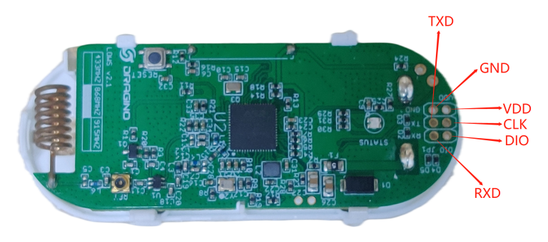
1. Connect the DAPLINK to the LDS02 as below:
3.3V<----->VDD
CLK<------>CLK
DIO<------>DIO (SWD)
GND<------>GND

2. Install PSoC Programmer 3.27.1
Download Link: PSoCProgrammer3.27.1
Then, use PSoC Programmer to upgrade the firmware (must use this version: PSoC Programmer 3.27.1).
3. Download Sensor Firmware
Downlink Firmware Location(same as LDS01) to prepare the update.
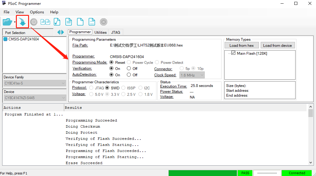
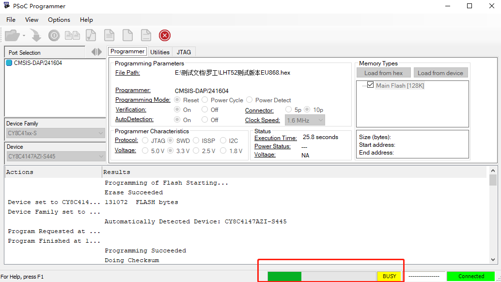
4. Upgrade Firmware
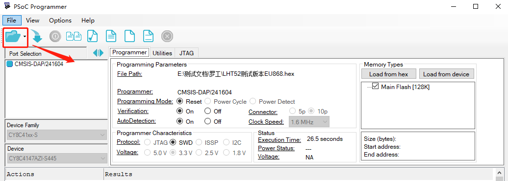
- Open PSoC Programmer, then select the default configuration.
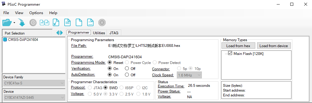
- Click the file icon to select the software to be burned.
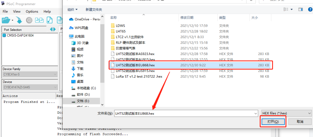
- Click the download icon, and the progress bar, as shown in the figure below, will appear. When PASS appears, it indicates that the burning was successful.
It is very important to press the reset button after the upgrade. This sets the device to work in Low Power mode.
If you change to a different LoRa frequency band/region, you need to use the AT+FDR command to restore the factory data after the program is successfully applied.
7.2 How to change the LoRa Frequency Bands/Region?
If you have the US915 frequency and want to change it to the AS923 frequency, you can follow the same instructions mentioned in the How to upgrade the image? section to upgrade the image. When downloading the image, select the required file.
7.3 Can I disable uplinks for each event to save battery life?
Yes, you can use one of the methods below:
Via AT Command:
AT+DISALARM=1 : The end node will only send packets during the TDC time.
AT+DISALARM=0 : The end node will send packets either during the TDC time or when there is a status change in the door sensor.
Via LoRaWAN downlink Command:
0xA701 : Equivalent to AT+DISALARM=1
0xA700 : Equivalent to AT+DISALARM=0
7.4 How can I change the Subband for LDS02?
Before v1.6 firmware:
LDS02 operates in Subband 2 by default in the AU915/US915 band. If the LoRaWAN server operates on another subband, LDS02 may have trouble joining the server. In this case, the user can use the AT command to change the subband. See the AT Command chapter for hardware connection details. Below are the steps to change the subband:
- Press the reset button.
- Send the password 123456.
- Send the command: AT+CFREQBANDMASK=0006 (use 0001 for Subband 1, 0002 for Subband 2, etc.).
- Press the reset button to restart and switch to the new subband.
Example output:
[3369]DRAGINO LWL01 Device
[3370]Frequency Band: US915 v1.5
[3373]OTAA
[3374]DevEui= 7896785455246354
[3377]class type A
[3379]freq mode intra
[3381]scan chn mask 0x0002 --> use subband 2
LM502:~# [10793]txDone
123456 --> ENTER PASSWORD
Correct Password
[105115]rxTimeOut
AT+CFREQBANDMASK=0020 --> Change to Subband6
OK
[3371]DRAGINO LWL01 Device
[3373]Frequency Band: US915 v1.5
[3376]OTAA
[3377]DevEui= 7896785455246354
[3380]class type A
[3382]freq mode intra
[3384]scan chn mask 0x0001 --> reboot and works on Subband1 now

Since firmware v1.6:
LDS02 works with the channel mask 0x0000, which covers all subbands. Therefore, there is no need to use AT commands to change the subband, and it will work for every subband.
7.5 My sensor worked for Helium AU915 before, but now it doesn't work. Why?
This is a sub-band issue. See chapter 7.4. Helium changed the sub-band for AU915 from subband 2 to subband 6, which caused the sensor to stop working.
7.6 Why do I see different working temperatures for the device?
The working temperature range of the device depends on the battery the user chooses.
- A standard AAA battery can support a working range of -10°C to 50°C.
- A special AAA battery can support a working range of -40°C to 60°C. For example, Energizer L92
7.7 The device keeps rejoining the network and is not working properly
Cause of the problem:
When the DR of AU915 and AS923 is 2 or the DR of US915 is 0, upon receiving the MAC Command from the server, the node will enter deep sleep and will not send packets because the attached MAC answer exceeds the number of bytes.
Solution:
- Manually restart the device, then downlink 21 03 (only needs to be set once to be effective).
- Manually restart the device, then set AT+RPL=3 (only needs to be set once to be effective).
- Update the firmware to version v1.8 or above.
8. Ordering Information
Part Number: LDS02-XXX
XXX: The default frequency band
- EU433: frequency bands EU433
- EU868: frequency bands EU868
- KR920: frequency bands KR920
- CN470: frequency bands CN470
- AS923: frequency bands AS923
- AU915: frequency bands AU915
- US915: frequency bands US915
- IN865: frequency bands IN865
- CN779: frequency bands CN779
9. Packaging Information
Package Includes:
LDS02 x 1
Dimension and weight:
Device Size: 69.2 x 29.2 x 14.8 mm
10. Support
- Support is provided Monday to Friday, from 09:00 to 18:00 GMT+8. Due to different time zones, we cannot offer live support. However, your questions will be answered as soon as possible during the aforementioned schedule.
- Please provide as much information as possible regarding your inquiry (product models, a clear description of the problem, steps to replicate it, etc.) and send an email to support@dragino.com.