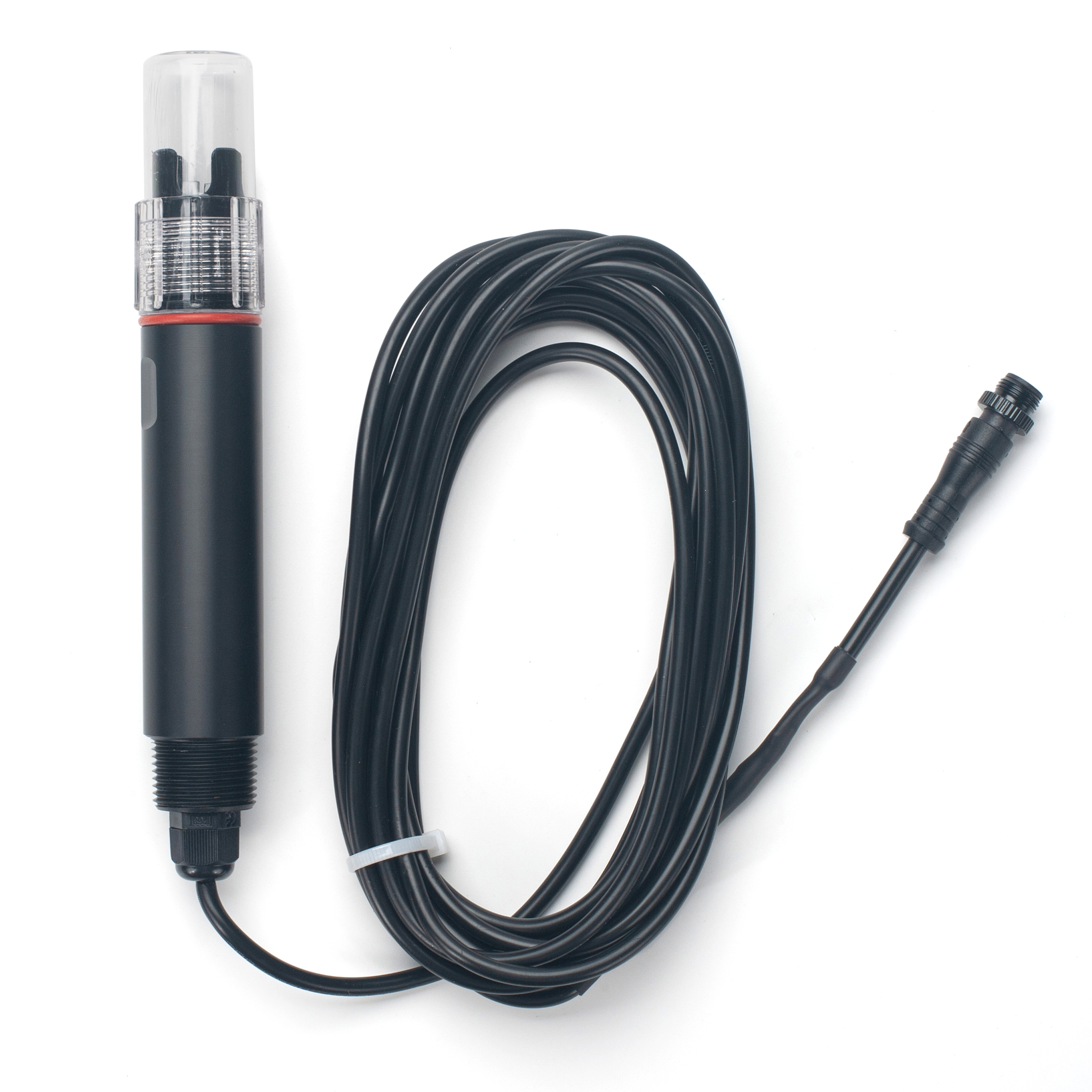
DR-ECK1.0, DR-ECK10.0, DR-EC200 -- EC Digital Electrode Sensor
1. Introduction
1.1 Specification:
-
Power Input: DC7~30V
-
Power Consumption : < 0.5W
-
Interface: RS485. 9600 Baud Rate
-
EC Range & Resolution:
- ECK1.0 : 0 ~ 2,000 μS/cm ; Resolution: 1 μS/cm
- ECK10.0 : 10 ~ 20,000 μS/cm ; Resolution: 10 μS/cm
- EC200 : 1 ~ 200,000 μS/cm ; Resolution: 1 μS/cm
-
Probe Electrode:
- ECK1.0 : K1 Electrode
- ECK10.0 : K10 Electrode
- EC200 : FourElectrode
-
EC Accuracy: ±1% FS
-
Salinity measurement range
- EC200 : 0~70PSU Resolution: 0.1PSU
-
Temperature measurement range
- ECK1/ECK10:-20~+60°C; Resolution: 0.1°C
- EC200 :-5~+80°C; Resolution: 0.1°C
-
Temperature Accuracy:±0.5 °C
-
Temperature compensation range
- ECK1/ECK10: 0~+60°C (default compensation temperature 25°C)
- EC200:-5~+80°C (default compensation temperature 25°C)
-
Temperature compensation coefficient: Default 0.2
-
Working environment:
- Ambient Temperature: 0--60°C
- Relative Humidity: <85% RH(Specifically refers to the cable male and female)
- EC200 Continuous monitoring of cross-section water quality, aquaculture, sewage treatment, environmental protection, pharmaceuticals, food, tap water, seawater and other high conductivity environments
-
IP Rated: IP68
-
Max Pressure: 0.6MPa
-
Wire length: 5 meters
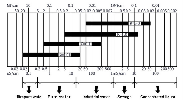
1.2 Application for Different Range
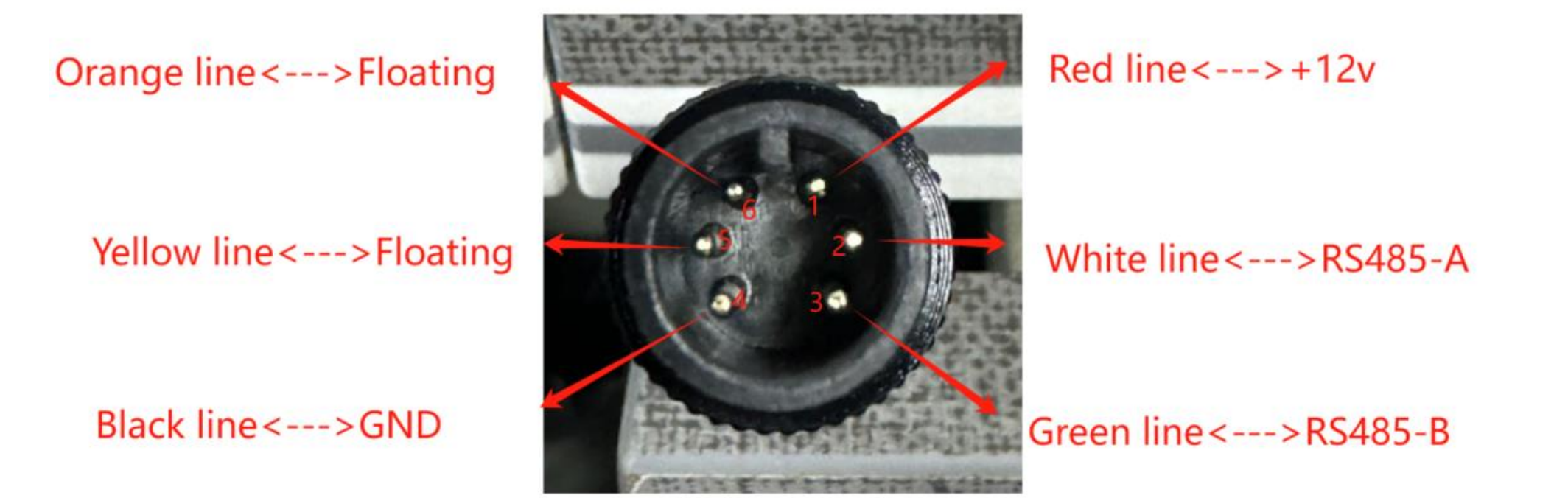
1.3 Wiring
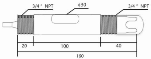
1.4 Mechinical Drawing
ECK1 and ECK10
EC200
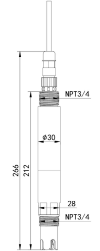
1.5 Installation
Electrode installation form:
A: Side wall installation
B: Top flange installation
C: Pipeline bend installation
D: Pipeline bend installation
E: Flow-through installation
F: Submerged installation
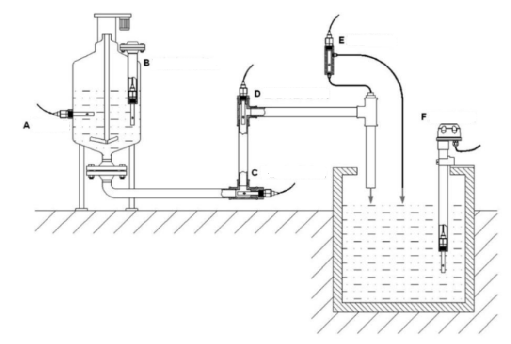
Several common installation methods of electrodes
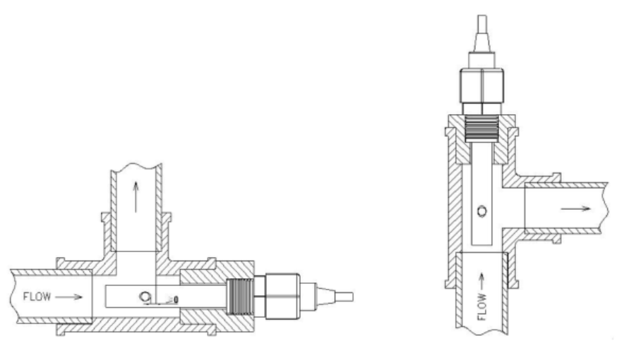
When installing the sensor on site, you should strictly follow the correct installation method shown in the following picture. Incorrect installation method will cause data deviation.
A. Several common incorrect installation methods
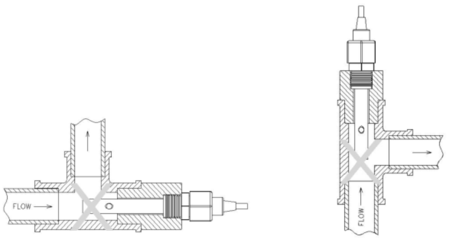
Error cause: The electrode joint is too long, the extension part is too short, the sensor is easy to form a dead cavity, resulting in measurement error.
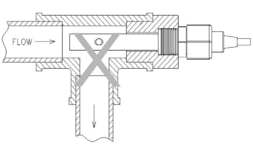
Error cause: Measurement error or instability may occur due to water flow not being able to fill the pipe or air accumulation at high altitudes.
B. Correct installation method
1.6 Maintenance
-
The equipment itself generally does not require daily maintenance. When an obvious fault occurs, please do not open it and repair it yourself, and contact us as soon as possible.
-
If the electrode is not used for a long time, it can generally be stored in a dry place, but it must be placed (stored) in distilled water for several hours before use to activate the electrode. Electrodes that are frequently used can be placed (stored) in distilled water.
-
Cleaning of conductivity electrodes: Organic stains on the electrode can be cleaned with warm water containing detergent, or with alcohol. Calcium and magnesium precipitates are best cleaned with 10% citric acid. The electrode plate or pole can only be cleaned by chemical methods or by shaking in water. Wiping the electrode plate will damage the coating (platinum black) on the electrode surface.
-
The equipment should be calibrated before each use. It is recommended to calibrate it every 3 months for long-term use. The calibration frequency should be adjusted appropriately according to different application conditions (degree of dirt in the application, deposition of chemical substances, etc.).
1.7 RS485 Commands
RS485 signal (K1 default address 0x12; K10 default address 0x11): Standard Modbus-RTU protocol, baud rate: 9600; check bit: none; data bit: 8; stop bit: 1
The following commands are by default for ECK1/ECK10. Please note that EC200 has different commands.
1.7.1 Query address
send:
| Original address | Function code | Address high | Address low | Quantity high | Quantity low | CRC16 low | CRC16 high |
|---|---|---|---|---|---|---|---|
| 0XFE | 0X03 | 0X00 | 0X50 | 0X00 | 0X00 | 0X51 | 0XD4 |
If you forget the original address of the sensor, you can use the broadcast address 0XFE instead. When using 0XFE, the host can only connect to one slave, which can be used as a method of address query.
response:
| New address | Function code | Data length | CRC16 low | CRC16 high |
|---|---|---|---|---|
| 0X01 | 0X03 | 0X00 | 0X20 | 0XF0 |
1.7.2 Change address
For example: Change the address of the sensor with address 1 to 2, master → slave
| Original address | Function code | Address high | Address low | Quantity high | Quantity low | CRC16 low | CRC16 high |
|---|---|---|---|---|---|---|---|
| 0X01 | 0X06 | 0X00 | 0X50 | 0X00 | 0X02 | 0X08 | 0X1A |
If the sensor receives correctly, the data is returned along the original path.
Note: If you forget the original address of the sensor, you can use the broadcast address 0XFE instead. When using 0XFE, the host can only connect to one slave, and the return address is still the original address, which can be used as a method of address query.
1.7.3 Modify intercept
send:
| Address | Function code | Address high | Address low | Quantity high | Quantity low | CRC16 low | CRC16 high |
|---|---|---|---|---|---|---|---|
| 0X01 | 0X06 | 0X00 | 0X23 | 0X00 | 0X01 | 0XF8 | 0X07 |
Change the intercept of the sensor with address 1 to 10 (default 0), which is 0X000A in the command.
response:
| Address | Function code | Address high | Address low | Quantity high | Quantity low | CRC16 low | CRC16 high |
|---|---|---|---|---|---|---|---|
| 0X01 | 0X06 | 0X02 | 0X00 | 0X00 | 0X0A | 0X38 | 0X8F |
1.7.4 Query data
Query the data (EC,temperature) of the sensor (address 11), host → slave
| Address | Function code | Starting register address high | Starting register address low | Register length high | Register length low | CRC16 low | CRC16 high |
|---|---|---|---|---|---|---|---|
| 0X11 | 0X03 | 0X00 | 0X00 | 0X00 | 0X02 | 0XC6 | 0X9B |
If the sensor receives correctly, the following data will be returned, slave → host
| Address | Function code | Data length | Register 0 Data high | Register 0 Data low | Register 1 Data high | Register 1 Data low | CRC16 low | CRC16 high |
|---|---|---|---|---|---|---|---|---|
| 0X11 | 0X03 | 0X04 | 0X02 | 0XAE | 0X01 | 0X64 | 0X8B | 0XD0 |
The address of the EC K10 sensor is 11
The query data command is 11 03 00 00 00 02 C6 9B
For example, the returned data is 11 03 04 02 AE 01 64 8B D0. 02 AE is converted to decimal 686, K=10, EC: 6860uS/cm,temperature: 35.6℃ Convert the returned data to decimal and divide by 10.
Query the data (EC,temperature) of the sensor (address 11), host → slave
| Address | Function code | Starting register address high | Starting register address low | Register length high | Register length low | CRC16 low | CRC16 high |
|---|---|---|---|---|---|---|---|
| 0X12 | 0X03 | 0X00 | 0X00 | 0X00 | 0X02 | 0XC6 | 0XA8 |
If the sensor receives correctly, the following data will be returned, slave → host
| Address | Function code | Data length | Register 0 Data high | Register 0 Data low | Register 1 Data high | Register 1 Data low | CRC16 low | CRC16 high |
|---|---|---|---|---|---|---|---|---|
| 0X12 | 0X03 | 0X04 | 0X02 | 0XAE | 0X01 | 0X64 | 0XB8 | 0XD0 |
The address of the EC K1 sensor is 12
The query data command is 12 03 00 00 00 02 C6 A8
For example, the returned data is 12 03 04 02 AE 01 64 B8 D0. 02 AE is converted to decimal 686, K=1, EC: 686uS/cm,temperature: 35.6℃ Convert the returned data to decimal and divide by 10.
EC200
| Address | Function code | Register Address | Register length | CRC16 low | CRC16 high |
|---|---|---|---|---|---|
| 0X01 | 0X03 | 0X00 0X00 | 0X00 0X04 | 0XC5 | 0XC8 |
response:
| Address | Function code | Number of valid bytes | Register contents | CRC16 low | CRC16 high |
|---|---|---|---|---|---|
| 0X01 | 0X03 | 0X08 | 0X00 0X00 0X1E 0XEF 0X01 0X14 0X00 0X2B | 0X42 | 0X59 |
Conductivity calculation: 0X1EEF=7919=>Conductivity=7919μS/cm Temperature calculation: 0X0114=276=>Temperature=27.6℃ Salinity calculation: 0X002b=43=>Salinity=4.3PSU
1.7.5 Calibration Method
ECK1 and ECK10.0
This device uses one-point calibration, and you need to prepare a known E standard solution. When mileage K=1, 12000 uses 1413μS/cm standard solution, and when mileage K=10, 1020000 uses 12.88mS/cm standard solution.
The calibration steps are as follows:
(1) Place the electrode in distilled water and clean it. When mileage 1~2000 uses 1413μS/cm standard solution, enter the following calibration command after the data is stable.
| Address | Function code | Address high | Address low | Quantity high | Quantity low | Data length | Data | CRC16 low | CRC16 high |
|---|---|---|---|---|---|---|---|---|---|
| 0X12 | 0X10 | 0X00 | 0X26 | 0X00 | 0X02 | 0X04 | 0X00 0X00 0X37 0X32 | 0XBD | 0XFC |
1413*10 gives 0X00003732
response:
| Address | Function code | Address high | Address low | Quantity high | Quantity low | CRC16 low | CRC16 high |
|---|---|---|---|---|---|---|---|
| 0X12 | 0X10 | 0X00 | 0X26 | 0X00 | 0X02 | 0XA2 | 0XA0 |
(2) Place the electrode in distilled water to clean it. Use 12.88mS/cm standard solution for the range of 10~20000. After the data is stable, enter the following calibration command
| Address | Function code | Address high | Address low | Quantity high | Quantity low | Data length | Data | CRC16 low | CRC16 high |
|---|---|---|---|---|---|---|---|---|---|
| 0X11 | 0X10 | 0X00 | 0X26 | 0X00 | 0X02 | 0X04 | 0X00 0X01 0XF7 0X20 | 0X33 | 0X75 |
12880*10 gives 0X01F720
response:
| Address | Function code | Address high | Address low | Quantity high | Quantity low | CRC16 low | CRC16 high |
|---|---|---|---|---|---|---|---|
| 0X11 | 0X06 | 0X00 | 0X26 | 0X00 | 0X02 | 0XEB | 0X50 |
EC200
For the device with address 01, use 1413uS/cm standard solution to calibrate the first point. Send frame: 1413. Convert hexadecimal to 585. Write 0001, 00 00, 0585 to 0x0120, 0x0121, 0x0122 respectively.
| Address | Function code | Register Address | Register length | Data length | Register contents | CRC16 low | CRC16 high |
|---|---|---|---|---|---|---|---|
| 0X01 | 0X10 | 0X01 0X20 | 0X00 0X03 | 0X06 | 0X00 0X01 0X00 0X00 0X05 0X85 | 0X1c | 0X25 |
response:
| Address | Function code | Register Address | Register length | Data length | CRC16 low | CRC16 high |
|---|---|---|---|---|---|---|
| 0X01 | 0X10 | 0X01 0X02 | 0X00 0X03 | 0X06 | 0X80 | 0X3e |
Use 111310uS/cm standard solution to calibrate the second point and send the frame: 111310 is converted into hexadecimal 1b2ce, and 0002, 0001,b2 ce are written to 0x0120, 0x0121, and 0x0122 respectively.
| Address | Function code | Register Address | Register length | Data length | Register contents | CRC16 low | CRC16 high |
|---|---|---|---|---|---|---|---|
| 0X01 | 0X10 | 0X01 0X20 | 0X00 0X03 | 0X06 | 0X00 0X02 0X00 0X01 0Xb2 0Xce | 0X3e | 0X22 |
response:
| Address | Function code | Register Address | Register length | Data length | CRC16 low | CRC16 high |
|---|---|---|---|---|---|---|
| 0X01 | 0X10 | 0X01 0X02 | 0X00 0X03 | 0X06 | 0X80 | 0X3e |