WSC2-Compact-NS – NB-IoT Weather Station Kit
1. Introduction
1.1 What is WSC2-Compact-NS NB-IoT Weather Station Kit
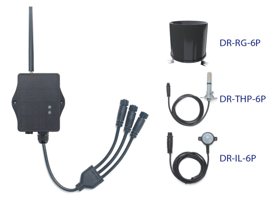
The Dragino WSC2-Compact-NS is a solar-powered NB-IoT Weather Station Kit designed for measuring atmospheric conditions. It provides weather data for agriculture, weather forecasting, environmental monitoring and climate research.
The WSC2-Compact-NS can connect to a 3-in-1 temperature, humidity and air pressure sensor, an illumination sensor and a tipping bucket rain gauge. It also supports optional wind speed and direction, soil moisture and EC sensors.
The transmitter collects sensor values and uploads them to an IoT server through an NB-IoT network. It supports MQTT, MQTTs, TCP, UDP and CoAP.
WSC2-Compact-NS supports Bluetooth v5.1 remote configuration and firmware update. It is powered by a solar panel and a built-in 3000mAh rechargeable Li-ion battery for long-term outdoor use.
Make sure NB-IoT coverage is available at the installation location.
1.2 Features
- NB-IoT Bands: B1/B2/B3/B4/B5/B8/B12/B13/B17/B18/B19/B20/B25/B28/B66/B70/B85 @H-FDD
- Uplink via MQTT, MQTTs, TCP, UDP or CoAP
- Multiple payload types: General JSON, HEX
- Supports multiple samplings in one uplink
- Supports interrupt and counting modes for the rain gauge
- Supports Bluetooth v5.1 remote configuration and firmware update
- AT commands and downlinks to change configuration
- Nano SIM card slot
- IP66 waterproof enclosure
- Solar panel + 3000mAh rechargeable Li-ion battery
1.3 3-in-1 Sensor: DR-THP-6P

Temperature:
- Range: -40 to +80°C
- Accuracy: ±0.2°C @ 0 to 90°C
- Resolution: 0.1°C
- Long-term shift: <0.03°C/year
Humidity:
- Range: 0 to 99.9% RH
- Accuracy: ±2% RH (0 to 100% RH)
- Resolution: 0.01% RH
- Long-term shift: <0.25% RH/year
Air Pressure:
- Accuracy: ±0.1kPa @ 25°C, 101kPa
- Range: 300 to 1100hPa
1.4 Illumination Sensor: DR-IL-6P

- Based on BH1750 illumination sensor
- Resolution: 1lx
- Range: 0 to 65535lx
- Operating temperature: -40°C to 85°C
- Cable length: 50cm
1.5 Rain Gauge: DR-RG-6P
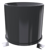
- Rain-bearing diameter: 200mm; blade angle: 40° to 45°
- Range: 0 to 100mm/day by default
- Resolution: 0.1mm
- Rain intensity range: 0.01 to 4mm/min
- Output signal: pulse signal
- Cable specification: 2m, 2-wire system
1.6 NB-IoT Specification
Common DC Characteristics:
- Supply Voltage: 2.1v ~ 3.6v
- Operating Temperature: -40 ~ 85°C
NB-IoT Spec:
NB-IoT Module: BC660K-GL
Support Bands:
- B1 @H-FDD: 2100MHz
- B2 @H-FDD: 1900MHz
- B3 @H-FDD: 1800MHz
- B4 @H-FDD: 2100MHz
- B5 @H-FDD: 860MHz
- B8 @H-FDD: 900MHz
- B12 @H-FDD: 720MHz
- B13 @H-FDD: 740MHz
- B17 @H-FDD: 730MHz
- B18 @H-FDD: 870MHz
- B19 @H-FDD: 870MHz
- B20 @H-FDD: 790MHz
- B25 @H-FDD: 1900MHz
- B28 @H-FDD: 750MHz
- B66 @H-FDD: 2000MHz
- B70 @H-FDD: 2000MHz
- B85 @H-FDD: 700MHz
Battery:
- Li-ion battery
- Capacity: 3000mAh
- Self Discharge: <1% / Year @ 25°C
- Max continuously current: 130mA
- Max boost current: 2A, 1 second
Power Consumption
- STOP Mode: 10uA @ 3.3v
- Max transmit power: 350mA @ 3.3v
1.7 Sleep Mode and Working Mode
Deep Sleep Mode: The sensor does not activate the NB-IoT module. This mode is used for storage and shipping to save battery power.
Working Mode: The sensor attaches to the configured cellular network and sends sensor data to the IoT server. Between sampling and transmission cycles, the sensor enters low-power mode.
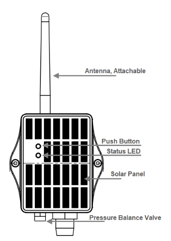
1.8 Button & LEDs
| Behavior on ACT | Function | Action |
|---|---|---|
 1~3s 1~3s | Send an uplink | If the sensor is attached to the NB-IoT network, it sends an uplink and the blue LED blinks once. BLE is also activated for configuration. |
| >3s | Activate device | The green LED blinks five times. The device enters OTA mode for 12 seconds and then starts attaching to the network. The green LED stays on for five seconds after a successful attachment. |
 x5 x5 | Deactivate device | The red LED stays on for five seconds, indicating that the device has entered Deep Sleep Mode. |
1.9 BLE Connection
WSC2-Compact-NS supports BLE remote configuration and firmware update. BLE is activated when the button is pressed, or when the device is powered on or reset. BLE turns off after 60 seconds without activity.
1.10 Pin Mapping, Switch and SIM Direction
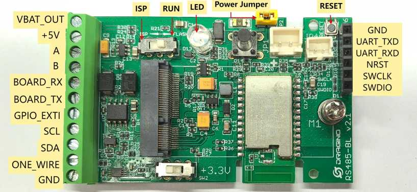
Install the Nano SIM card before powering on the device. See General Configure for NB/NS Models.
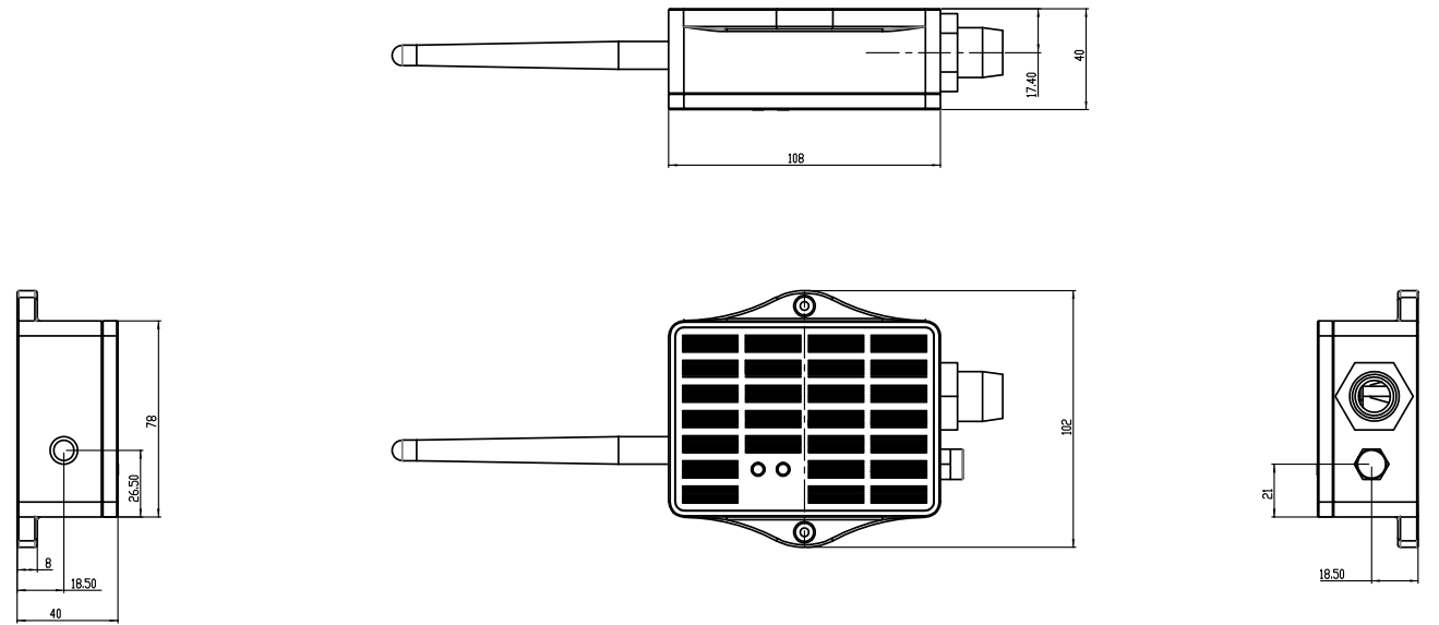
1.11 Mechanical (for NS Version)
2. Use WSC2-Compact-NS to Communicate with IoT Server
2.1 Send Data via NB-IoT Network
The pre-loaded firmware reads the connected weather sensors and sends their values through the NB-IoT network. The operator network forwards the data to the configured IoT server.
GE Version: Install a compatible SIM card, configure the APN, select the network category, and configure the server protocol. See NB/NS General Configuration.
1T Version: A 1NCE SIM card is pre-installed and the device is configured for ThingsEye. Select WSC2-Compact-NS in ThingsEye and activate the device. See ThingsEye Configuration.
2.2 Payload Types
WSC2-Compact-NS supports General JSON (Type=5) and HEX (Type=0).
-
AT+PRO=1,0 // CoAP with HEX
-
AT+PRO=1,5 // CoAP with JSON
-
AT+PRO=2,0 // UDP with HEX
-
AT+PRO=2,5 // UDP with JSON
-
AT+PRO=3,0 // MQTT with HEX
-
AT+PRO=3,5 // MQTT with JSON
-
AT+PRO=4,0 // TCP with HEX
-
AT+PRO=4,5 // TCP with JSON
2.2.1 General JSON Format (Type=5)
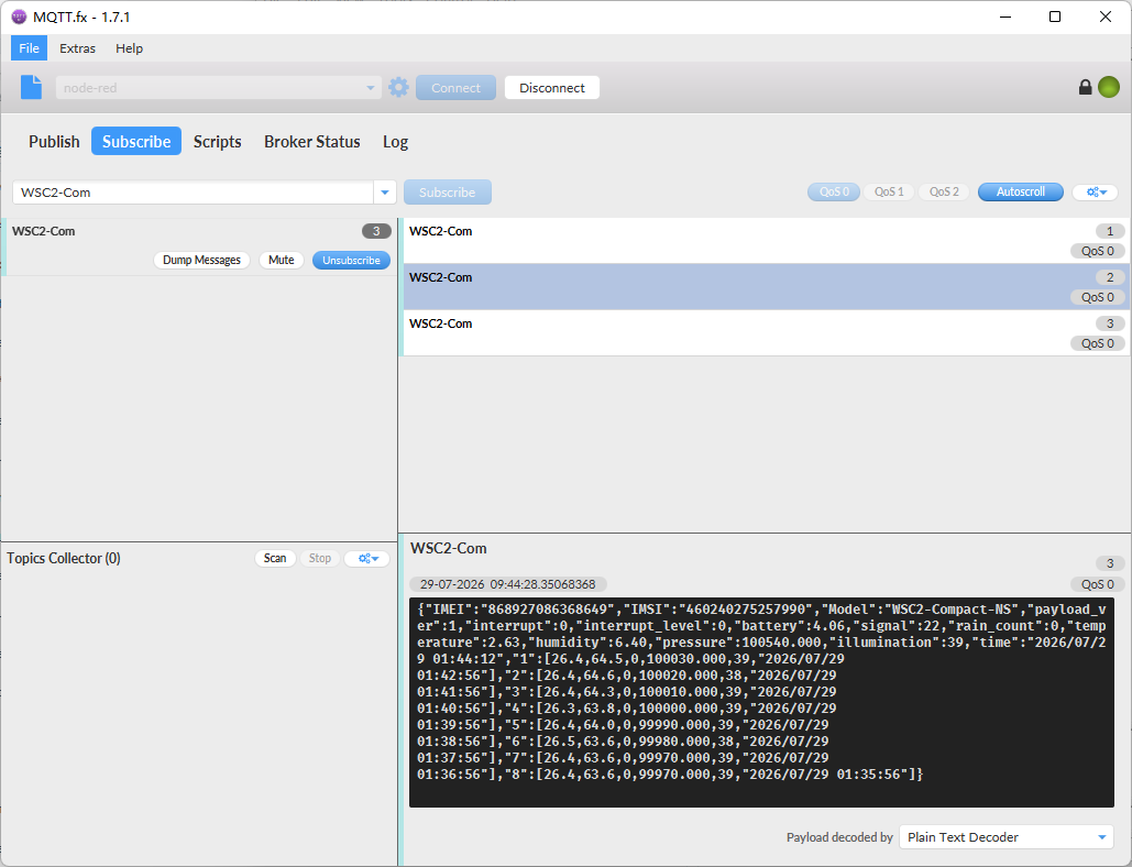
This is the General Json Format. As below:
{
   "IMEI":"868927086368649",
   "IMSI":"460240275257990",
   "Model":"WSC2-Compact-NS",
   "payload_ver":1,
   "interrupt":0,
   "interrupt_level":0,
   "battery":4.16,
   "signal":22,
   "rain_count":0,
   "temperature":2.43,
   "humidity":5.59,
   "pressure":100970.000,
   "illumination":181,
   "time":"2026/07/28 09:05:13",
   "1":[24.4,55.8,0,100960.000,180,"2026/07/28 09:04:01"],
   "2":[24.3,56.0,0,100950.000,181,"2026/07/28 09:03:01"],
   "3":[24.3,56.0,0,100940.000,181,"2026/07/28 09:02:01"],
   "4":[24.5,55.7,0,100940.000,178,"2026/07/28 09:01:01"],
   "5":[24.5,56.2,0,100930.000,176,"2026/07/28 09:00:01"],
   "6":[24.5,55.5,0,100920.000,173,"2026/07/28 08:59:01"],
   "7":[24.6,56.1,0,100930.000,172,"2026/07/28 08:58:01"],
   "8":[24.5,56.0,0,100930.000,173,"2026/07/28 08:57:01"]
}
Example:
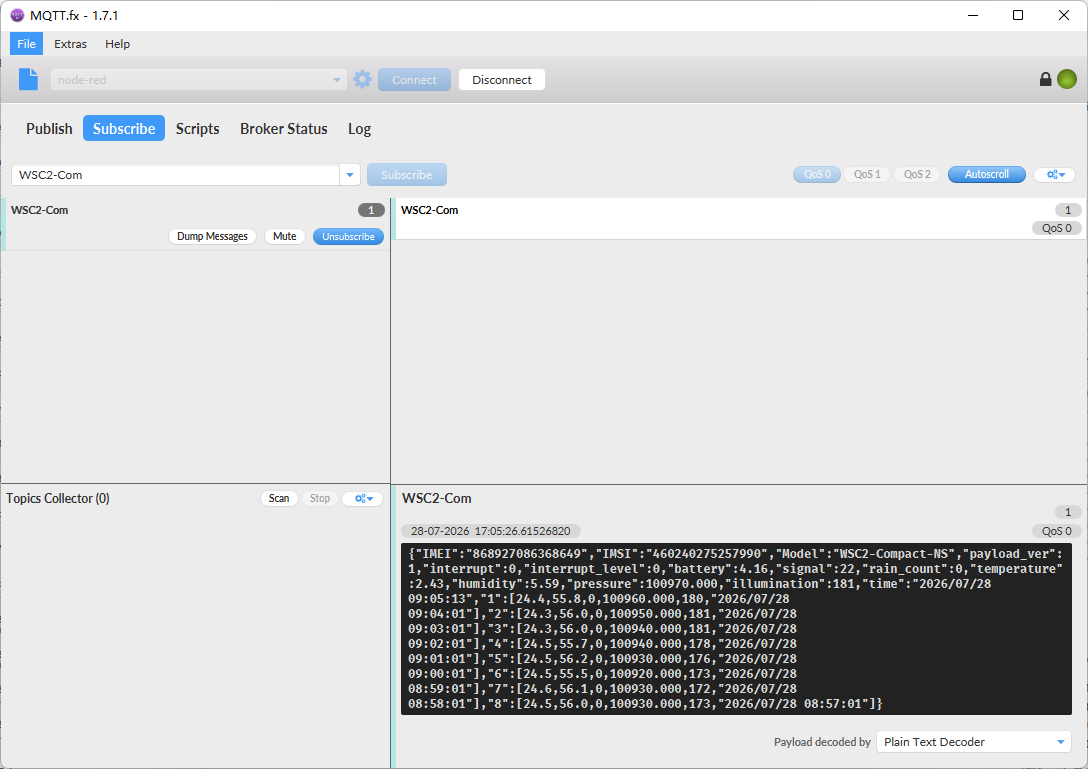
Notice, from above payload:
-
Temperature, Humidity, Interrupt, Interrupt_level, rain_count, pressure, illumination, Battery, Signal & time are the value at uplink time.
-
Json entry 1 ~~ 8 are the last 1 ~~ 8 sampling data as specify by AT+CLOCKLOG=1,65535,15,8 Command. Each entry includes (from left to right): Temperature, Humidity, rain_count, pressure, illumination, Sampling time.
2.2.2 HEX Format Payload (Type=0)
This is the HEX Format. As below:
f868927086368649f4602402752579905e7a103e12010000010000000000f202210000275100b5006a6875d600f2022a00000000000000b427826a68756d00f2022800000000000000b427846a68753100f1022700000000000000b427856a6874f500f1022900000000000000b427876a6874b900f0022c00000000000000b427886a68747d00f0022b00000000000000b427896a68744100f1022d00000000000000b4278a6a68740500f0023400000000000000b4278b6a6873c9

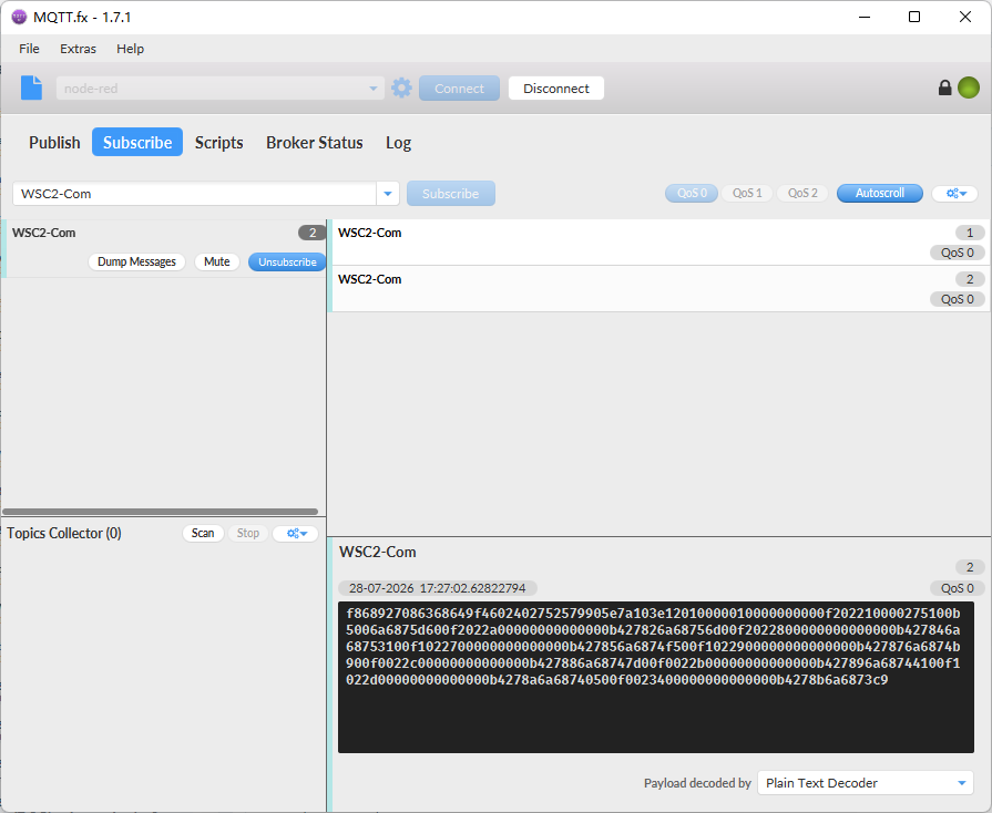
Device ID(f+IMEI): f868927086368649 = 868927086368649
SIM Card ID(f+IMSI): f460240275257990 = 460240275257990
Version:
These bytes include the hardware and software version.
Higher byte: Specify Sensor Model: 0x5e for WSC2-Compact-NS
Lower byte: Specify the software version: 0x7a=122, means firmware version 1.2.2
BAT (Battery Info):
Ex1: 0x103E = 4158mV
Signal Strength:
NB-IoT Network signal Strength.
Ex1: 0x12 = 18
0 -113dBm or less
1 -111dBm
2...30 -109dBm... -53dBm
31 -51dBm or greater
99 Not known or not detectable
MOD:
Ex1: 0x01 = 1
Interrupt:
This data field shows if this packet is generated by interrupt or not.
Example:
If byte[0]&0x01=0x00 : Normal uplink packet.
If byte[0]&0x01=0x01 : Interrupt Uplink Packet.
Interrupt_level:
This byte shows whether the interrupt is triggered by a high or low level.
Ex1: 0x00 Interrupt triggered by falling edge (low level)
Ex2: 0x01 Interrupt triggered by rising edge (high level)
Payload_version:
The payload version number is used to parse different decodes.
count:
When using count mode, GPIO_EXTI will accumulate counts each time it is triggered.
Example: 0x00000064(H)= 100(D), So the count value is 100.
Temperature:
If payload is: 00f2H: (00f2 & 8000 == 0), temp = 00f2H /10 = 24.2 degree
If payload is: FF3FH : (FF3F & 8000 == 1) , temp = (FF3FH - 65536)/10 = -19.3 degrees.
(FF3F & 8000: Judge whether the highest bit is 1, when the highest bit is 1, it is negative)
Humidity:
Read:0221(H)=545(D) Value: 545 / 10=54.5, So 54.5%
Pressure:
0x(0x00002751) = 10065 Value: 10065/10 = 1006.5 hPa
illumination:
Example:
0x(00B5) = 181 Lux
i_flag:
Ex1: 0x00>>5&0x01=0x00 : Normal uplink packet.
Ex2: 0x01>>5&0x01=0x01 : Interrupt Uplink Packet.
TimeStamp:
Unit TimeStamp Example: 6a6875d6(H) = 1785230806(D)
Put the decimal value into this link(Epoch Converter) to get the time.
2.2.3 HEX Format Payload (Type=0)(AT+WSS=1,1,1)
One wind speed sensor
Two soil sensor
- Note on Soil Sensors: The WSC2-Compact-NS can only recognize soil sensors with addresses 01 and 02. When using two soil sensors simultaneously, they must be configured with different addresses (one must be 01 and the other 02).
After enabling the corresponding sensor data readings using the AT+WSS command based on actual requirements.
Example:
AT+WSS=1,1,1 enables all available sensors (default is AT+WSS=0,0,0).
f868927086368649f4602402752579905e7a0ff0110100000100000000010a02a200002741002507000000000000000000000000000000000000000000000000000000006a69508c010902a6000000000000002627076a69500a010902ae000000000000002627076a694fce010a02b3000000000000002627086a694f92010902b7000000000000002627096a694f56010a02bd000000000000002527096a694f1a010902bf0000000000000025270a6a694ede010902c3000000000000002527096a694ea2010a02cd000000000000002527096a694e66

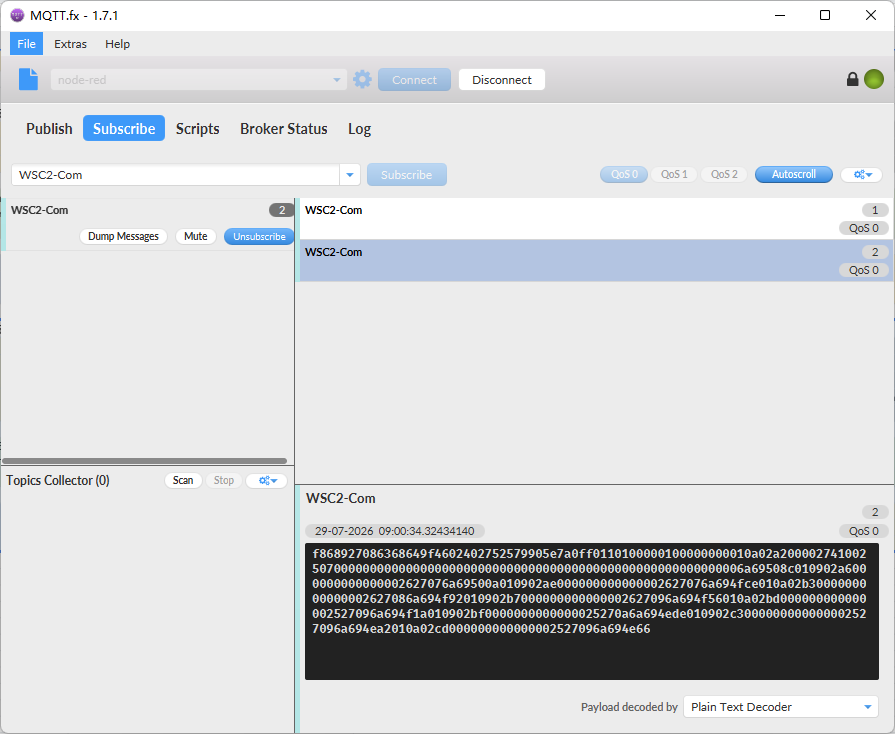
Device ID(f+IMEI): f869181074641067 = 869181074641067
SIM Card ID(f+IMSI): f460240275257991 = 460240275257991
Version:
These bytes include the hardware and software version.
Higher byte: Specify Sensor Model: 0x7e for WSC2-Compact-NS
Lower byte: Specify the software version: 0x7a=122, means firmware version 1.2.2
BAT (Battery Info):
Ex1: 0x0ff0 = 4080mV
Signal Strength:
NB-IoT Network signal Strength.
Ex1: 0x11 = 17
0 -113dBm or less
1 -111dBm
2...30 -109dBm... -53dBm
31 -51dBm or greater
99 Not known or not detectable
MOD:
Ex1: 0x01 = 1
Interrupt:
This data field shows if this packet is generated by interrupt or not.
Example:
If byte[0]&0x01=0x00 : Normal uplink packet.
If byte[0]&0x01=0x01 : Interrupt Uplink Packet.
Interrupt_level:
This byte shows whether the interrupt is triggered by a high or low level.
Ex1: 0x00 Interrupt triggered by falling edge (low level)
Ex2: 0x01 Interrupt triggered by rising edge (high level)
Payload_version:
The payload version number is used to parse different decodes.
count:
When using count mode, PB15 will accumulate counts each time it is triggered.
Example: 0x00000064(H)= 100(D), So the count value is 100.
Temperature:
If payload is: 010aH: (010a & 8000 == 0), temp = 010aH /10 = 26.6 degree
If payload is: FF3FH : (FF3F & 8000 == 1) , temp = (FF3FH - 65536)/10 = -19.3 degrees.
(FF3F & 8000: Judge whether the highest bit is 1, when the highest bit is 1, it is negative)
Humidity:
Read:02a2(H) = 674(D) Value: 674 / 10 = 67.4, So 67.4%
Pressure:
0x(0x00002741) = 10049 Value: 10049/10 = 1004.9 hPa
illumination:
Example:
0x(0025) = 37 Lux
i_flag:
Ex1: 0x00>>5&0x01=0x00 : Normal uplink packet.
Ex2: 0x01>>5&0x01=0x01 : Interrupt Uplink Packet.
(Address 1) water_SOIL:
Get the moisture content of the soil. The value range of the register is 0-10000(Decimal), divide this value by 100 to get the percentage of moisture in the soil.
For example, if the data you get from the register is 0x05 0xDC, the moisture content in the soil is 05DC(H) = 1500(D) /100 = 15%.
(Address 1) conduct_SOIL:
Obtain soluble salt concentration in soil or soluble ion concentration in liquid fertilizer or planting medium. The value range of the register is 0 - 20000(Decimal)( Can be greater than 20000).
For example, if the data you get from the register is 0x00 0xC8, the soil conductivity is 00C8(H) = 200(D) = 200 uS/cm.
Generally, the EC value of irrigation water is less than 800uS / cm.
(Address 1) temp_SOIL:
Get the temperature in the soil. The value range of the register is -4000 - +800(Decimal), divide this value by 100 to get the temperature in the soil. For example, if the data you get from the register is 0x09 0xEC, the temperature content in the soil is
Example:
If payload is 0105H: ((0x0105 & 0x8000)>>15 === 0),temp = 0105(H)/100 = 2.61 °C
If payload is FF7EH: ((FF7E & 0x8000)>>15 ===1),temp = (FF7E(H)-FFFF(H))/100 = -1.29 °C
(Address 2) water_SOIL:
Get the moisture content of the soil. The value range of the register is 0-10000(Decimal), divide this value by 100 to get the percentage of moisture in the soil.
For example, if the data you get from the register is 0x05 0xDC, the moisture content in the soil is 05DC(H) = 1500(D) /100 = 15%.
(Address 2) conduct_SOIL:
Obtain soluble salt concentration in soil or soluble ion concentration in liquid fertilizer or planting medium. The value range of the register is 0 - 20000(Decimal)( Can be greater than 20000).
For example, if the data you get from the register is 0x00 0xC8, the soil conductivity is 00C8(H) = 200(D) = 200 uS/cm.
Generally, the EC value of irrigation water is less than 800uS / cm.
(Address 2) temp_SOIL:
Get the temperature in the soil. The value range of the register is -4000 - +800(Decimal), divide this value by 100 to get the temperature in the soil. For example, if the data you get from the register is 0x09 0xEC, the temperature content in the soil is
Example:
If payload is 0105H: ((0x0105 & 0x8000)>>15 == 0),temp = 0105(H)/100 = 2.61 °C
If payload is FF7EH: ((FF7E & 0x8000)>>15 ==1),temp = (FF7E(H)-FFFF(H))/100 = -1.29 °C
wind_speed_max:
If payload is 000FH: wind_speed_max= 000F(H)/10 = 1.5
wind_speed_average:
If payload is 003DH: wind_speed_average= 003D(H)/10 = 6.1
WIND_SPEED:
If payload is 0006H: WIND_SPEED= 0006(H)/10 = 0.6
WIND_LEVEL:
If payload is 0001H: WIND_LEVEL= 0001(H) = 1
WIND_ANGLE:
If payload is 07B1H: WIND_ANGLE= 07B1(H)/10 = 196.9
WIND_DIRECTION:
If payload is 0009H: WIND_DIRECTION= 0009(H) = 9
TimeStamp:
Unit TimeStamp Example: 6a67167d(H) = 1785140861(D)
Put the decimal value into this link(Epoch Converter) to get the time.
3. Configure WSC2-Compact-NS
3.1 Configure Methods
- AT commands via Bluetooth (recommended): BLE Configure Instruction.
- AT commands via UART: UART Connection.
3.2 Serial Access Password
After the Bluetooth or UART connection is successful, use the Serial Access Password to enter the AT command window.
The label on the box of the node will print the initial password: AT+PIN=xxxxxx, and directly use the six-digit password to access the AT instruction window.
-d3c2886eabf20e0364d03ab409bca4ef.png)
If you need to change the password, use AT+PWORD=xxxxxx (6 characters).
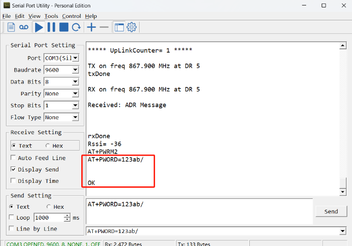
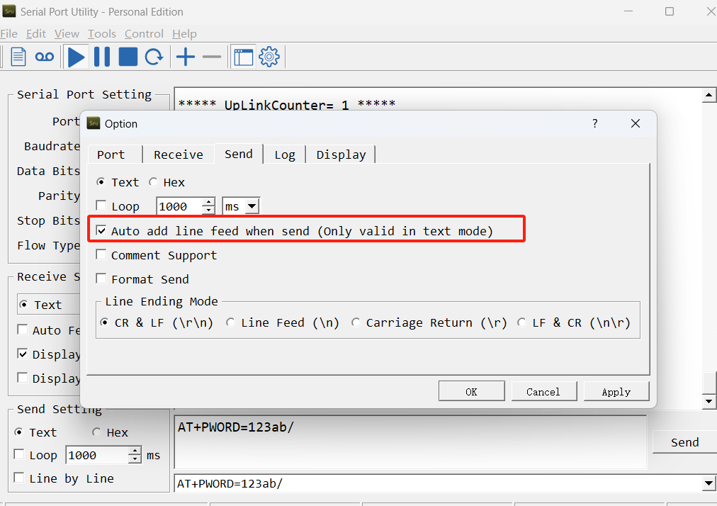
After entering the command, you need to add a line break, and you can also set automatic line breaks in the Bluetooth tool or UART connection tool.
3.3 Test Uplink and Change Update Interval
By default, Sensor will send uplinks every 2 hours.
User can use below commands to change the uplink interval.
AT Command: AT+TDC
Example: AT+TDC=7200 // Set Update Interval to 7200 seconds
Downlink Commands: 0x01
Format: Command Code (0x01) followed by 3 bytes.
Example: 12 hours= 43200 seconds 43200(D)=0xA8C0(H)
3.4 Set the receiving time
Feature: Extend the receiving time
AT Command: AT+RXDL
Example: AT+RXDL=1000 // Set the receiving time delay to 1000ms
Downlink Commands: 0x03
Format: Command Code (0x03) followed by 3 bytes.
Example: Downlink Payload: 03 00 03 E8// AT+RXDL=1000
3.5 Reset
Feature: Trig a reset of the MCU.
AT Command: ATZ
Downlink Commands: 0x04FF
3.6 +5V
Feature: Set extend the time of 5V power.
AT Command: AT+5VT
Example: AT+5VT=2000 // Set extend the time of 5V power to 2000 ms
Downlink Commands: 0x05
Format: Command Code (0x05) followed by 3 bytes.
Example: Downlink Payload: 05 00 07 D0// AT+5VT=2000
3.7 Trigger an uplink by external interrupt
WSC2-Compact-NS has an external trigger interrupt function. Users can use the GPIO_EXTI pin to trigger the upload of data packets.
AT command:
-
AT+INTMOD // Set the trigger interrupt mode
-
AT+INTMOD=0 // Disable Interrupt
-
AT+INTMOD=1 // Trigger by rising and falling edge
-
AT+INTMOD=2 // Trigger by falling edge
-
AT+INTMOD=3 // Trigger by rising edge
Downlink Commands: 0x06
Format: Command Code (0x06) followed by 3 bytes.
Example1: Downlink Payload: 06 00 00 01 // AT+INTMOD=1
Example2: Downlink Payload: 06 00 00 03 // AT+INTMOD=3
3.8 Set the QoS level
This command is used to set the QoS level of MQTT.
AT command:
- AT+MQOS=xx // 0~~2
Downlink command: 0x07
Format: Command Code (0x07) followed by 1 byte.
Ex1: Downlink payload: 0x0700 // AT+MQOS=0
Ex2: Downlink payload: 0x0701 // AT+MQOS=1
3.9 Clock Logging and Historical Records
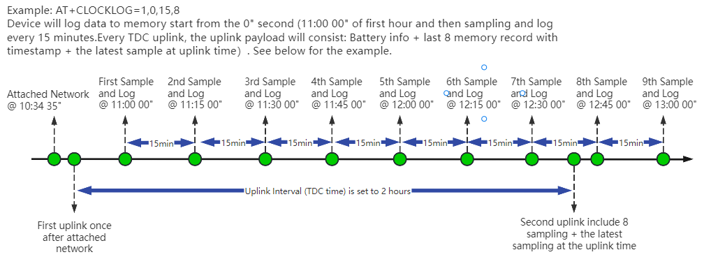
Sometimes when we deploy lots of end nodes in field. We want all sensors sample data at the same time, and upload these data together for analyze. In such case, we can use clock loging feature.
We can use this command to set the start time of data recording and the time interval to meet the requirements of the specific collection time of data.
AT command: AT+CLOCKLOG=a,b,c,d
a: 0: Disable Clock logging. 1: Enable Clock Logging
b: Specify First sampling start second: range (0 ~~ 3599, 65535) // Note: If parameter b is set to 65535, the log period starts after the node accesses the network and sends packets.
c: Specify the sampling interval: range (0 ~~ 255 minutes)
d: How many entries should be uplink on every TDC (max 32)
To disable clock recording, set the following parameters: AT+CLOCKLOG=1,65535,0,0
Example:
AT+CLOCKLOG=1,65535,1,5
After the node sends the first packet, data is recorded to the memory at intervals of 1 minute. For each TDC uplink, the uplink load will include: battery information + the last 5 memory records (payload + timestamp).
Users need to synchronize the server time before configuring this command. If the server time is not synchronized before this command is configured, the command takes effect only after the node is reset.
Downlink command: 0x08
Format: Command Code (0x08) followed by 5 bytes.
Example 1: Downlink Payload: 08 01 FFFF 0F 08 // Set SHT record time: AT+CLOCKLOG=1,65535,15,8
Example 2: Downlink Payload: 08 01 04B0 0F 08 // Set SHT record time: AT+CLOCKLOG=1,1200,15,8
3.10 Set the TLS mode
Refer to this link (MQTT Connection to send data to Tago.io)to use the TLS mode.
AT Command: AT+TLSMOD
Example 1: AT+TLSMOD=0,0 // Disable TLS Mode.
Example 2:
- AT+TLSMOD=1,0 // No authentication
- AT+TLSMOD=1,1 // Perform server authentication
- AT+TLSMOD=1,2 // Perform server and client authentication if requested by the remote server
Downlink command: 0x09
Format: Command Code (0x09) followed by 2 bytes.
Example1: Downlink Payload: 09 00 00 // AT+TLSMOD=0,0
Example2: Downlink Payload: 09 01 02 // AT+TLSMOD=1,2
3.11 Set the search network time
Feature: Get or Set the time to join the network(unit: minutes).
AT Command: AT+CSQTIME
Example: AT+CSQTIME=10 // Set the search time to 10 minutes.
Downlink command: 0x13
Format: Command Code (0x13) followed by 1 byte.
Example: Downlink Payload: 13 0A// AT+CSQTIME=10
3.12 Factory data reset
Two different restore factory Settings configurations.
AT command:
- AT+FDR// Reset Parameters to Factory Default.
- AT+FDR1// Reset parameters to factory default values except for passwords.
3.13 Set CoAP option
This command sets the connection parameters of the COAP.
AT command:
- AT+URI1 // CoAP option name, CoAP option length, "CoAP option value"
- AT+URI2 // CoAP option name, CoAP option length, "CoAP option value"
- AT+URI3 // CoAP option name, CoAP option length, "CoAP option value"
- AT+URI4 // CoAP option name, CoAP option length, "CoAP option value"
Example:
- AT+URI1=11,38,"i/faaa241f-af4a-b780-4468-c671bb574858"
3.14 Example Query saved historical records
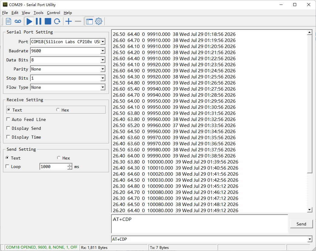
- AT command: AT+CDP
This command can be used to search the saved history, recording up to 32 groups of data, each group of historical data contains a maximum of 100 bytes.
3.15 Uplink log query
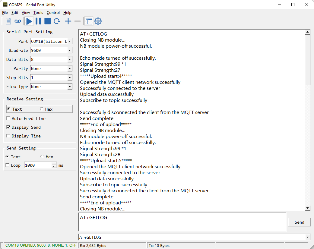
- AT command: AT+GETLOG
This command can be used to query upstream logs of data packets.
3.16 Add External Sensors
Use AT+WSS=a,b,c:
| Parameter | Sensor | Values |
|---|---|---|
| a | Wind speed and direction | 0: disable; 1: enable |
| b | Soil sensor, address 1 | 0: disable; 1: enable |
| c | Soil sensor, address 2 | 0: disable; 1: enable |
Example: AT+WSS=1,1,1 enables all optional sensors. Soil sensors must use addresses 01 and 02.
Downlink Payload: 20 01 01 01 // AT+WSS=1,1,1
3.17 Wind Speed Acquisition Duration
Feature: Get or set the real time wind speed
AT Command: AT+WINDT
| Command Example | Function | Response |
|---|---|---|
| AT+WINDT=? | Get the current sample duration | 20(unit: second) OK Default 20 seconds |
| AT+WINDT=10 | Set the current sample duration (Max: 255s; Min: 0s) | OK Get the current sample duration to 10 seconds |
Downlink Command: 0x21
Format: Command Code (0x21) followed by 1 bytes time value.
If the downlink payload = 2114, this indicates setting the terminal node's wind speed sampling duration to 0x14 = 20 (seconds), with the type code being F1.
- Example 1: Downlink Payload: 2114 // Wind speed sampling duration is set to 20 (seconds)
- Example 2: Downlink Payload: 213C // Wind speed sampling duration is set to 60 (seconds)
3.18 Wiring Method
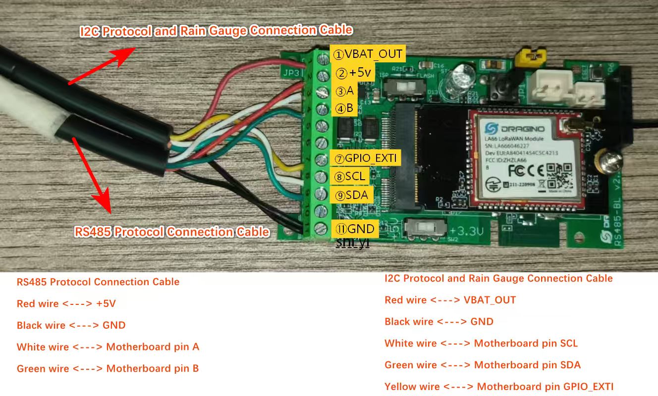
Note: Since the WSC2-Compact-NS uses the I2C protocol as its default sensor communication protocol, but the wind speed and direction sensor, and soil sensor utilize the RS485 protocol, an additional DR-F6C-4 cable must be added to the existing setup.
3.19 Set the downlink debugging mode
Feature: Enable or disable downlink debugging mode. (Since TE platform update, the platform version selection is no longer needed; only downlink debugging can be toggled.)
AT command: AT+DOWNTE
| Command Example | Function/Parameters | Response/Explanation |
|---|---|---|
| AT+DOWNTE=? | Get current Settings | 0,0 (default) OK |
| AT+DOWNTE=0,a | a: Enable/Disable downlink debugging | 0: Disable downlink debugging mode. 1: Enable downlink debugging mode (users can view original downlink messages). |
(Note: The first parameter is fixed to 0 and only the second parameter is configurable.)
Example:
- AT+DOWNTE=0,1 → Enable downlink debugging mode.
- AT+DOWNTE=0,0 → Disable downlink debugging mode.
Downlink Command:
No downlink commands for feature
3.20 Domain name resolution settings
Feature: Set static DNS resolution IP address.
AT command: AT+BKDNS
| Command Example | Function/Parameters | Response/Explanation |
|---|---|---|
| AT+BKDNS=? | Get current Settings | 1,0,NULL (default) OK |
| AT+BKDNS=a,b,c | a: Enable/Disable static DNS resolution. | 0: Disable static DNS resolution 1: Enable static DNS resolution. The ip address will be saved after the domain name is resolved, if the next domain name resolution fails, the last saved ip address will be used. |
| b: Meaningless. | Set to 0. | |
| c: Set the IP address manually. | The format is the same as AT+SERVADDR. If domain name resolution fails, this ip address will be used directly, if domain name resolution succeeds, parameter c will be updated to the successfully resolved IP address. |
Example:
- AT+BKDNS=0,0,NULL //Disable static DNS resolution.
- AT+BKDNS=1,0,NULL // Enable static DNS resolution.
- AT+BKDNS=1,0,3.69.98.183,1883 //Enable static DNS resolution, if domain name resolution succeeds, the node uses the ip address successfully resolved and saves it to parameter c. If the domain name resolution fails, use the manually set ip address: 3.69.98.183 for communication.
Downlink Command:
No downlink commands for feature.
3.21 AT Commands Set
AT+<CMD>? : Help on <CMD>
AT+<CMD> : Run <CMD>
AT+<CMD>=<value> : Set the value
AT+<CMD>=? : Get the value
General Commands:
AT+MODEL : Get module information
ATZ : Trig a reset of the MCU
AT+CFGMOD : Working mode selection
AT+DEUI : Get or set the Device ID
AT+CFG : Print all settings
AT+SERVADDR: Get or Set the Server address
AT+TDC : Get or set the application data transmission interval in s
AT+INTMOD : Get or Set the trigger interrupt mode (0:input,1:falling or rising,2:falling,3:rising)
AT+APN : Get or set the APN
AT+5VT : Get or Set extend the time of 5V power
AT+PRO : Get or Set usage agreement (1:COAP,2:UDP,3:MQTT,4:TCP)
AT+RXDL : Get or Set the receiving time
AT+COUNTMOD : Get or Set the count mode
AT+SETCNT : Get or set the count at present
AT+GETSENSORVALUE : Returns the current sensor measurement
AT+DNSCFG : Get or Set DNS Server
AT+CSQTIME : Get or Set the time to join the network
AT+BKDNS : Get or Set dynamic domain name resolution IP
AT+TLSMOD : Get or Set the TLS mode
AT+SLEEP : Get or Set the sleep mode
AT+GETLOG : Print serial port logs
AT+CLOCKLOG: Get or set SHT record time
AT+DOWNTE: Get or set the conversion between the standard version and 1T version downlinks
AT+WSS: Get or set the wind speed and two soil sensors
AT+WINDT: Get or set the real time wind speed
AT+NTP: Get or set NTP Server
AT+QCOPS: Get or set operator code
AT+LDATA : Get the last upload data
MQTT Management:
AT+MQOS : Set the QoS level of MQTT
AT+CLIENT : Get or Set the MQTT clientID
AT+UNAME : Get or Set the MQTT Username
AT+PWD : Get or Set the MQTT password
AT+PUBTOPIC: Get or set MQTT publishing topic
AT+SUBTOPIC: Get or set MQTT subscription topic
AT+CACERT : Configure CA certificate.
AT+CLICERT : Configure client certificate.
AT+CLIKEY : Configure client private key.
Information:
AT+FDR1 : Reset parameters to factory default values except for passwords
AT+FDR : Reset Parameters to Factory Default
AT+PWORD : Get or set the System password
AT+CDP : Read or Clear cached data
AT+LDATA : Get the last upload data
AT+UPGRADE : OTA upgrade.
COAP Management:
AT+URI1: Get or set CoAP option 1
AT+URI2: Get or set CoAP option 2
AT+URI3: Get or set CoAP option 3
AT+URI4: Get or set CoAP option 4
4. Battery & Power Consumption
WSC2-Compact-NS uses a solar panel and a 3000mAh rechargeable Li-ion battery. Network searches, weak coverage, TLS and continuous wind measurement increase power consumption.
The nominal battery energy is 11.1Wh. With a 0.9W solar panel and 22% estimated charging efficiency, effective charging power is about 0.198W and an ideal full charge takes approximately 56 hours.
5. Firmware Update
User can change device firmware to:
-
Update with new features.
-
Fix bugs.
Firmware and changelog can be downloaded from : Firmware download link
Methods to Update Firmware:
-
(Recommended way) OTA firmware update via BLE: Instruction.
-
Update through UART TTL interface : Instruction.
6. FAQ
6.1 How can I access t BC660K-GL AT Commands?
User can access to BC660K-GL directly and send AT Commands.
6.2 Why is there no LED response when I press the button on the solar panel model?
If the LED does not light up when you press the button, it may be because the battery has entered protection mode.
Solution: To reactivate the battery, simply expose the solar panel to direct sunlight. For more details, please refer to: Battery Protection State (Apply to Solar Panel + Li-ion battery)
7. Order Info
The WSC2-Compact series includes the wireless transmitter only. Sensors must be purchased separately.
Wireless Transmitter: WSC2-Compact-NS
Sensor Options: DR-THP-6P, DR-IL-6P, DR-RG-6P
8. Packing Info
Packing Includes:
- WSC2-Compact-NS NB-IoT weather station transmitter
9. Support
- Support is provided Monday to Friday, 09:00 to 18:00 GMT+8.
- Include the product model, configuration, problem description and reproduction steps when contacting support@dragino.com.