S31B-FE – NB-IoT/LTE-M Temperature & Humidity Sensor
1. Introduction
1.1 What is Temperature & Humidity Sensor
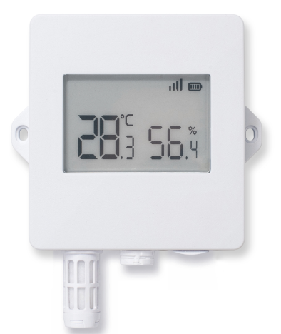
The Dragino S31B-FE is an NB-IoT/LTE-M Temperature and Humidity Sensor for Internet of Things solution. It is used to measure the surrounding environment temperature and relative air humidity precisely, and then upload to IoT server via LTE-M and NB-IoT network.
The temperature & humidity sensor used in S31B-FE is SHT31, which is fully calibrated, linearized, and temperature compensated digital output from Sensirion, it provides a strong reliability and long-term stability. The SHT31 is fixed in a waterproof anti-condensation casing for long term use.
S31B-FE uses the Nordic nrf9151 LTE-M modem, which has much lower power consumption and can work for years. It supports different uplink methods include MQTT, MQTTs, TCP, UDP for different application requirement, and supports uplinks to various IoT Servers.
S31B-FE has a 2.7" E-Ink display which can provide the reading for the environment status.
The device supports configurable temperature and humidity alarms, allowing users to receive instant notifications when readings exceed predefined thresholds.
With built-in BLE configuration and wireless OTA firmware updates, the S31B-FE is simple to set up and maintain. It also supports multiply sampling via one uplink and an optional unique factory calibrate service.
S31B-FE is powered by 8000mAh Li-SOCl2 battery, it is designed for long term use up to 5 years (depending on uplink interval; real-world battery life depends on the use environment, update period and uplink method. Please check related Power Analyze report).
*make sure you have LTE-M or NB-IoT coverage locally.
1.2 Features
- NB-IoT Bands: B1/B2/B3/B4/B5/B8/B12/B13/B17/B19/B20/B25/B26/B28/B65/B66/B85/B106
- CAT-M1 / LTE-M Bands: B1/B2/B3/B4/B5/B8/B12/B13/B18/B19/B20/B25/B26/B28/B66/B85/B106
- Ultra-low power consumption
- 2.7" E-Ink Display
- Measure range 0°C ~ 50°C
- Configurable temperature & humidity alarm
- Multiply Sampling and one uplink
- Uplink via MQTT, MQTTs, TCP, UDP
- Support Bluetooth v5.1 remote configure
- Uplink on periodically
- Downlink to change configure
- 8000mAh Li/SOCl2 Battery
- Nano SIM card slot for NB-IoT SIM
The SHT31 sensing element supports -40 ~ +80°C, but the S31B-FE overall measurement range is 0 ~ 50°C, limited by the 2.7" E-Ink display operating temperature range
1.3 Specification
Common DC Characteristics:
- Supply Voltage: 3.0v ~ 3.6v
- Operating Temperature: 0 ~ 50°C
Temperature Sensor:
- Range: -40 to + 80°C
- Accuracy: ±0.2 @ 0-90 °C
- Resolution: 0.1°C
- Long Term Shift: <0.03 °C/yr
Humidity Sensor:
- Range: 0 ~ 99.9% RH
- Accuracy: ± 2%RH ( 0 ~ 100%RH)
- Resolution: 0.01% RH
- Long Term Shift: <0.25 %RH/yr
NB-IoT Spec:
NB-IoT Module: nRF9151-NGFF
Support Bands:
- B1 @H-FDD: 2100MHz
- B2 @H-FDD: 1900MHz
- B3 @H-FDD: 1800MHz
- B4 @H-FDD: 2100MHz
- B5 @H-FDD: 860MHz
- B8 @H-FDD: 900MHz
- B12 @H-FDD: 720MHz
- B13 @H-FDD: 740MHz
- B17 @H-FDD: 730MHz
- B18 @H-FDD: 870MHz
- B19 @H-FDD: 870MHz
- B20 @H-FDD: 790MHz
- B25 @H-FDD: 1900MHz
- B26 @H-FDD: 876MHz
- B28 @H-FDD: 750MHz
- B65 @H-FDD: 2155MHz
- B66 @H-FDD: 2000MHz
- B85 @H-FDD: 700MHz
Battery:
- Li/SOCI2 un-chargeable battery
- Capacity: 8000mAh
- Self Discharge: <1% / Year @ 25°C
- Max continuously current: 130mA
- Max boost current: 2A, 1 second
Power Consumption:
- STOP Mode: 14uA @ 3.3v
- Max transmit power: 350mA @ 3.3v
1.4 Applications
- Smart Buildings & Home Automation
- Logistics and Supply Chain Management
- Smart Metering
- Smart Agriculture
- Smart Cities
- Smart Factory
1.5 Sleep mode and working mode
Deep Sleep Mode: Sensor doesn't have any NB-IoT/LTE-M activate. This mode is used for storage and shipping to save battery life.
Working Mode: In this mode, Sensor will work as NB-IoT Sensor to Join NB-IoT network and send out sensor data to server. Between each sampling/tx/rx periodically, sensor will be in IDLE mode), in IDLE mode, sensor has the same power consumption as Deep Sleep mode.
1.6 Button & LCD screen
| Behavior on ACT | Function | Action |
|---|---|---|
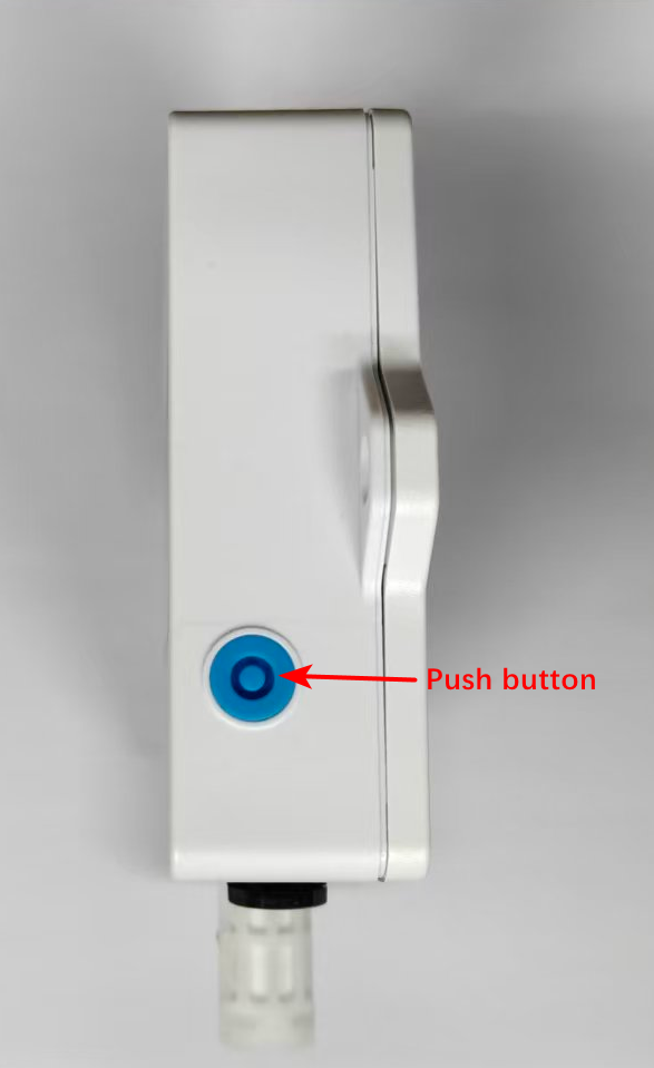
 1~3s 1~3s | Send an uplink | If the sensor is connected to the NB-IoT/LTE-M network, it will send an uplink data packet, and the LCD screen will refresh the displayed temperature and humidity readings. At the same time, the BLE module will be active, allowing users to configure the device via a BLE connection. |
 >3s >3s | Active Device | The LCD screen will refresh once, and the device will enter OTA mode or 12 seconds before beginning to connect to the NB-IoT/LTE-M network. |
 x5 x5 | Deactivate Device | The LCD screen will display “Sleeping.” This indicates that the device is in deep sleep mode. |
Note: When the device is executing a program, the buttons may become invalid. It is best to press the buttons after the device has completed the program execution.
1.7 BLE connection
S31B-FE support BLE remote configure and firmware update.
BLE can be used to configure the parameter of sensor or see the console output from sensor. BLE will be only activate on below case:
- Press button to send an uplink
- Press button to active device.
- Device Power on or reset.
If there is no activity connection on BLE in 60 seconds, sensor will shut down BLE module to enter low power mode.
1.8 Pin Definitions & SIM Direction
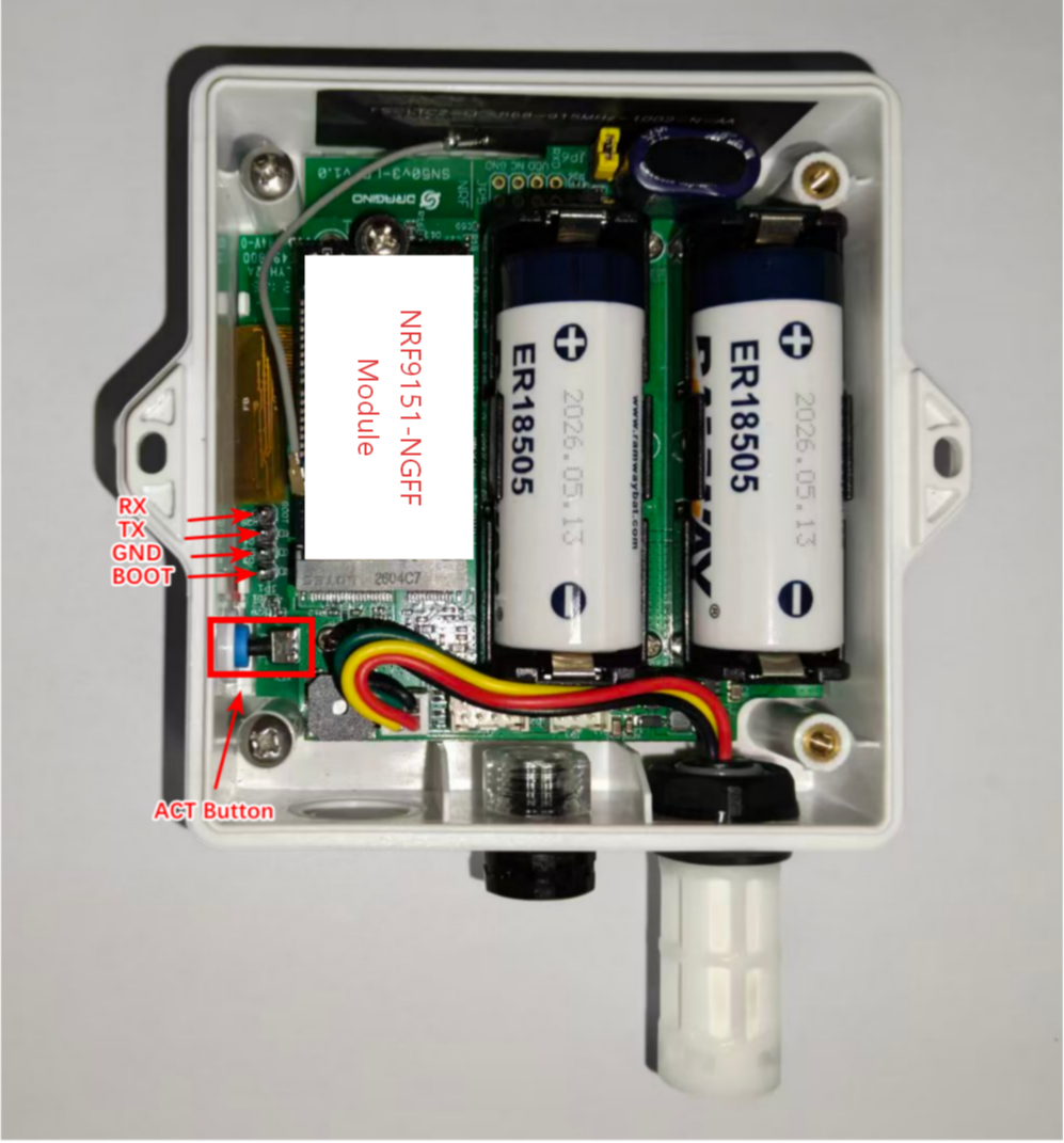
1.8.3 ACT Button
Device function buttons; for specific functions, please refer to: 1.6 Button & LCD screen
1.8.4 SIM Card Direction
See this link. How to insert SIM Card.
2. Use S31B-FE to communicate with IoT Server
2.1 Send data to IoT server via NB-IoT/LTE-M network
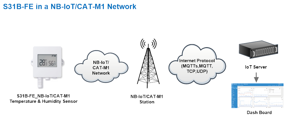
The S31B-FE is equipped with a NB-IoT module, the pre-loaded firmware in S31B-FE will get environment data from sensors and send the value to local NB-IoT network via the NB-IoT module. The NB-IoT network will forward this value to IoT server via the protocol defined by S31B-FE.
Below shows the network structure:
There are two version: -GE and -1T version of S31B-FE.
GE Version: This version doesn't include SIM card or point to any IoT server. User needs to use AT Commands to configure below two steps to set S31B-FE send data to IoT server.
- Install NB-IoT SIM card and configure APN. See instruction of Attach Network.
- Set up sensor to point to IoT Server. See instruction of Configure to Connect Different Servers.
Below shows result of different server as a glance.
| Servers | Dash Board | Comments |
| Node-Red |
| |
| DataCake |
| |
| Tago.IO | ||
| General UDP | Raw Payload. Need Developer to design Dash Board | |
| General MQTT | Raw Payload. Need Developer to design Dash Board | |
| ThingSpeak |
| |
| ThingsBoard |
|
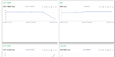
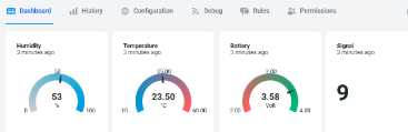
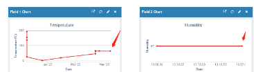
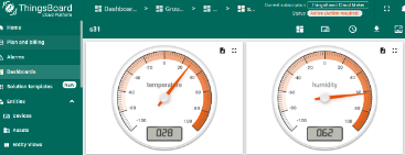
1T Version: This version has 1NCE SIM card pre-installed and configure to send value to ThingsEye. User Just need to select the sensor type in ThingsEye and Activate S31B-FE and user will be able to see data in ThingsEye. See here for ThingsEye Config Instruction.
2.2 Payload Types
S31B-FE supports JSON payloads (Type=0). Use AT+PRO to select the connection protocol:
AT+PRO=2,0// UDP connection with JSON payloadAT+PRO=3,0// MQTT connection with JSON payloadAT+PRO=4,0// TCP connection with JSON payload
Firmware V1.1.5 introduces Clock Logging. The examples below describe the latest JSON payloads for periodic uplinks and uplinks triggered when the configured number of records has been collected.
2.2.1 Periodic Uplinks
Example configuration:
AT+TDC=7200: Send a periodic uplink every 7200 seconds (2 hours). This is the default uplink interval.AT+ATDC=65535,1,8: Start the logging period after the node connects to the network and sends its first packet, sample every 1 minute, and include 8 stored records in each periodic uplink.
Note: The default clock logging configuration is AT+ATDC=65535,15,8. These examples use a 1-minute sampling interval instead of the default 15 minutes.
Each periodic uplink includes device and battery information, the latest sensor readings and status fields, and the latest 8 stored records.
Example payload:
{"IMEI":"355025936334455","IMSI":"460240275256466","Model":"S31B-FE","fcnt":"1","signal":"24","bat":3641,"bat_level":"100%","temperature":25.9,"humidity":49.2,"alarm":"0","status":"0","i_flag":"0","Cell_id":"180520766","Cell_area":"7482","time":"2026-10-20T07:02:06Z","1":["25.9,49.2,0,2026-10-20T06:55:45Z"],"2":["25.8,49.0,0,2026-10-20T06:56:45Z"],"3":["25.8,49.0,0,2026-10-20T06:57:45Z"],"4":["25.8,49.0,0,2026-10-20T06:58:45Z"],"5":["25.8,49.0,0,2026-10-20T06:59:45Z"],"6":["25.8,48.7,0,2026-10-20T07:00:45Z"],"7":["25.8,48.6,0,2026-10-20T07:01:45Z"],"8":["25.8,49.2,0,2026-10-20T07:02:06Z"]}
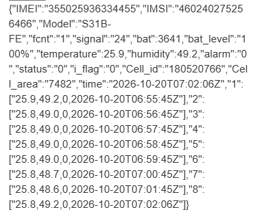
- The top-level
temperatureandhumidityfields contain the latest readings taken at uplink time. - Keys
"1"through"8"contain stored sensor records. Each value is an array containing one comma-separated string in this order: temperature (°C), humidity (%RH), alarm flag, timestamp (UTC). batis the battery voltage in mV, andbat_levelis the battery percentage.- The top-level
timeis the uplink timestamp; each stored record has its own sampling timestamp.
Alarm flag
Alarm flag (alarm): Identifies the packet type.
| Value | Description |
|---|---|
"0" | Normal TDC uplink packet. |
"1" | Uplink packet triggered by a temperature or humidity alarm. |
Temperature alarm status
Temperature alarm status (status): Indicates the temperature alarm state according to the AT+SHTEMP settings.
| Value | Description |
|---|---|
"0" | Temperature alarm disabled (AT+SHTEMP=0,0,0). |
"N1" | Temperature alarm enabled; temperature is within the normal range. |
"L1" | Low-temperature alarm state. |
"H1" | High-temperature alarm state. |
"H2" | Extreme-high-temperature alarm state. |
The two fields serve different purposes: alarm identifies the packet type, while status indicates the temperature alarm state. For example, "alarm":"1","status":"L1" indicates an alarm uplink reporting a low-temperature alarm state.
Note: Humidity alarms do not have a separate alarm status field. A humidity alarm sets alarm to "1", while status continues to indicate the temperature alarm state.
2.2.2 Uplinks After Collecting the Configured Number of Records
Example configuration:
AT+TDC=0: Send an uplink as soon as the configured number of records has been collected, instead of using a fixed uplink interval.AT+ATDC=65535,1,8: Start the logging period after the node connects to the network and sends its first packet, sample every 1 minute, and send an uplink after collecting 8 records.
The node collects and uploads data in batches of 8 records. The default clock logging configuration is AT+ATDC=65535,15,8; the example uses a 1-minute sampling interval.
Example payload:
{"IMEI":"355025936334455","IMSI":"460240275256466","Model":"S31B-FE","fcnt":"3","signal":"27","bat":3614,"bat_level":"97%","Cell_id":"180520766","Cell_area":"7482","time":"2026-10-20T07:15:49Z","1":["25.7,47.9,0,2026-10-20T07:09:45Z"],"2":["25.7,48.2,0,2026-10-20T07:10:45Z"],"3":["25.6,48.1,0,2026-10-20T07:11:45Z"],"4":["25.6,48.5,0,2026-10-20T07:12:45Z"],"5":["25.6,49.0,0,2026-10-20T07:13:45Z"],"6":["25.6,48.2,0,2026-10-20T07:14:23Z"],"7":["25.5,47.7,0,2026-10-20T07:14:45Z"],"8":["25.5,47.8,0,2026-10-20T07:15:45Z"]}
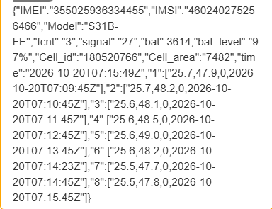
The numbered records use the same format as in Section 2.2.1. In this mode, the payload contains the 8 collected records without the additional top-level temperature, humidity, alarm, status, and i_flag fields. Device information, battery information, cell information, and the uplink timestamp are still included.
Do not use AT+TDC=0 together with AT+ATDC=65535,0,0 (disable clock logging). Otherwise, the node will upload invalid payloads containing no sensor data.
3. Configure S31B-FE
3.1 Configure Methods
S31B-FE supports below configure method:
-
AT Command via Bluetooth Connection (Recommended): BLE Configure Instruction.
-
AT Command via UART Connection : See UART Connection.
3.2 Serial Access Password
Before sending commands, you must first enable the module's serial port functionality; by default, the device's serial port is disabled.
After the Bluetooth or UART connection is successful, use the Serial Access Password to enter the AT command window.
The label on the box of the node will print the initial password: AT+PIN=xxxxxx, and directly use the six-digit password to access the AT instruction window.
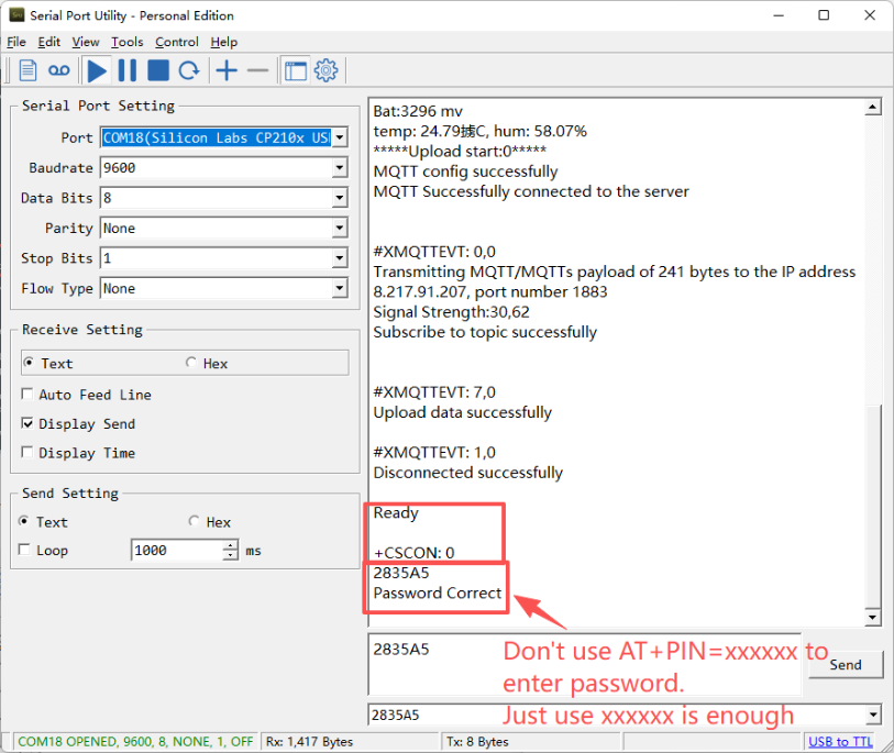
If you need to change the password, use **AT+PWORD=**xxxxxx (6 characters), -FE nodes only support lowercase letters.
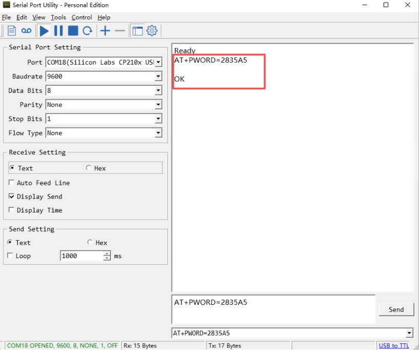
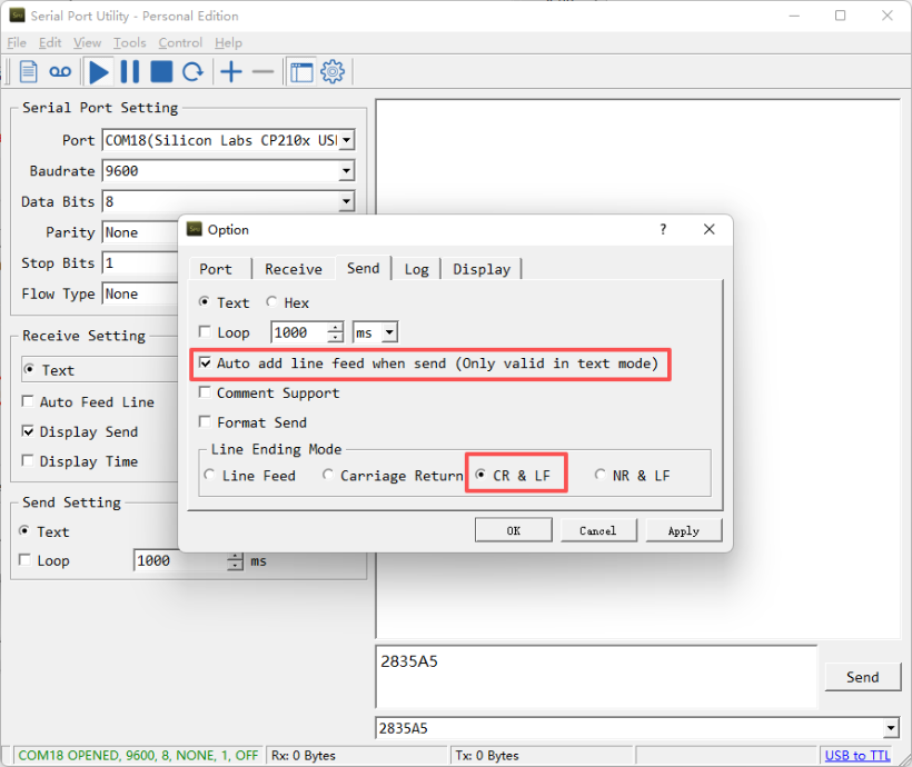
Note: After entering the command, you need to add a line break, and you can also set automatic line breaks in the Bluetooth tool or UART connection tool.
3.3 AT Commands Set
AT+
AT+
AT+
AT+
General Commands:
AT+MODEL : Get module information
AT+CFGMOD : Working mode selection
AT+DEUI : Get or set the Device ID
AT+CFG : Print all settings
AT+SERVADDR: Get or Set the Server address
AT+TDC : Get or set the application data transmission interval in s
AT+INTMOD : Get or Set the trigger interrupt mode (0:input,1:falling or rising,2:falling,3:rising)
AT+APN : Get or set the APN
AT+5VT : Get or Set extend the time of 5V power
AT+PRO : Get or Set usage agreement (2:UDP,3:MQTT,4:TCP)
AT+RXDL : Get or Set the receiving time
AT+EXT : Get or Set Count value
AT+SHTEMP:Get or Set alarm of shtemp
AT+SHHUM:Get or Set alarm of shthum
AT+GETSENSORVALUE : Returns the current sensor measurement
AT+DNSCFG : Get or Set DNS Server
AT+SLEEP : Get or Set the sleep mode
AT+IOTMOD: Configure Network Category to be Searched for under LTE RAT
MQTT Management:
AT+CLIENT : Get or Set the MQTT clientID
AT+UNAME : Get or Set the MQTT Username
AT+PWD : Get or Set the MQTT password
AT+PUBTOPIC: Get or set MQTT publishing topic
AT+SUBTOPIC: Get or set MQTT subscription topic
AT+MQOS : Set the QoS level of MQTT
AT+TLSMOD : Get or Set the TLS mode
Information:
AT+FDR1 : Reset parameters to factory default values except for passwords
AT+FDR : Reset Parameters to Factory Default
AT+PWORD : Get or set the System password
AT+LDATA : Get the last upload data
AT+CDP : Read or Clear cached data
AT+PDTA: Print the sector data from start page to stop page
AT+PLDTA: Print the last few sets of data
AT+CLRDTA: Clear the storage, record position back to 1st
AT+GETLOG : Print serial port logs
ATZ : Trig a reset of the MCU
AT+UDPMOD: Get or set UDP working mode
AT+REDPT: Get or Set the function of reconnecting the network to send data
AT+QCOPS: Get or set operator code
AT+DEBUG: Get or Set the debug mode
3.4 Test Uplink and Change Update Interval
Feature: Set the node's uplink interval in seconds. The default is 7200 seconds (2 hours).
AT Command: AT+TDC
| Command Example | Function |
|---|---|
AT+TDC=? | Show the current uplink interval. |
AT+TDC=600 | Set the uplink interval to 600 seconds (10 minutes). |
AT+TDC=0 | Send an uplink as soon as the number of records specified by parameter c of AT+ATDC has been collected, instead of using a fixed interval. Available in V1.1.5 and later. |
For periodic uplinks, use AT+TDC=<seconds> with a non-zero interval.
Do not use AT+TDC=0 together with AT+ATDC=65535,0,0 (disable clock logging). Otherwise, the node will upload invalid payloads containing no sensor data.
Downlink Command: 0x01
Format: Command code 0x01 followed by the interval in seconds, encoded as 3 bytes.
01000258// Same asAT+TDC=600: send a periodic uplink every 10 minutes.01000000// Same asAT+TDC=0: send an uplink after collecting the configured number of records.
Note: Enter the downlink payload without spaces between bytes.
Users can also press the ACT button for 1–3 seconds to trigger an uplink.
3.5 Set the receiving time
Feature: Extend the receiving time
AT Command: AT+RXDL
Example: AT+RXDL=1000 // Set the receiving time delay to 1000ms
Downlink Commands: 0x03
Format: Command Code (0x03) followed by 3 bytes.
Example: Downlink Payload: 03 00 03 E8 // AT+RXDL=1000
3.6 Reset
Feature: Trig a reset of the MCU.
AT Command: ATZDownlink Commands: 0x04FF
3.7 +5V
Feature: Set extend the time of 5V power.
AT Command: AT+5VT
Example: AT+5VT=2000 // Set extend the time of 5V power to 2000 ms
Downlink Commands: 0x05
Format: Command Code (0x05) followed by 3 bytes.
Example: Downlink Payload: 05 00 07 D0 // AT+5VT=2000
3.8 Trigger an uplink by external interrupt
S31B-FE has an external trigger interrupt function. Users can use the PA15 pin to trigger the upload of data packets.
AT command:
- AT+INTMOD // Set the trigger interrupt mode
- AT+INTMOD=0 // Disable Interrupt
- AT+INTMOD=1 // Trigger by rising and falling edge
- AT+INTMOD=2 // Trigger by falling edge
- AT+INTMOD=3 // Trigger by rising edge
Downlink Commands: 0x06
Format: Command Code (0x06) followed by 3 bytes.
Example1: Downlink Payload: 06 00 00 01 // AT+INTMOD=1
Example2: Downlink Payload: 06 00 00 03 // AT+INTMOD=3
3.9 Set the QoS level
This command is used to set the QoS level of MQTT.
AT command:
- AT+MQOS=xx // 0~2
Downlink command: 0x07
Format: Command Code (0x07) followed by 1 byte.
Ex1: Downlink payload: 0x0700 // AT+MQOS=0
Ex2: Downlink payload: 0x0701 // AT+MQOS=1
3.11 Set the TLS mode
Refer to this link (MQTT Connection to send data to Tago.io)to use the TLS mode.
AT Command: AT+TLSMOD
Example 1: AT+TLSMOD=0,0 // Disable TLS Mode.
Example 2:
- AT+TLSMOD=1,0 // No authentication
- AT+TLSMOD=1,1 // Perform server authentication
- AT+TLSMOD=1,2 // Perform server and client authentication if requested by the remote server
Downlink command: 0x09
Format: Command Code (0x09) followed by 2 bytes.
Example1: Downlink Payload: 09 00 00 // AT+TLSMOD=0,0
Example2: Downlink Payload: 09 01 02 // AT+TLSMOD=1,2
3.12 Set the IPv4 or IPv6
This command is used to set IP version.
AT command:
- AT+IPTYPE=1 // IPv4
- AT+IPTYPE=2 // IPv6
3.13 Configure Network Category to be Searched for under LTE RAT.
AT command: AT+IOTMOD=a,b,c
a: 0: Disenable eMTC; 1: Enable eMTC
b: 0: Disenable NB-IoT ; 1. Enable NB-IOT
c:Priority: If two network categories are enabled simultaneously, the device will give priority to the configured category.
Ext1: AT+IOTMOD=1,1,2 ---->Indicates that both eMTC and NB-IoT are enabled, with priority given to the NB-IoT network type.
3.14 Factory data reset
Two different restore factory Settings configurations.
AT command:
- AT+FDR // Reset Parameters to Factory Default.
- AT+FDR1 // Reset parameters to factory default values except for passwords.
3.15 Print last few data entries
Feature: Print the last few data entries
AT command: AT+PLDTA
| Command Example | 4 bytes |
|---|---|
| AT+PLDTA=5 Print last 5 entries | AT+PLDTA=5 0001 2026/4/27 06:41:02 3657 temp=24.6 hum=59.1 alarm:false 0002 2026/4/27 07:01:03 3645 temp=24.8 hum=57.8 alarm:false 0003 2026/4/27 07:21:03 3653 temp=24.6 hum=59.9 alarm:false 0004 2026/4/27 07:29:47 3296 temp=24.7 hum=58.0 alarm:false 0005 2026/4/27 07:49:47 3637 temp=24.6 hum=57.3 alarm:false OK |
Downlink Command:
No downlink commands for feature
3.16 Print data entries base on page
Feature: Print the sector data from start page to stop page.
AT command: AT+PDTA
| Command Example | 4 bytes |
|---|---|
| AT+PDTA=1,1 Print page 1 to 1 | E8000 2026/4/24 09:20:17 3335 temp=27.2 hum=59.8 alarm:false E8010 2026/4/24 09:21:03 3339 temp=27.3 hum=60.0 alarm:false E8020 2026/4/24 09:22:56 3359 temp=27.0 hum=60.4 alarm:false E8030 2026/4/24 09:58:00 3363 temp=25.6 hum=63.0 alarm:false E8040 2026/4/25 00:35:55 3226 temp=24.5 hum=64.0 alarm:false E8050 2026/4/25 00:44:32 3324 temp=25.1 hum=63.8 alarm:false E8060 2026/4/25 01:04:32 3676 temp=25.1 hum=64.7 alarm:false E8070 2026/4/25 01:24:32 3680 temp=25.1 hum=62.1 alarm:false OK |
Downlink Command:
No downlink commands for feature
3.17 Clear Flash Record
Feature: Clear flash storage for data log feature.
AT command: AT+CLRDTA
| Command Example | Function | Response |
|---|---|---|
| AT+CLRDTA | Clear date record | Stop Tx events,Please wait for the erase to complete Clear all stored sensor data... Start Tx events OK |
Downlink Command: 0x32
- Example: 0x32 00 // Same as AT+CLRDTA
3.18 Working mode selection
Feature: Set interrupt mode or count mode (PA15 pin).
AT command: AT+CFGMOD
| Command Example | Function |
|---|---|
| AT+CFGMOD=1 | Interrupt mode (default mode) |
| AT+CFGMOD=2 | count mode |
Downlink Command: 0x02
- Downlink command: 02 01 // Equal to AT+CFGMOD=1
- Downlink command: 02 02 // Equal to AT+CFGMOD=2
3.19 Debug mode
Feature: Since the serial communication feature of the NRF9151 module requires activation, this command is intended for users who need to use the serial port for extended periods of time.
AT command: AT+DEBUG
| Command Example | Function |
|---|---|
| AT+DEBUG=1 | Enter debugging mode |
| AT+DEBUG=0 | Exit debugging mode,Serial port function disabled |
Note: 1. This feature remains active for only 5 minutes; it will automatically turn off after 5 minutes. 2. Keeping the serial port open continuously increases power consumption in sleep mode; the continuous current is 900 μA.
3.20 Clock Logging and Alarm Sampling Interval
Available in firmware v1.1.5 and later.
In earlier firmware versions, AT+ATDC only set the minimum interval between two alarm uplinks. Starting from firmware v1.1.5, this command configures the first sampling time, the sampling interval, and the number of stored records included in each periodic uplink.
This feature allows the node to sample and store sensor data at a scheduled start time and a specified sampling interval, then upload multiple stored records in a single periodic uplink. The node also checks the configured alarm thresholds at each sampling time.
AT Command: AT+ATDC=a,b,c
| Parameter | Description |
|---|---|
| a | First sampling start second within each hour. Range: 0–3599, or 65535. If a=65535, the logging period starts after the node connects to the network and sends its first packet. |
| b | Sampling interval, in minutes. Range: 0–255. To disable clock logging, use AT+ATDC=65535,0,0. |
| c | Number of stored historical records included in each periodic TDC uplink. Maximum: 32. This count does not include the latest sample taken at uplink time. |
Downlink Command: 0x16
Format: 16 aa aa bb cc — parameter a uses 2 bytes; parameters b and c use 1 byte each.
Example:
16FFFF0F08// Same asAT+ATDC=65535,15,8.1600000108// Same asAT+ATDC=0,1,8.
- Default configuration: AT+ATDC=65535,15,8
- The sampling interval is set by parameter b, while the periodic uplink interval is set by
AT+TDC. - Time synchronization: Synchronize the node's time with the server before configuring this command. If the server time has not been synchronized before configuration, the command takes effect only after the node is reset.
- Restart after re-enabling clock logging: After disabling clock logging with
AT+ATDC=65535,0,0, restart the node after re-enabling it withAT+ATDC. Otherwise, the node will not sample data correctly at the configured interval.
Each periodic TDC uplink includes battery information + the latest c stored historical records (sensor data and timestamps) + the latest sample taken at uplink time.
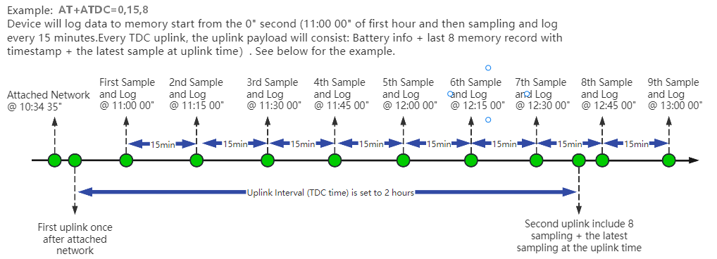
- Example 1: Sample every 15 minutes starting on the hour
AT+ATDC=0,15,8
The node starts logging at the 0th second of the hour and then records sensor data every 15 minutes. Each periodic TDC uplink includes battery information + the latest 8 stored historical records and their timestamps + the latest sample taken at uplink time.
In the example below, the node connects to the network at 10:34:35 and sends its first uplink. It starts logging at 11:00:00, followed by samples at 11:15:00, 11:30:00, and so on. With AT+TDC=7200 (2 hours), the next periodic uplink includes the latest 8 stored historical records and the latest sample taken at uplink time, together with battery information.
- Example 2: Start logging after the first uplink
AT+ATDC=65535,1,8
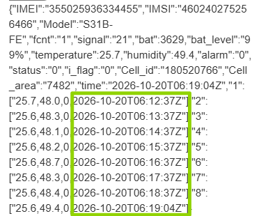
After the node connects to the network and sends its first packet, the logging period starts. The node records sensor data every 1 minute, without waiting for a specified second within the hour. Each periodic TDC uplink includes battery information + the latest 8 stored historical records and their timestamps + the latest sample taken at uplink time.
- Disable clock logging:
AT+ATDC=65535,0,0
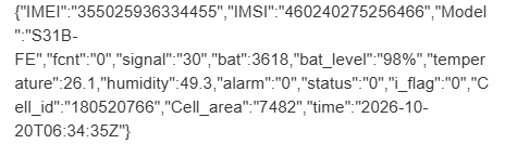
Do not use AT+TDC=0 (uplink immediately after the configured number of records has been collected) together with AT+ATDC=65535,0,0 (disable clock logging). Otherwise, the device will upload invalid payloads containing no sensor data.
AT+ATDC=65535,0,0 & AT+TDC=0:

- Alarm behavior:
When an alarm threshold is configured, the node checks the sensor readings at each sampling time determined by parameter b:
- If a reading meets a configured alarm condition, the node sends an alarm uplink.
- At the next sampling time, the node checks the readings again. If an alarm condition is still met, it sends another alarm uplink. If no alarm condition is met, it does not send an alarm uplink for that sample.
For example, with AT+ATDC=65535,15,8, the node checks for alarm conditions every 15 minute. If a reading exceeds a configured upper alarm threshold, the node sends an alarm uplink. If the next reading returns to the normal range, no alarm uplink is sent for that sample.
Note: In firmware v1.1.5 and later, AT+ATDC is no longer simply a minimum alarm interval setting. Alarm uplinks are triggered by the readings obtained at each configured sampling time. A shorter sampling interval increases sampling frequency and may increase alarm uplink frequency, resulting in higher power consumption.
3.21 Display screen control
Feature: Enable or disable the sensor data display on the screen.
AT Command: AT+DISPLAY
AT+DISPLAY : Get or set the display screen off or on.
| Command Example | Function |
|---|---|
| AT+DISPLAY=? | Get the current display setting. |
| AT+DISPLAY=0 | Enable the sensor data display (default). |
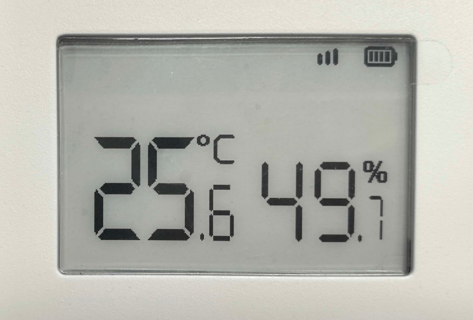
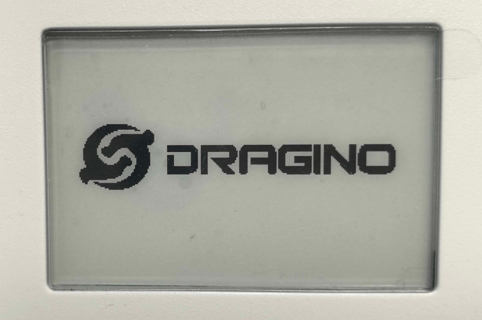
| AT+DISPLAY=1 | Disable the sensor data display. Show only the Dragino logo. |
When AT+DISPLAY=0, the screen updates and displays the latest sensor data after the device joins the network and sends an uplink packet.
When AT+DISPLAY=1, the screen shows only the Dragino logo.
Downlink Command: 0x19
- Example: 0x1900 // Same as AT+DISPLAY=0
- Example: 0x1901 // Same as AT+DISPLAY=1
3.22 Temperature display mode
Feature: Set the temperature unit displayed on the screen.
AT Command: AT+TEMPMODE
AT+TEMPMODE : Get or set the temperature display mode.
| Command Example | Function |
|---|---|
| AT+TEMPMODE=? | Get the current temperature display mode. |
| AT+TEMPMODE=0 | Display the latest temperature reading in Celsius (°C). |
| AT+TEMPMODE=1 | Display the latest temperature reading in Fahrenheit (°F). |
Downlink Command: 0x18
- Example: 0x1800 // Same as AT+TEMPMODE=0
- Example: 0x1801 // Same as AT+TEMPMODE=1
3.23 Humidity Alarm Function
Feature: Get or set the humidity alarm thresholds.
AT Command: AT+SHHUM=min,max
| Parameter | Description |
|---|---|
| min | Lower humidity threshold (%RH). 0 means the lower threshold is not set. |
| max | Upper humidity threshold (%RH). 0 means the upper threshold is not set. |
- If only min is set, a reading below min triggers an alarm.
- If only max is set, a reading above max triggers an alarm.
- If both are set, a reading below min or above max triggers an alarm.
| Command Example | Function |
|---|---|
AT+SHHUM=? | Show the current humidity alarm thresholds. |
AT+SHHUM=70,0 | Trigger an alarm when humidity is below 70%RH. |
AT+SHHUM=0,80 | Trigger an alarm when humidity is above 80%RH. |
AT+SHHUM=50,80 | Trigger an alarm when humidity is below 50%RH or above 80%RH. |
AT+SHHUM=0,0 | Disable the humidity alarm. |
Downlink Command: 0x17
Format: 17 xx xx — min followed by max, 1 byte each.
Example: 173250 // Same as AT+SHHUM=50,80.
The node checks the thresholds at each sampling time configured by AT+ATDC and sends an alarm uplink when an alarm condition is met.
3.24 Temperature Alarm Function
Feature: Get or set three temperature thresholds for low-temperature, high-temperature, and extreme-high-temperature alarms.
AT Command: AT+SHTEMP=L1,H1,H2
| Parameter | Description |
|---|---|
| L1 | Low-temperature threshold (°C). A reading below this value triggers a low-temperature alarm. |
| H1 | High-temperature threshold (°C). A reading above this value triggers a high-temperature alarm. |
| H2 | Extreme-high-temperature threshold (°C). A reading above this value triggers an extreme-high-temperature alarm. |
Requirement: When the temperature alarm is enabled, the thresholds must satisfy L1 < H1 < H2. Set AT+SHTEMP=0,0,0 to disable the temperature alarm.
The normal temperature range is L1 to H1, inclusive. Within this range, no temperature alarm is triggered, and any existing temperature alarm is automatically cleared.
| Command Example | Function |
|---|---|
AT+SHTEMP=? | Show the current three temperature thresholds. |
AT+SHTEMP=10,30,40 | Set the low, high, and extreme-high thresholds to 10°C, 30°C, and 40°C, respectively. |
AT+SHTEMP=0,0,0 | Disable the temperature alarm. |
Downlink Command: 0x08
Format: 08 xx xx xx — L1, H1, and H2, 1 byte each.
Example: 080A1E28 // Same as AT+SHTEMP=10,30,40.
For this example:
- Below 10°C: Low-temperature alarm.
- 10°C to 30°C, inclusive: Normal range; any existing temperature alarm is cleared.
- Above 30°C and up to 40°C: High-temperature alarm.
- Above 40°C: Extreme-high-temperature alarm.
The node checks the thresholds at each sampling time configured by AT+ATDC and sends an alarm uplink when an alarm condition is met.
3.23 Humidity Alarm Function
Feature: Get or set the humidity alarm thresholds.
AT Command: AT+SHHUM=min,max
| Parameter | Description |
|---|---|
| min | Lower humidity threshold (%RH). 0 means the lower threshold is not set. |
| max | Upper humidity threshold (%RH). 0 means the upper threshold is not set. |
- If only min is set, a reading below min triggers an alarm.
- If only max is set, a reading above max triggers an alarm.
- If both are set, a reading below min or above max triggers an alarm.
| Command Example | Function |
|---|---|
AT+SHHUM=? | Show the current humidity alarm thresholds. |
AT+SHHUM=70,0 | Trigger an alarm when humidity is below 70%RH. |
AT+SHHUM=0,80 | Trigger an alarm when humidity is above 80%RH. |
AT+SHHUM=50,80 | Trigger an alarm when humidity is below 50%RH or above 80%RH. |
AT+SHHUM=0,0 | Disable the humidity alarm. |
Downlink Command: 0x17
Format: 17 xx xx — min followed by max, 1 byte each.
Example: 173250 // Same as AT+SHHUM=50,80.
The node checks the thresholds at each sampling time configured by AT+ATDC and sends an alarm uplink when an alarm condition is met.
3.24 Temperature Alarm Function
Feature: Get or set three temperature thresholds for low-temperature, high-temperature, and extreme-high-temperature alarms.
AT Command: AT+SHTEMP=L1,H1,H2
| Parameter | Description |
|---|---|
| L1 | Low-temperature threshold (°C). A reading below this value triggers a low-temperature alarm. |
| H1 | High-temperature threshold (°C). A reading above this value triggers a high-temperature alarm. |
| H2 | Extreme-high-temperature threshold (°C). A reading above this value triggers an extreme-high-temperature alarm. |
Requirement: When the temperature alarm is enabled, the thresholds must satisfy L1 < H1 < H2. Set AT+SHTEMP=0,0,0 to disable the temperature alarm.
The normal temperature range is L1 to H1, inclusive. Within this range, no temperature alarm is triggered, and any existing temperature alarm is automatically cleared.
| Command Example | Function |
|---|---|
AT+SHTEMP=? | Show the current three temperature thresholds. |
AT+SHTEMP=10,30,40 | Set the low, high, and extreme-high thresholds to 10°C, 30°C, and 40°C, respectively. |
AT+SHTEMP=0,0,0 | Disable the temperature alarm. |
Downlink Command: 0x08
Format: 08 xx xx xx — L1, H1, and H2, 1 byte each.
Example: 080A1E28 // Same as AT+SHTEMP=10,30,40.
For this example:
- Below 10°C: Low-temperature alarm.
- 10°C to 30°C, inclusive: Normal range; any existing temperature alarm is cleared.
- Above 30°C and up to 40°C: High-temperature alarm.
- Above 40°C: Extreme-high-temperature alarm.
The node checks the thresholds at each sampling time configured by AT+ATDC and sends an alarm uplink when an alarm condition is met.
3.25 Failed Send Attempts Before Automatic Restart
Available in firmware V1.1.5 and later.
Feature: Get or set the number of consecutive failed send attempts that triggers an automatic restart.
AT Command: AT+FREB
The default is 15. The node automatically restarts after 15 consecutive failed send attempts.
| Command Example | Function |
|---|---|
AT+FREB=? | Show the current failed send attempt threshold. |
AT+FREB=15 | Set the node to restart automatically after 15 consecutive failed send attempts. |
Downlink Command: 0x33
- Example: 0x3302 // Same as AT+FREB=2
- Example: 0x330A // Same as AT+FREB=10
4. Battery & Power Consumption
S31B-FE use 2×ER18505 8000mAh battery pack. See below link for detail information about the battery info and how to replace.
Battery Info & Power Consumption Analyze .
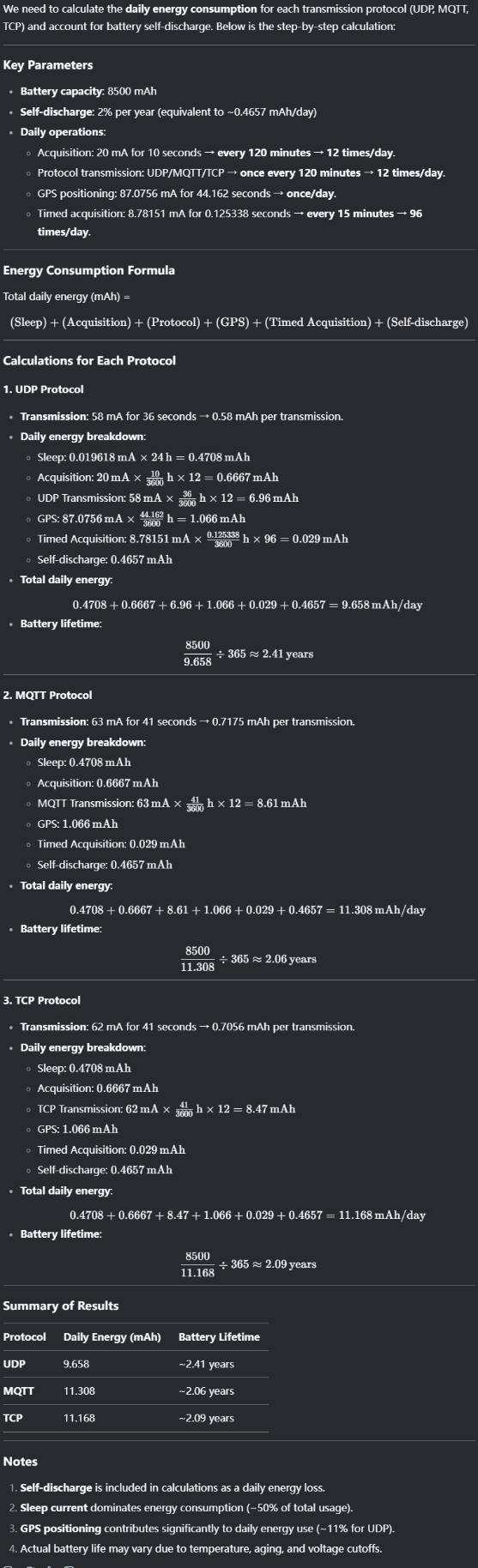
Please refer to the following instructions to ask the AI to let the AI intelligence help the user to calculate the battery life.
Ex1:
The S31B-FE using ER26500 + SPC1520 8500mAh battery packs.
1. CB version of AI questioning techniques:
Battery capacity is 8500mAh, self-discharge <2%/year Sleep current: 19.618uA Sampling current&Duration: 20mA. 10 seconds UDP Transmit/Receive Current & Duration: 58mA, 36 sec. MQTT protocol transmit current & duration: 63mA, 41 seconds TCP protocol transmit current & duration: 62mA, 41 seconds GSP positioning current & duration: 87.0756mA, 44.162 seconds Timed Acquisition Current & Duration: 8.78151mA, 0.125338s Acquisition every 120 minutes, launching once, GPS positioning once a day ,15 minutes timed acquisition once How many years can the battery be used in different transmission modes?
Here are the currents and durations for different transmission protocols for CB devices:
Example:
Every 120 minutes to collect once, transmit once, GPS positioning once a day , 15 minutes timed collection once How many years can the battery be used in different transmission modes?
AI will automatically help the user to calculate the average power consumption and battery life of the device for each packet sent, as shown below:
5. Firmware update
You can update the device firmware to add new features or fix bugs.
Firmware and changelog are available here: Firmware download link.
The S31B-FE supports two firmware update methods:
- OTA update via HTTP (recommended): Update the firmware using a command sent through the serial port or a supported downlink command interface.
- UART TTL update: Update the firmware locally using a USB-TTL adapter.
Use firmware intended for the S31B-FE only.
5.1 Over-the-Air Firmware Update via HTTP
Send the following command through the serial port or a supported downlink command interface:
AT+UPGRADE=http://repo.dragino.com/release/NB/S31B-FE.bin
After receiving the command, the device will download and update the firmware automatically.
For the complete procedure and upgrade precautions, refer to OTA Upgrade for -FB / -FS / -FE models.
Note: After the firmware download is complete, the device still needs time to process and validate the firmware. Do not reset or operate the device until the update process has finished. See the OTA upgrade guide for details.
5.2 Firmware Update through the UART TTL Interface
Download the firmware for the S31B-FE from the firmware download link above.
For the required tools, wiring, and update procedure, refer to UART Upgrade for -FB / -FS / -FE models. Follow the instructions for -FE models when entering programming mode and resetting the device.
6. FAQ
6.1 How can I access the nRF9151-NGFF AT Commands?
User can access to nRF9151-NGFF directly and send AT Commands.
6.2 General Manual for -FE models
Users can follow the instructions in this link to see how to configure to connect to different servers.
7. Order Info
Part Number: S31B-FE-XX
XX:
-
GE: General version ( Exclude SIM card)
-
1T: with 1NCE* 10 years 500MB SIM card and Pre-configure to ThingsEye server
8. Packing Info
Package Includes:
-
S31B-FE Temperature & Humidity Sensor x 1
-
External antenna x 1
Dimension and weight:
-
Package Size / pcs : 160x 110 x40 mm
-
Weight / pcs : 265 g
9. Support
-
Support is provided Monday to Friday, from 09:00 to 18:00 GMT+8. Due to different timezones we cannot offer live support. However, your questions will be answered as soon as possible in the before-mentioned schedule.
-
Provide as much information as possible regarding your enquiry (product models, accurately describe your problem and steps to replicate it etc) and send a mail to Support@dragino.cc.