LTC1/LTC2-FB/FS
1. Introduction
1.1 What is LTC1/LTC2-FB NB-IoT/LTE-M Temperature Transmitter
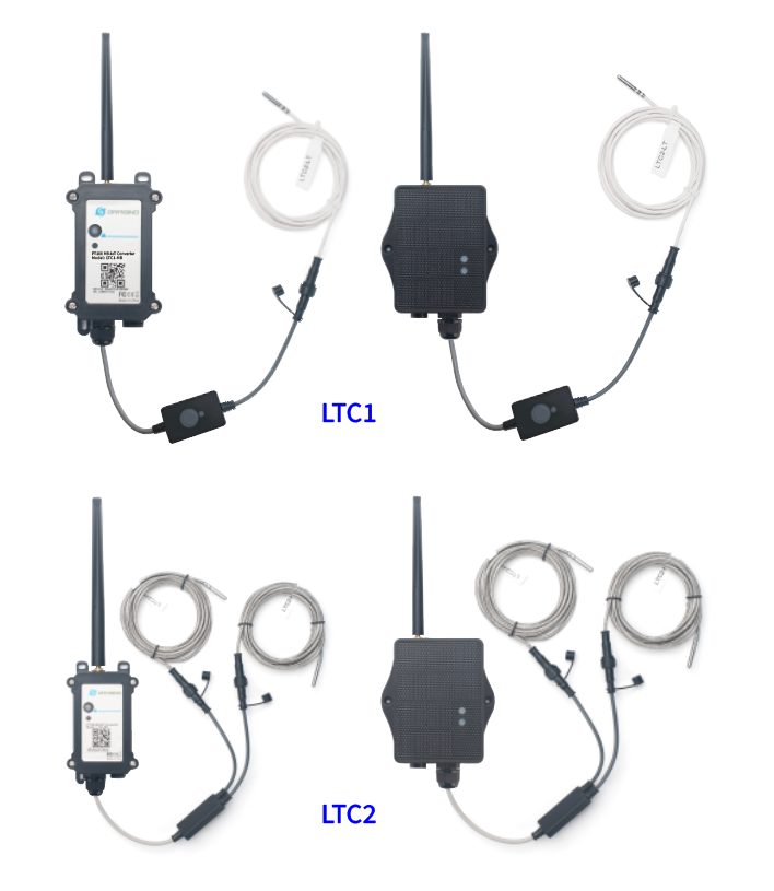
The Dragino LTC1/LTC2-FB Industrial NB-IoT/LTE-M Temperature Transmitter is designed to monitor temperature for different environment. It supports to read PT100 probe and convert the value to temperature and then upload to IoT server via NB-IoT network*.
LTC2-FB/FS has two internal 24-bit ADC interfaces.
LTC1-FB/FS has one internal 24-bit ADC interfaces.
LTC1/LTC2-FB/FS supports BLE configure and wireless OTA update which make user easy to use.
LTC1/LTC2-FB/FS supports different uplink methods include TCP, MQTT, UDP or MQTTs for different application requirement. and Support Uplinks to various IoT Servers.
LTC1/LTC2-FB/FS is powered by 8500mAh Li-SOCI2 battery or solar powered + Li-ion battery, It is designed for long term use up to several years. (Real-world battery life depends on the use environment, update period and uplink method. Please check related Power Analyze report).
*make sure you have NB-IoT or CAT-M1 coverage locally.
1.2 Features
- NB-IoT Bands: B1/B2/B3/B4/B5/B8/B12/B13/B17/B18/B19/B20/B25/B28/B66/B70/B85 @H-FDD
- CAT-M1 / LTE-M Bands: B1/B2/B3/B4/B5/B8/B12/B13/B18/B19/B20/B25/B26/B28/B66/B85/B106
- Ultra-low power consumption
- For LTC1-FB/FS: max: 1 x monitor temperature channels
- For LTC1-FB/FS: Press the button to immediately take a sample and upload a data packet.
- For LTC2-FB/FS: max: 2 x monitor temperature channels
- Support 3 -wire PT-100
- Temperature alarm
- Multiply Sampling and one uplink
- Uplink via MQTT, MQTTs, TCP, UDP
- Support Bluetooth v5.1 remote configure and update firmware
- Uplink on periodically
- Downlink to change configure
- 8500mAh Battery for long term use (LTC1/LTC2-FB)
- Solar panel + 3000mAh Li-ion battery (LTC1/LTC2-FS)
1.3 Specification
Common DC Characteristics:
- Supply Voltage: Built-in Battery , 3.0v ~ 3.6v
- Operating Temperature: -40 ~ 85°C
Temperature Sensor:
- Range: -40 to + 80°C
- Accuracy: ±0.2 @ 0-90 °C
- Resolution: 0.1°C
- Long Term Shift: <0.03 °C/yr
NB-IoT Spec:
NB-IoT Module: NRF9151-NGFF
Support Bands:
- B1 @H-FDD: 2100MHz
- B2 @H-FDD: 1900MHz
- B3 @H-FDD: 1800MHz
- B4 @H-FDD: 2100MHz
- B5 @H-FDD: 860MHz
- B8 @H-FDD: 900MHz
- B12 @H-FDD: 720MHz
- B13 @H-FDD: 740MHz
- B17 @H-FDD: 730MHz
- B18 @H-FDD: 870MHz
- B19 @H-FDD: 870MHz
- B20 @H-FDD: 790MHz
- B25 @H-FDD: 1900MHz
- B28 @H-FDD: 750MHz
- B66 @H-FDD: 2000MHz
- B70 @H-FDD: 2000MHz
- B85 @H-FDD: 700MHz
Battery:
- Li/SOCI2 un-chargeable battery
- Capacity: 8500mAh
- Self Discharge: <1% / Year @ 25°C
- Max continuously current: 130mA
- Max boost current: 2A, 1 second
Power Consumption
- STOP Mode: 10uA @ 3.3v
- Max transmit power: 350mA @ 3.3v
1.4 Applications
- Logistics and Supply Chain Management
- Food management
- Cold chains solution
- Industrial Monitoring and Control
1.5 Sleep mode and working mode
Deep Sleep Mode: Sensor doesn't have any NB-IoT/CAT-M1 activate. This mode is used for storage and shipping to save battery life.
Working Mode: In this mode, Sensor will work as NB-IoT Sensor to Join NB-IoT network and send out sensor data to server. Between each sampling/tx/rx periodically, sensor will be in IDLE mode), in IDLE mode, sensor has the same power consumption as Deep Sleep mode.
1.6 Button & LEDs
| Behavior on ACT | Function | Action |
|---|---|---|
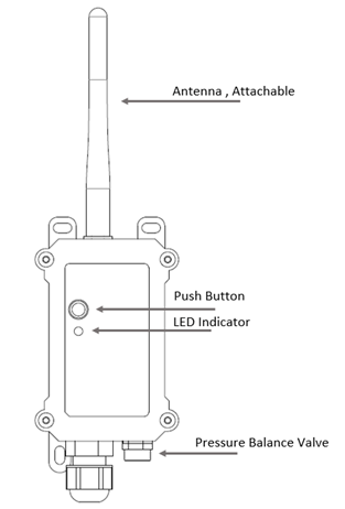
 1~3s 1~3s | Send an uplink | If sensor has already attached to NB-IoT/CAT-M1 network, sensor will send an uplink packet, blue led will blink once. |
 >3s >3s | Active Device | Green led will fast blink 5 times. And then start to attach NB-IoT/CAT-M1 network. |
 x5 x5 | Deactivate Device | Red led will solid on for 5 seconds. Means device is in Deep Sleep Mode. |
| x1 | Toggle Serial Communication | Press the ACT button once to activate the serial communication function, and Ready will be displayed in the serial tool. |
Note: When the device is executing a program, the buttons may become invalid. It is best to press the buttons after the device has completed the program execution.
1.7 BLE connection
LTC1/LTC2-FB support BLE remote configure and firmware update.
BLE can be used to configure the parameter of sensor or see the console output from sensor. BLE will be only activate on below case:
- Press button to send an uplink
- Press button to active device.
- Device Power on or reset.
If there is no activity connection on BLE in 60 seconds, sensor will shut down BLE module to enter low power mode.
1.8 Pin Definitions , Switch & SIM Direction
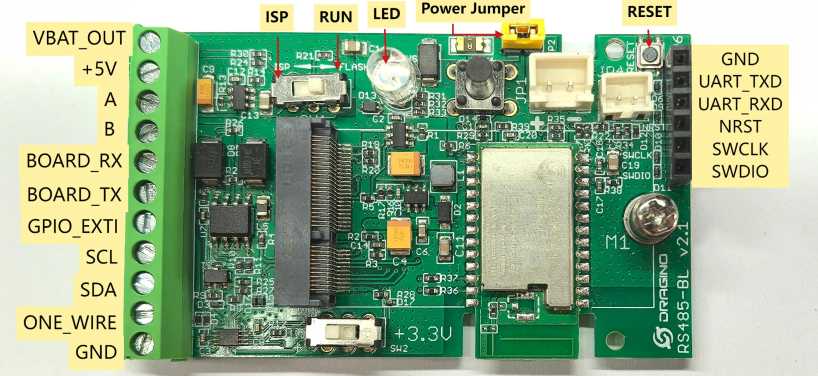
1.8.1 Jumper JP2
Power on Device when put this jumper.
Power off device when take out this jumper
1.8.2 BOOT MODE / SW1
1) ISP: upgrade mode, device won't have any signal in this mode. but ready for upgrade firmware. LED won't work. Firmware won't run.
2) Flash: work mode, device starts to work and send out console output for further debug
Due to hardware limitations of the NRF9151-NGFF module, this switch cannot actually control the NRF9151-NGFF module.
1.8.3 Reset Button
Press to reboot the device.
1.8.4 SIM Card Direction
See this link. How to insert SIM Card.
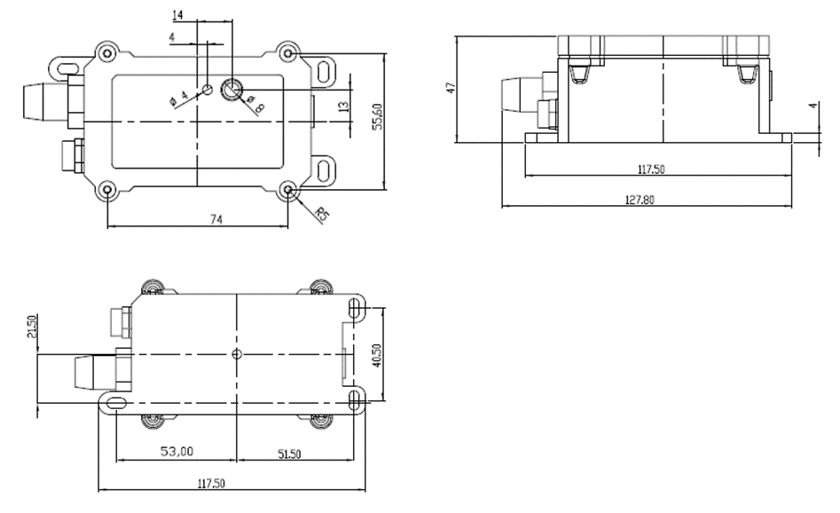
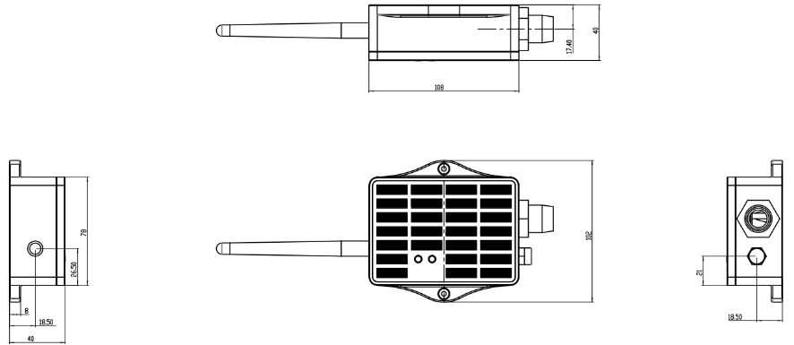
1.9 Mechanical
1.9.1 for FB version
1.9.2 for FS version
1.10 Probe Variant
LTC1/LTC2-FB provide default probe version. See below for the variant:
| Model | Photo | Description |
|---|---|---|
| DR-SI | 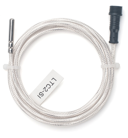 | Standard IP68 Probe Version:
|
| DR-LT | 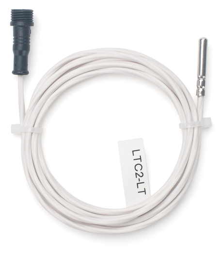 | Low Temperature Version:
|
| DR-HT | 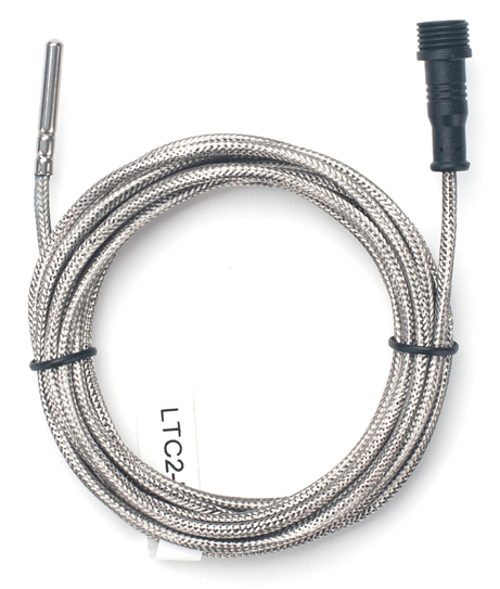 | High Temperature Version:
|
| DR-UHT | 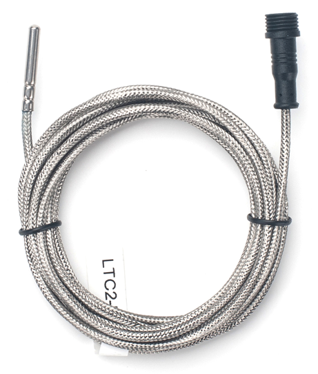 | Ultra High Temperature Version:
|
| DR-FSA | 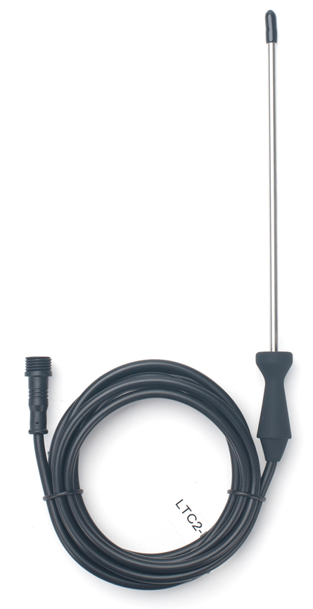 | Food Safety Version:
|
| DR-FT | 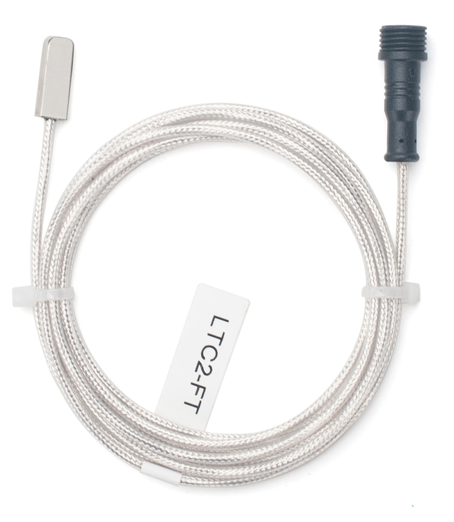 | Flat Type Version:
|
2. Use LTC1/LTC2-FB to communicate with IoT Server
2.1 Send data to IoT server via NB-IoT network
The LTC1/LTC2-FB is equipped with a NB-IoT module, the pre-loaded firmware in LTC1/LTC2-FB will get environment data from sensors and send the value to local NB-IoT network via the NB-IoT module. The NB-IoT network will forward this value to IoT server via the protocol defined by LTC1/LTC2-FB.
Below shows the network structure:
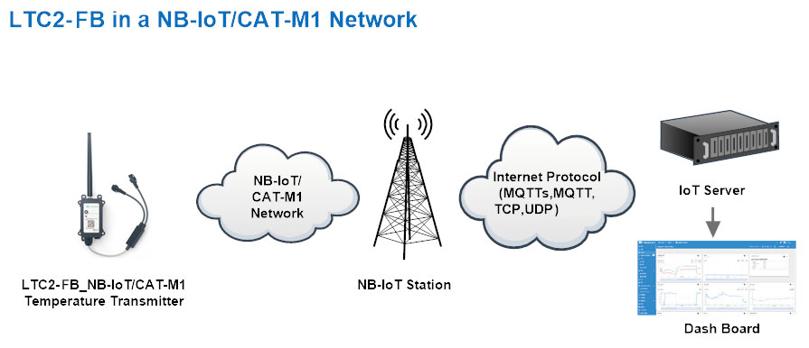
There are two version: -GE and -1T version of LTC1/LTC2-FB.
GE Version: This version doesn't include SIM card or point to any IoT server. User needs to use AT Commands to configure below two steps to set LTC1/LTC2-FB send data to IoT server.
-
Install NB-IoT SIM card and configure APN. See instruction of Attach Network.
-
Set up sensor to point to IoT Server. See instruction of Configure to Connect Different Servers.
Below shows result of different server as a glance.
| Servers | Dash Board | Comments |
|---|---|---|
| Node-Red | 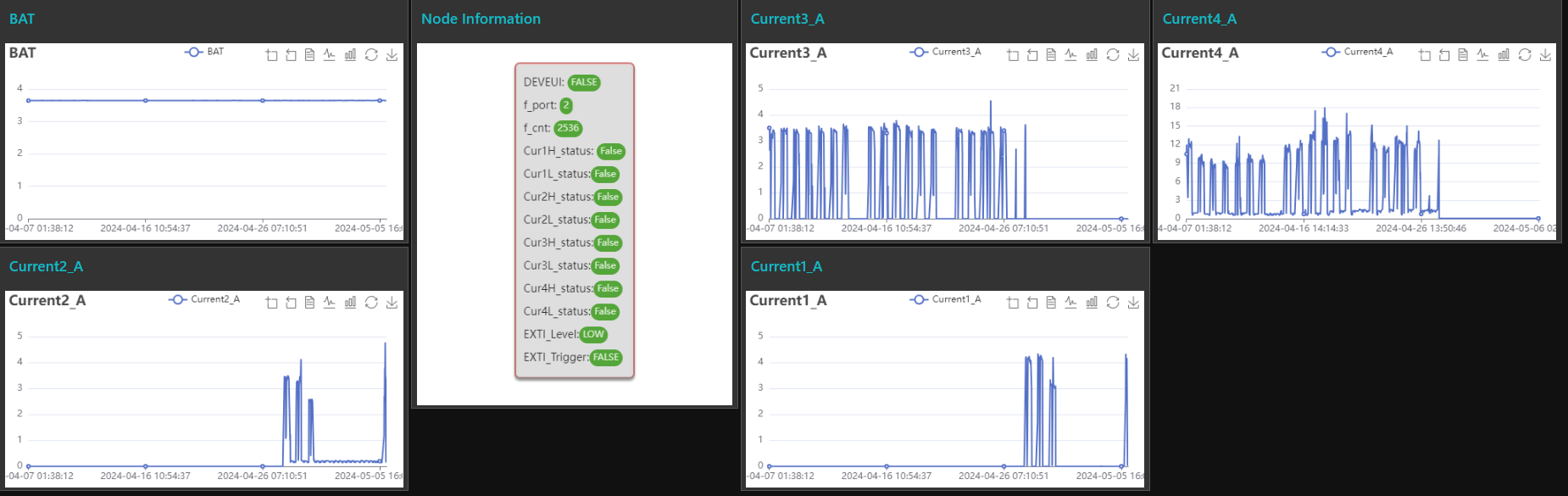 | |
| DataCake | 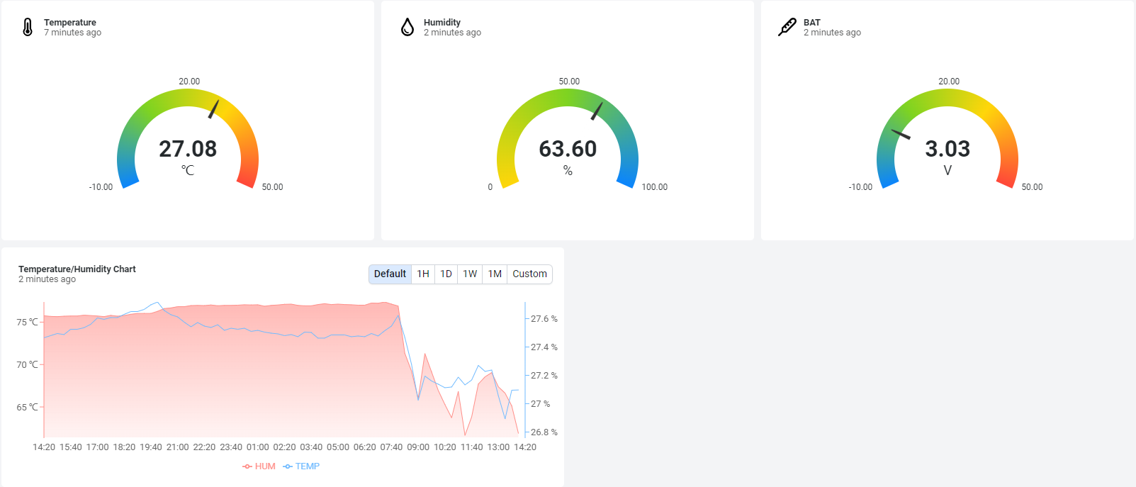 | |
| Tago.IO | ||
| General UDP | Raw Payload. Need Developer to design Dash Board | |
| General MQTT | Raw Payload. Need Developer to design Dash Board | |
| ThingSpeak | 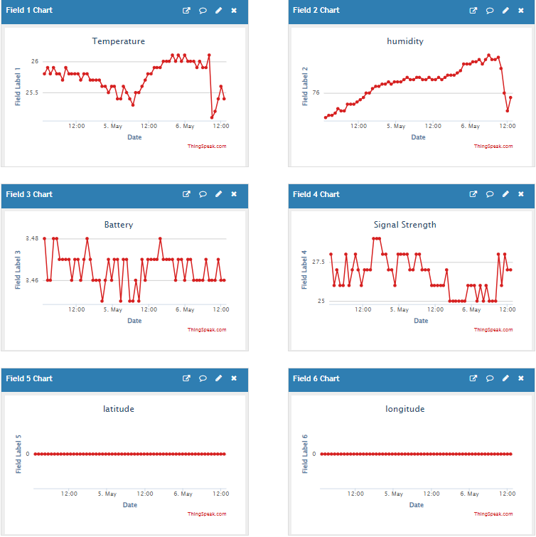 | |
| ThingsBoard | 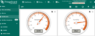 |
1T Version: This version has 1NCE SIM card pre-installed and configure to send value to ThingsEye. User Just need to select the sensor type in ThingsEyeand Activate LTC1//LTC2-FB/FS and user will be able to see data in ThingsEye. See here for ThingsEye Config Instruction.
2.2 Payload Types
LTC1/LTC2-FB supports JSON payloads only. Use AT+PRO to select the connection protocol with the corresponding parameters:
AT+PRO=2,0// UDP connection with JSON payloadAT+PRO=3,0// MQTT connection with JSON payloadAT+PRO=4,0// TCP connection with JSON payload
2.2.1 General Json Format(Type=0)
When using the LTC1-CB module, the temperature2 is invalid and is always 0.0 degrees.
This is the General Json Format. As below:
{"IMEI":"355025934932888","IMSI":"460087023300088","Model":"LTC2-FB","fcnt":"0","signal":"29","bat":3.48,"temp1":25.9,"temp2":25.6,"L1":"0","H1":"0","L2":"0","H2":"0","i_flag":"0","time":"2026-9-22T06:33:48Z","latitude":0.000000,"longitude":0.000000,"gps_time":"00/00/00,00:00:00","1":["24.2,24.3,2026-9-16T09:04:39Z"],"2":["24.2,24.3,2026-9-16T09:19:39Z"],"3":["24.2,24.3,2026-9-16T09:34:39Z"],"4":["24.2,24.3,2026-9-16T09:49:39Z"],"5":["24.2,24.3,2026-9-16T10:04:39Z"],"6":["24.2,24.3,2026-9-16T10:19:39Z"],"7":["3046.3,-0.1,2106-2-5T14:32:37Z"],"8":["25.9,25.6,2026-9-22T06:33:48Z"]}
Example:
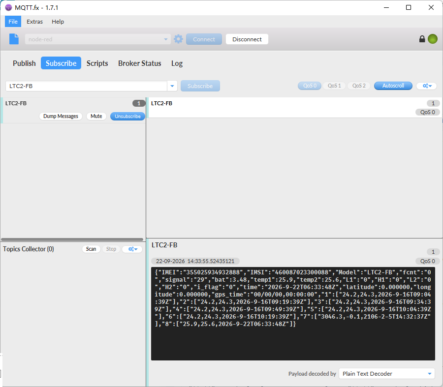
Notice, from above payload:
-
temp1, temp2, Battery, L1, H1, L2, H2, Fcnt, i_flag, Signal & time are the value at uplink time.
-
Json entry 1 ~ 8 are the last 1 ~ 8 sampling data as specify by AT+CLOCKLOG=1,65535,15,8 Command. Each entry includes (from left to right): temp1, temp2, Sampling time.
L1,H1,L2,H2
This data field shows whether the packet was generated by a temperature alarm.
"L1" stands for low temperature alarm,
"H1" stands for high temperature alarm.
"L2" stands for low temperature alarm,
"H2" stands for high temperature alarm.
Payload Analysis:
Device ID(f+IMEI): 355025934932888
SIM Card ID(f+IMSI): 460087023300088
BAT (Battery Info): 3.48V
Signal Strength:
NB-IoT Network signal Strength.
Ex1: 22
0 -113dBm or less
1 -111dBm
2...30 -109dBm... -53dBm
31 -51dBm or greater
99 Not known or not detectable
Interrupt:
This data field shows if this packet is generated by interrupt or not.
Example:
If Json payload is 00 : Normal uplink packet.
If Json payload is 01 : Interrupt Uplink Packet.
L1:
This field indicates the lower limit alarm status for temperature probe 1.
Example:
If Json payload is 00 : No alarm was triggered
If Json payload is 01 : This data packet triggered a lower limit alarm for Temperature 1.
H1:
This field indicates the upper limit alarm status for temperature probe 1.
Example:
If Json payload is 00 : No alarm was triggered
If Json payload is 01 : This data packet triggered the upper limit alarm for temperature 1.
L2:
This field indicates the lower limit alarm status for temperature probe 2.
Example:
If Json payload is 00 : No alarm was triggered
If Json payload is 01 : This data packet triggered a lower limit alarm for Temperature 2.
H2:
This field indicates the upper limit alarm status for temperature probe 2.
Example:
If Json payload is 00 : No alarm was triggered
If Json payload is 01 : This data packet triggered the upper limit alarm for temperature 2.
Latitude:
EX1: 0x00000000 // Locating fails or is not enabled.
EX2: 22.706410 // Latitude: 22.706410
Longitutde:
EX1: 0x00000000 // Locating fails or is not enabled.
EX2: 114.244730 // Longitutde: 114.244730
GPS_Timestamp:
EX1: 0x00000000 // The value is "1970-01-01T00:00:00Z" in JSON format. The initial GPS time is not refreshed if GPS positioning is disabled or fails.
EX2: 2024-07-01 15:23:09
temp1
payload is: 26.7 degree
payload is: -19.3 degrees.
If the value is -327.6, it means the channel1 PT100 probe is not connected.
If the value is -983, it means the PT100 converter is not connected.
temp2
Notice: When using the LTC1-FB module, the temperature2 is invalid and is always 0.0 degrees.
payload is: 27.4 degree
payload is: -19.3 degrees.
If the value is -327.6, it means the channel2 PT100 probe is not connected.
If the value is -983, it means the PT100 converter is not connected.
TimeStamp:
Unit TimeStamp Example: 676b5f85(H) = 1735090053(D)
Put the decimal value into this Epoch Converter to get the time.
3. Configure LTC1/LTC2-FB
3.1 Configure Methods
LTC1/LTC2-FB supports below configure method:
-
AT Command via Bluetooth Connection (Recommended): BLE Configure Instruction.
-
AT Command via UART Connection : See UART Connection.
3.2 Serial Access Password
Due to limitations of the NRF9151-NGFF module, the serial communication function remains active for only 5 minutes. If this time is exceeded, you must press the ACT button once to reactivate the chip’s serial communication function.
After the Bluetooth or UART connection is successful, use the Serial Access Password to enter the AT command window.
The label on the box of the node will print the initial password: AT+PIN=xxxxxx, and directly use the six-digit password to access the AT instruction window.
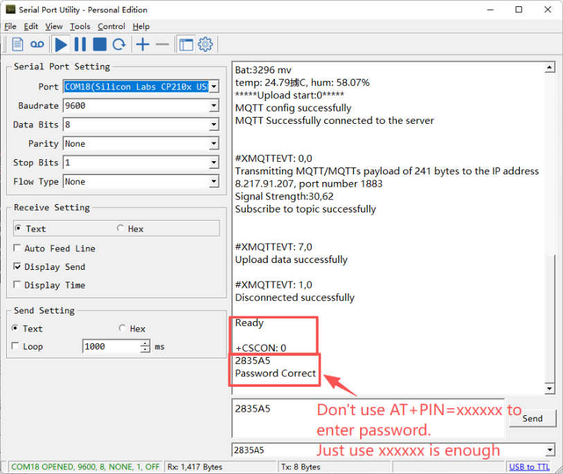
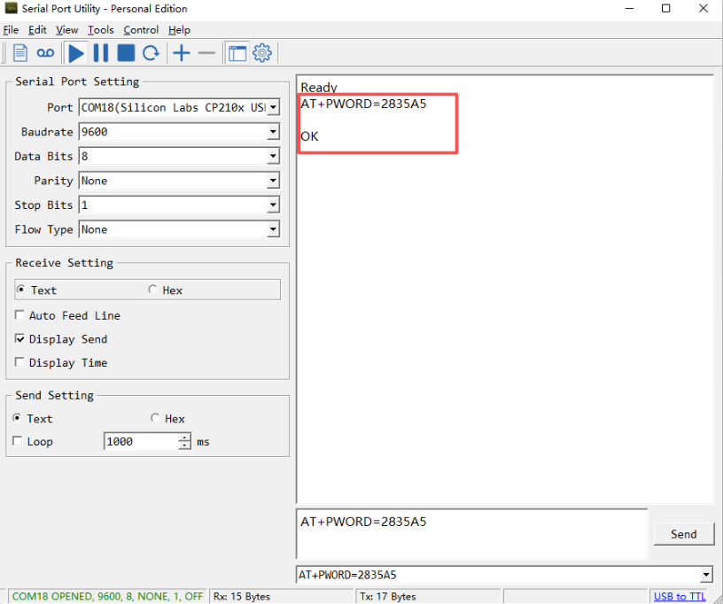
If you need to change the password, use **AT+PWORD=**xxxxxx (6 characters), -FB nodes only support lowercase letters.
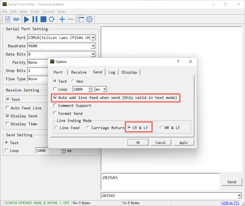
After entering the command, you need to add a line break, and you can also set automatic line breaks in the Bluetooth tool or UART connection tool.
3.3 AT Commands Set
AT+<CMD>? : Help on <CMD>
AT+<CMD> : Run <CMD>
AT+<CMD>=<value> : Set the value
AT+<CMD>=? : Get the value
AT+MODEL : Get module information
ATZ : Trig a reset of the MCU
AT+DEUI : Get or set the Device ID
AT+SLEEP : Get or set the sleep status
AT+DEBUG : Set more info output
AT+SERVADDR: Get or Set the Server address
AT+TDC : Get or set the application data transmission interval in s
AT+APN : Get or set the APN
AT+PRO : Get or Set usage agreement (2:UDP,3:MQTT,4:TCP)
AT+RXDL : Get or Set the receiving time
AT+DNSCFG : Get or Set DNS Server
AT+SFNT : Get or Set the time to join the network
AT+BKDNS : Get or Set dynamic domain name resolution IP
AT+GDNS : Get or Set the DNS
AT+TLSMOD : Get or Set the TLS mode
AT+IPTYPE : Set the IPv4 or IPv6
AT+INTMOD : Get or Set the trigger interrupt mode (0:input,1:falling or rising,2:falling,3:rising)
AT+CLOCKLOG: Enable or Disable Clock Logging
AT+TIMESTAMP : Get or Set UNIX timestamp in second
AT+DOWNTE: Get or set the conversion between the standard version and 1T version downlinks
AT+QSW : Power on and power off BG95 module
AT+QBAND: Get or set Frequency Band
AT+IOTMOD: Configure Network Category to be Searched for under LTE RAT
AT+WMOD : Get or Set the Alarm Mode
AT+ALARM : Get or Set the Alarm Threshold
MQTT Management
AT+CLIENT : Get or Set the MQTT clientID
AT+UNAME : Get or Set the MQTT Username
AT+PWD : Get or Set the MQTT password
AT+PUBTOPIC: Get or set MQTT publishing topic
AT+SUBTOPIC: Get or set MQTT subscription topic
AT+MQOS : Set the QoS level of MQTT
GPS:
AT+GTIME : Extend the time to turn on GNSS
AT+QGPS : Turn off and on GPS
AT+QGTDC : Get or set GPS positioning interval in units of h
Information
AT+FDR : Reset Parameters to Factory Default
AT+PWORD : Get or set the System password
AT+LDATA : Get the last upload data
AT+GETSENSORVALUE : Returns the current sensor measurement
AT+GETLOG : Print serial port logs
AT+CFG : Print all settings
ATZ : Trig a reset of the MCU
3.4 Test Uplink and Change Update Interval
By default, Sensor will send uplinks every 20 min.
User can use below commands to change the uplink interval.
AT Command: AT+TDC
Example: AT+TDC=7200 // Set Update Interval to 7200 seconds
Downlink Commands: 0x01
Format: Command Code (0x01) followed by 3 bytes.
Example: 12 hours= 43200 seconds 43200(D)=0xA8C0(H)
Downlink Payload: **01 00 A8 C0** // AT+TDC=43200, Set Update Interval to 12 hours.
Note: User can also push the button for more than 1 second to activate an uplink.
3.5 Set the receiving time
Feature: Extend the receiving time
AT Command: AT+RXDL
Example: AT+RXDL=1000 // Set the receiving time delay to 1000ms
Downlink Commands: 0x03
Format: Command Code (0x03) followed by 3 bytes.
Example: Downlink Payload: 03 00 03 E8// AT+RXDL=1000
3.6 Reset
Feature: Trig a reset of the MCU.
AT Command: ATZ
Downlink Commands: 0x04FF
3.7 Trigger an uplink by external interrupt
LTC1/LTC2-FB has an external trigger interrupt function. Users can use the GPIO_EXTI pin to trigger the upload of data packets.
AT command:
-
AT+INTMOD // Set the trigger interrupt mode
-
AT+INTMOD=0 // Disable Interrupt
-
AT+INTMOD=1 // Trigger by rising and falling edge
-
AT+INTMOD=2 // Trigger by falling edge
-
AT+INTMOD=3 // Trigger by rising edge
Downlink Commands: 0x06
Format: Command Code (0x06) followed by 3 bytes.
Example1: Downlink Payload: 06 00 00 01// AT+INTMOD=1
Example2: Downlink Payload: 06 00 00 03// AT+INTMOD=3
3.8 Set the QoS level
This command is used to set the QoS level of MQTT.
AT command:
- AT+MQOS=xx // 0~2
Downlink command: 0x07
Format: Command Code (0x07) followed by 1 byte.
Ex1: Downlink payload: 0x0700 // AT+MQOS=0
Ex2: Downlink payload: 0x0701 // AT+MQOS=1
3.9 Clock logging
Sometimes when we deploy lots of end nodes in field. We want all sensors sample data at the same time, and upload these data together for analyze. In such case, we can use clock loging feature.
We can use this command to set the start time of data recording and the time interval to meet the requirements of the specific collection time of data.
AT command: AT+CLOCKLOG=a,b,c,d
a: 0: Disable Clock logging. 1: Enable Clock Logging
b: Specify First sampling start second: range (0 ~ 3599, 65535) // Note: If parameter b is set to 65535, the log period starts after the node accesses the network and sends packets.
c: Specify the sampling interval: range (0 ~ 255 minutes)
d: How many entries should be uplink on every TDC (max 32)
To disable clock recording, set the following parameters: AT+CLOCKLOG=1,65535,0,0
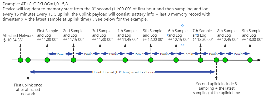
Example:
AT+CLOCKLOG=1,65535,1,8
After the node sends the first packet, data is recorded to the memory at intervals of 1 minute. For each TDC uplink, the uplink load will include: battery information + the last 5 memory records (payload + timestamp).
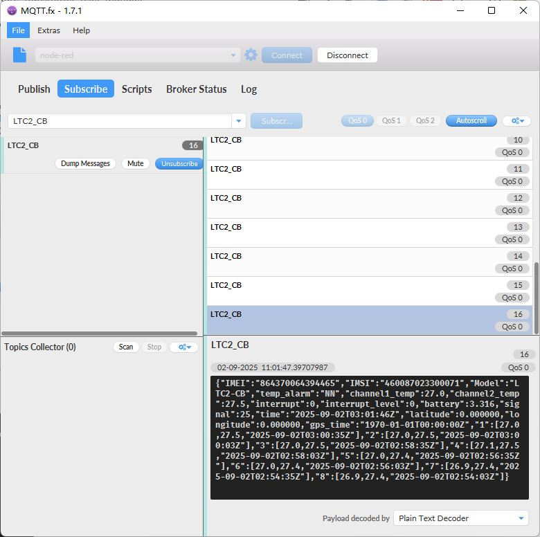
Note: Users need to synchronize the server time before configuring this command. If the server time is not synchronized before this command is configured, the command takes effect only after the node is reset.
Downlink command: 0x03
Format: Command Code (0x03) followed by 5 bytes.
- Example 1: Downlink Payload: 03 01 FFFF 0F 08 // Set SHT record time: AT+CLOCKLOG=1,65535,15,8
- Example 2: Downlink Payload: 03 01 04B0 0F 08 // Set SHT record time: AT+CLOCKLOG=1,1200,15,8
Note: When entering the downlink payload, there must be no Spaces between bytes.
3.10 Set the TLS mode
Refer to this link (MQTT Connection to send data to MQTT platformto use the TLS mode.
AT Command: AT+TLSMOD
Example 1: AT+TLSMOD=0,0 // Disable TLS Mode.
Example 2:
- AT+TLSMOD=1,0 // No authentication
- AT+TLSMOD=1,1 // Perform server authentication
- AT+TLSMOD=1,2 // Perform server and client authentication if requested by the remote server
Downlink command: 0x09
Format: Command Code (0x09) followed by 2 bytes.
Example1: Downlink Payload: 09 00 00 // AT+TLSMOD=0,0
Example2: Downlink Payload: 09 01 02 // AT+TLSMOD=1,2
3.11 Set the search network time
Feature: Get or Set the time to join the network(unit: minutes).
AT Command: AT+SFNT
Example: AT+SFNT=10 // Set the search time to 10 minutes.
Downlink command: 0x13
Format: Command Code (0x13) followed by 1 byte.
Example: Downlink Payload: 13 0A// AT+SFNT=10
3.12 Set Alarm Threshold
Feature: Set Alarm Threshold. (Unit: ℃)
AT Command: AT+ALARM
The first parameter sets the low limit of channel 1, and the second parameter sets the high limit of channel 1.
The third parameter sets the low limit for channel 2, and the fourth parameter sets the high limit for channel 2.
Example:
- AT+ALARM=-200,800,-200,800 // Channel 1 & Channel 2 operating temp: -200℃~800℃,alarm when out of range.
- AT+ALARM=10,100,10,101 // Channel 1 operating temp: 10℃~100℃; Channel 2 operating temp: 10℃~101℃, alarm when out of range.
Downlink Command: 0x08
Format: Command Code (0x08) followed by 8 bytes.
Each two bytes after the function code 0xA7 is a parameter, corresponding to the four parameters of AT+ALARM in sequence.
Example:
- Downlink payload: 0x08FF380320FF380320 // Same as AT+ALARM=-200,800,-200,800
- Downlink payload: 0x08000A0064000A0065 // Same as AT+ALARM=10,100,10,101
Note: For negative temperature -200℃: 65536-200= 65336(D) = 0XFF38(H)
3.13 Factory data reset
Two different restore factory Settings configurations.
AT command:
- AT+FDR// Reset Parameters to Factory Default.
3.14 Set GTIME open time
Extend the time to turn on GNSS. The automatic GPS location time is extended when the node is activated.
AT Command: AT+GTIME
Example: AT+GTIME=30 // Set the GPS positioning time to 30 seconds
Downlink command: 0x10
Format: Command Code (0x10) followed by 2 bytes.
Example: Downlink Payload: 10 00 1E // AT+GTIME=30
3.15 Turn on/off GPS
AT Command: AT+QGPS
- Ex1: AT+QGPS=0 // Turn off GPS
- Ex2: AT+QGPS=1 // Turn on GPS
Downlink command: 0x11
Format: Command Code (0x11) followed by 1 byte.
Example: Downlink Payload: 11 01 // AT+QGPS=1
3.16 Set GPS positioning interval
Feature: Set GPS positioning interval (unit: hour).
When GPS is enabled, the node automatically locates and uplinks each time it passes GTDC time after activation.
AT Command: AT+QGTDC
Example: AT+QGTDC=24 // Set the GPS positioning interval to 24h.
Downlink command: 0x12
Format: Command Code (0x12) followed by 3 bytes.
Example: 24 hours: 24(D)=0x18(H)
Downlink Payload: 12 00 00 18 // AT+QGTDC=24
3.17 Uplink log query
- AT command: AT+GETLOG
This command can be used to query upstream logs of data packets.
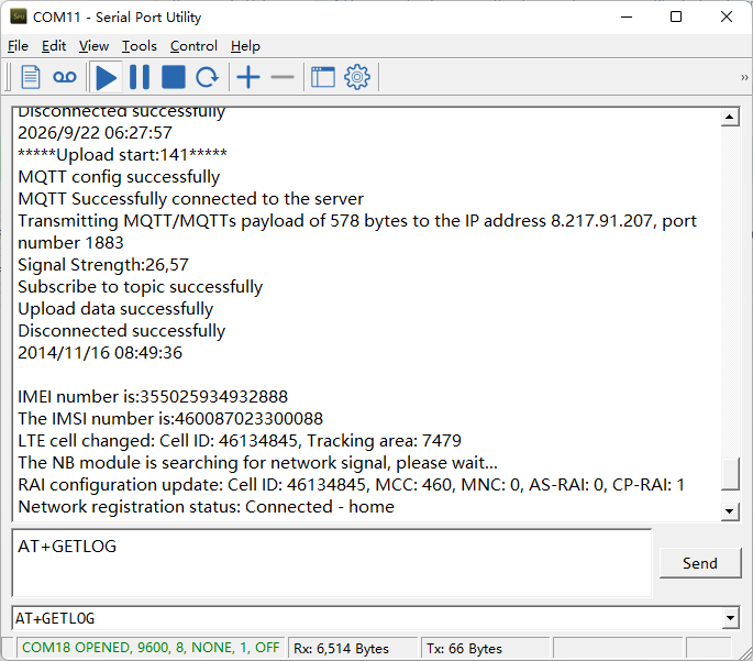
3.18 Debug mode
Feature: Since the serial communication feature of the NRF9151 module requires activation, this command is intended for users who need to use the serial port for extended periods of time.
AT command: AT+DEBUG
| Command Example | Function |
|---|---|
| AT+DEBUG=1 | Enter debugging mode |
| AT+DEBUG=0 | Exit debugging mode,Serial port function disabled |
Note:1. This feature remains active for only 5 minutes; it will automatically turn off after 5 minutes.2. Keeping the serial port open continuously increases power consumption in sleep mode; the continuous current is 900 μA.
3.19 Configure Network Category to be Searched for under LTE RAT.
By default, the NB-IoT network is turned off, and only the LTE-M network is enabled. If a user needs to use the NB-IoT network, they must enable it themselves.
AT command: AT+IOTMOD=a,b,c
a: 0: Disenable eMTC; 1: Enable eMTC
b: 0: Disenable NB-IoT ; 1. Enable NB-IOT
c: Priority: If two network categories are enabled simultaneously, the device will give priority to the configured category.
Ext1: AT+IOTMOD=1,1,2 ----> Indicates that both eMTC and NB-IoT are enabled, with priority given to the NB-IoT network type.
4. Battery & Power Consumption
LTC1/LTC2-FB use ER26500 + SPC1520 battery pack and LTC1/LTC2-FS use 3000mAh Recharable Battery with Solar Panel. See below link for detail information about the battery info and how to replace.
To be updated
5. Firmware update
5.1 Over-the-Air (OTA) Firmware Update via HTTP
Note: Users can upload the firmware binary to any public HTTP server (not a local/private network address) that the device can access, then use the following method to upgrade
Perform the following steps:
① Place the firmware binary (e.g., LTC2-FB.bin) on an HTTP-accessible server.
② Use a serial port or send the following command to the device: AT+UPGRADE=<firmware_url>
Example: AT+UPGRADE=http://repo.dragino.com/release/NB/LTC2-FB.bin
After the node receives the upgrade command via downlink, it will perform the upgrade automatically as shown below:
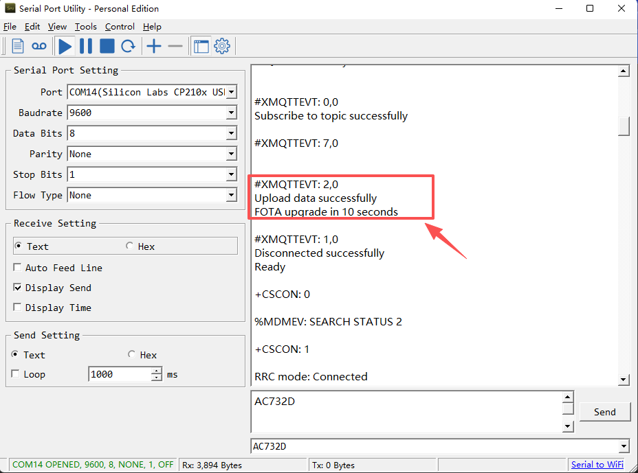
5.2 Firmware Update through UART TTL interface
-
Firmware and changelog can be downloaded from : Firmware download link
-
For detailed instructions on how to perform an update via USB TTL, please refer to this link: UART Upgrade for -FB/-FS/-FE models
6. FAQ
6.1 How can I access the NRF9151-NGFF AT Commands?
User can access to NRF9151-NGFF directly and send AT Commands.
See NRF9151-NGFF AT Command set
6.2 General Manual for -FB , -FS models
Users can follow the instructions in this link to see how to configure to connect to different servers.
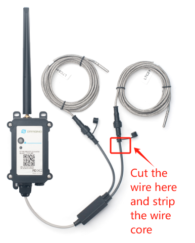
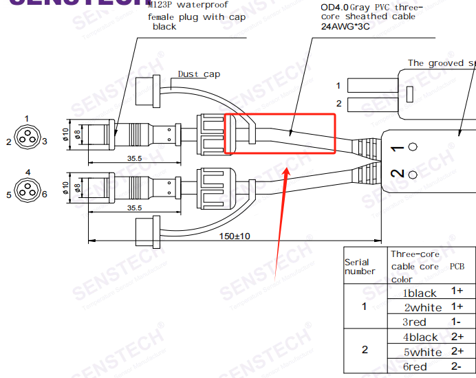
6.3 How do users connect custom PT100 sensors?
- The user needs to cut off one end of the original probe and peel off the wire core.
- Connect according to the corresponding positive and negative poles.
6.4 Why is there no LED response when I press the button on the solar panel model?
If the LED does not light up when you press the button, it may be because the battery has entered protection mode.
Solution: To reactivate the battery, simply expose the solar panel to direct sunlight. For more details, please refer to: Battery Protection State (Apply to Solar Panel + Li-ion battery)
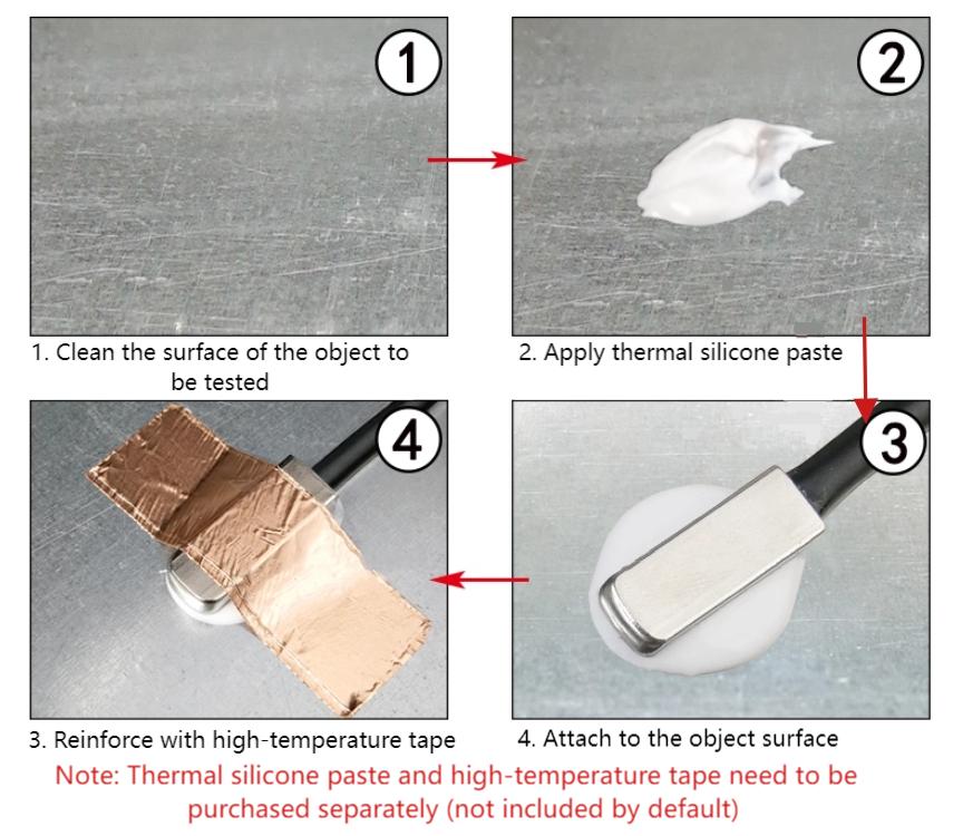
6.5 How to fix the FT -- Flat Type probe to surface?
6.6 Does this device support GPS positioning?
Yes. This device supports GPS function and can report latitude and longitude coordinates in the uplink payload.
For configuration and usage details, please refer to: Add Location Data on Uplink Packet
7. Order Info
Notice: This part number doesn't include the Temperature sensor. Users need to purchase separately.
Part Number: LTC1-FB/FS-XX or LTC2-FB/FS-XX
XX:
-
GE: General version ( Exclude SIM card)
-
1T: with 1NCE * 10 years 500MB SIM card and Pre-configure to ThingsEye server
Probe Options: DR-SI, DR-LT, DR-HT, DR-FSA, DR-FT
8. Packing Info
Package Includes:
- LTC1/LTC2-FB -- NB-IoT/LTE-M Temperature Transmitter x 1
Dimension and weight:
- Device Size: cm
- Device Weight: g
- Package Size / pcs : cm
- Weight / pcs : g
9. Support
- Support is provided Monday to Friday, from 09:00 to 18:00 GMT+8. Due to different timezones we cannot offer live support. However, your questions will be answered as soon as possible in the before-mentioned schedule.
- Provide as much information as possible regarding your enquiry (product models, accurately describe your problem and steps to replicate it etc) and send a mail to support@dragino.com