General Manual for -FB, -FS models
1. The use of this guideline
This configure instruction is for Dragino NB-IoT models with -FB or -FS suffix, for example S31-FB. These models use the same NB-IoT Module NRF9151-NGFF and has the same software structure. The have the same configure instruction to different IoT servers. Use can follow the instruction here to see how to configure to connect to those servers.
2. Attach Network
2.1 General Configure to attach network
To attache end nodes to NB-IoT or LTE-M Network, You need to:
- Get a NB-IoT or LTE-M SIM card from Service Provider. (Not the same as the SIM card we use in mobile phone)
- Power Off End Node ( See below for the power off/on position)
- Insert the SIM card to Sensor. ( See below for direction)
- Power On End Node
- Configure APN in the sensor (AT+APN=
), example AT+APN=iot.1nce.net
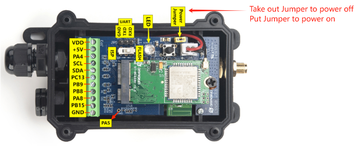
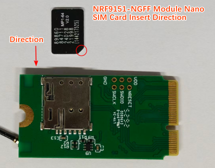
After doing above, the end nodes should be able to attach to NB-IoT network .
The FB/FS models are based on Nordic nRF9151, supporting LTE bands: **B1/B2/B3/B4/B5/B8/B12/B13/B14/B17/B18/B19/B20/B25/B26/B28/B66 **Make sure you use a NB-IoT SIM card with matching bands.
Make sure you use a the NB-IoT or LTE-M SIM card.
| SIM Provider | AT+APN= | NB-IoT Coverage | LTE-M Coverage | Comments |
| 1NCE | iot.1nce.net | Austria, Belgium, Bulgaria, China, Croatia, Czech Republic, Denmark, Estonia, Finland, Germany, Great Britain, Greece, Hungary, Ireland,Italy, Latvia, Malta, Netherlands, Norway, Portugal, Puerto Rico, Russia, Slovak,Republic, Slovenia, Spain, Sweden, Switzerland, Taiwan, USA, US Virgin Islands | Argentina, Austria, Australia, Belgium, Canada, Denmark,Estonia, Finland, France, Germany, Great Britain, Hungary, Ireland, Japan,Jersey, Korea, Repiblic of, Latvia, Luxembourg, Mexico, Netherlands, New Zealand, Norway, Poland, Puerto Rico, Romania, Spain, Sweden, Switzerland,Taiwan, USA, US Virgin Islands. | UK: Band20 |
| China Mobile | No need configure | China Mainland, HongKong | ||
| China Telecom | ctnb | China Mainland |
2.2 Speed Up Network Attach time
nRF9151 supports multiple bands and will scan one by one to attach. This may take a long time or even cause attach failure showing Signal Strength: 99. User can lock the band to specify band for its operator to make this faster.
Notice: When configuring the frequency band, you must first send the command `AT+CFUN=0` to disable the module's RF functionality before proceeding with the configuration. Otherwise, sending the command to lock the frequency band will only return "ERROR".AT%XBANDLOCK? // Check current used frequency band
AT%XBANDLOCK=1,"10000000" // Set to use 1 frequency band. Band 8
AT%XBANDLOCK=1,"10000010" // Set to use 2 frequency bands. Band 2 and Band 8
Notice:
- Parameter 1: Set to 1
- Parameter 2: The position number of 1 indicates which band to enable (counting from right to left)Recommended band settings by operator:
| Operator | Recommended AT%XBANDLOCK |
| China Mobile/Telecom | AT%XBANDLOCK=1,"00010000" |
| Europe General | AT%XBANDLOCK=1,"10000000000010000000" |
| Verizon (US) | AT%XBANDLOCK=1,"1000000000000" |
| AT&T (US) | AT%XBANDLOCK=1,"100000001010" |
After connection is successful, user can use AT%XBANDLOCK? to check which band is actually in used.
By default, device will search network for 5 minutes. User can set the time to 10 minutes by AT+CSQTIME=10 so it can search longer.
3. Configure to connect to different servers
3.1 General UDP Connection
The NB-IoT Sensor can send packet to server use UDP protocol.
3.1.1 Simulate UDP Connection by PC tool
We can use PC tool to simulate UDP connection to make sure server works ok.
3.1.2 Configure NB-IoT Sensor
3.1.2.1 AT Commands
AT Commands:
- AT+PRO=2,5 // Set to use UDP protocol to uplink ,Payload Type select JSON payload
- AT+SERVADDR=8.217.91.207,1999 // Set UDP server address and port
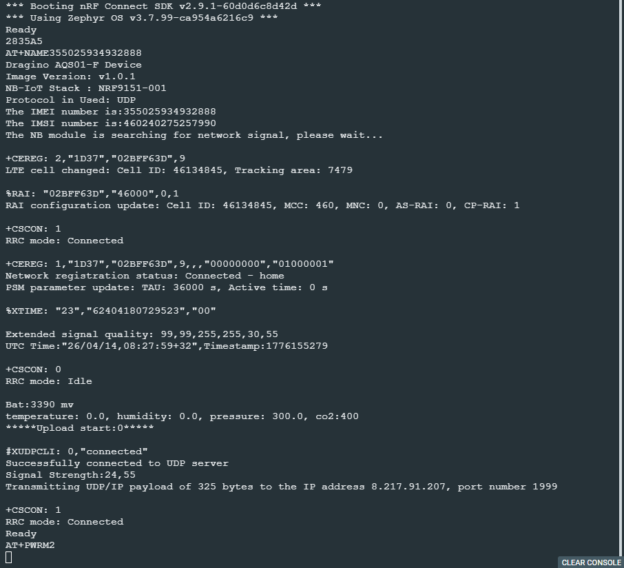
3.1.2.2 Uplink Example
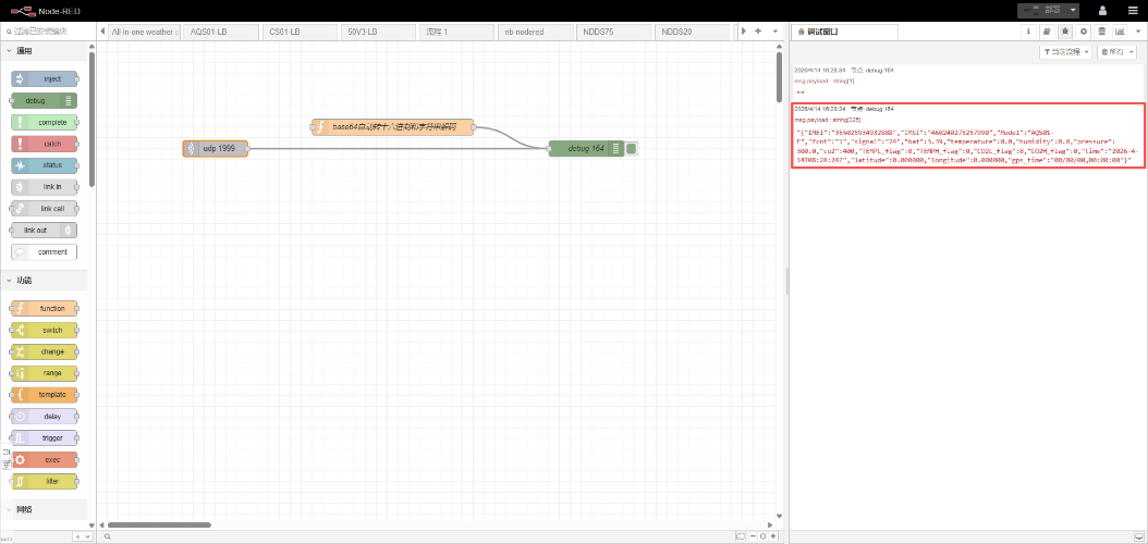
3.2 General MQTT Connection
The NB-IoT Sensor can send packet to server use MQTT protocol.
Below are the commands.
AT Commands:
- AT+PRO=3,0 // Set to use MQTT protocol to uplink, Payload Type select Hex payload.
- AT+SERVADDR=8.217.91.207,1883 // Set MQTT server address and port
- AT+CLIENT=CLIENT // Set up the CLIENT of MQTT
- AT+UNAME=UNAME // Set the username of MQTT
- AT+PWD=PWD // Set the password of MQTT
- AT+PUBTOPIC=SENSOR_PUB // Set the sending topic of MQTT
- AT+SUBTOPIC=SENSOR_SUB // Set the subscription topic of MQTT
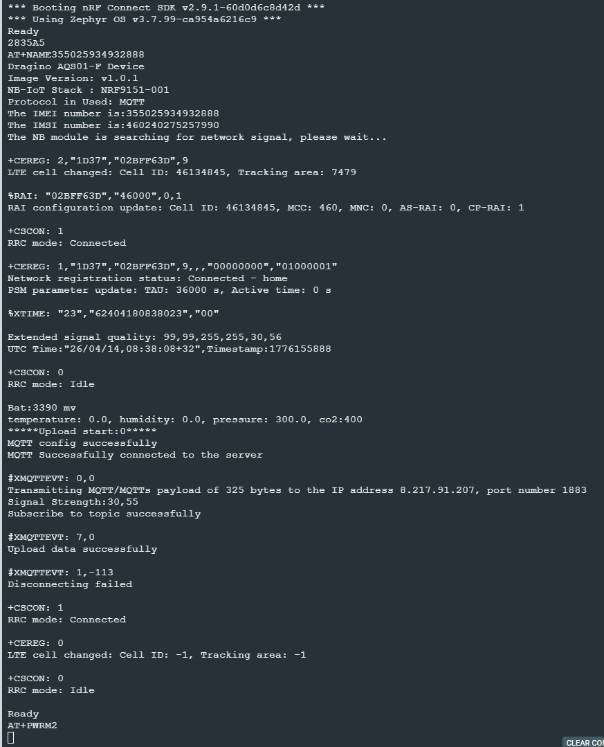
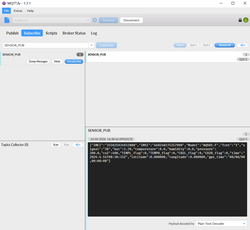
Notice: MQTT protocol has a much higher power consumption compare with UDP protocol. Please check the power analyze document and adjust the uplink period to a suitable interval.
3.3 Datacake
Dragino NB-IoT sensors has its template in Datacake Platform. There are two version for NB Sensor,
As example for S31B-FB. there are two versions: S31B-FB-1D and S31B-FB-GE.
- S31B-FB-1D: This version have pre-configure DataCake connection. User just need to Power on this device, it will auto connect send data to DataCake Server.
- S31B-FB-GE: This verson doesn't have pre-configure Datacake connection. User need to enter the AT Commands to connect to Datacake. See below for instruction.
3.3.1 For device Already has template
3.3.1.1 Create Device
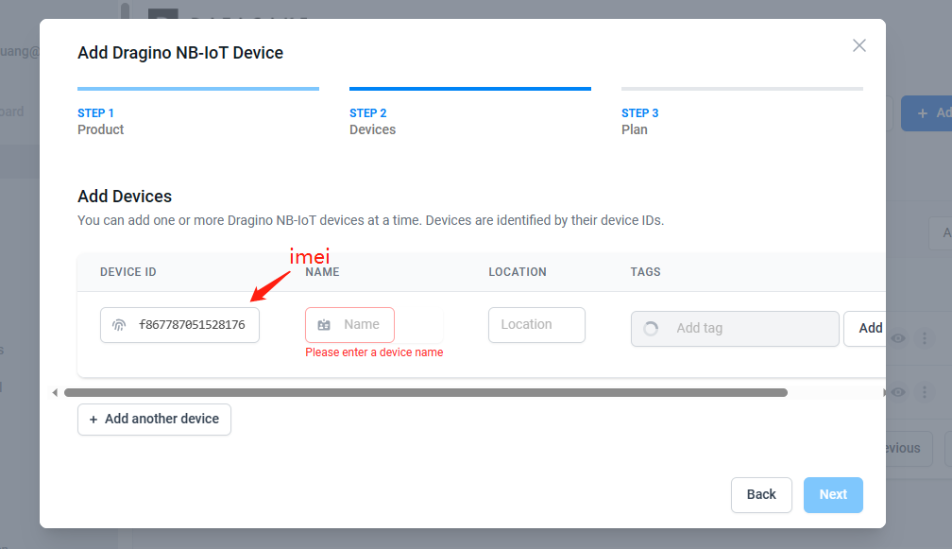
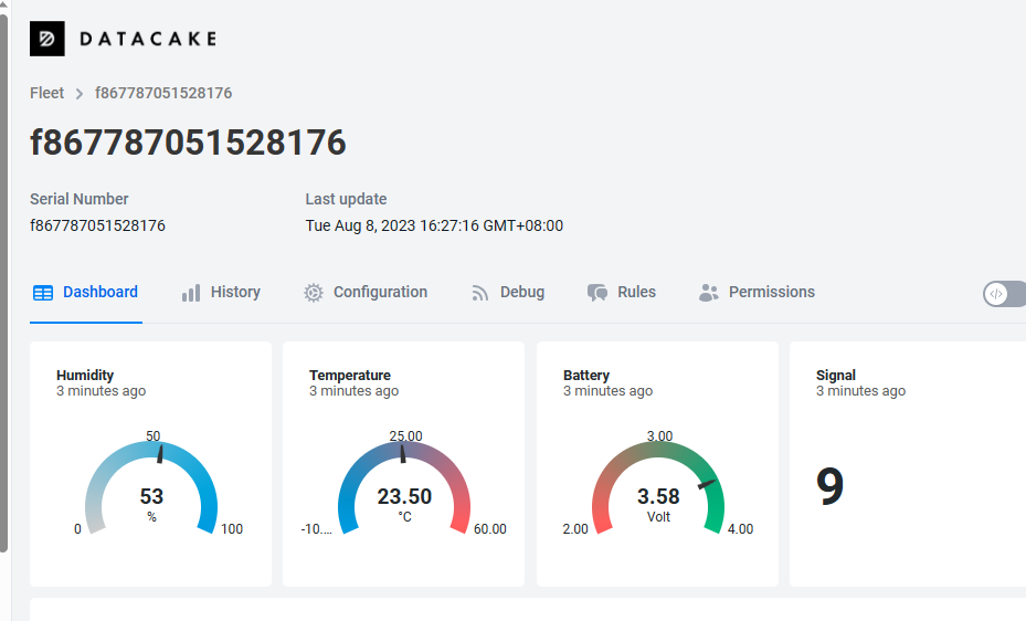
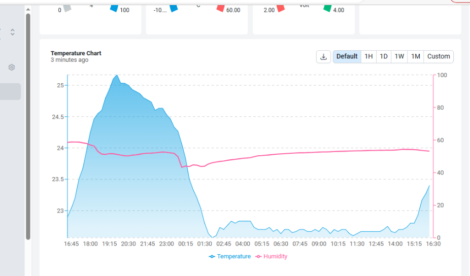
Add Device in DataCake.
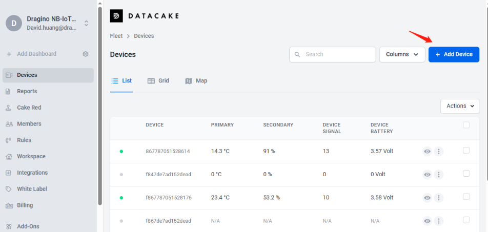
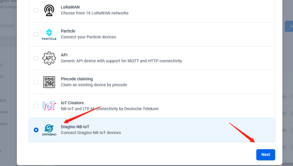
Choose the correct model from template.

Fill Device ID. The device ID needs to be filled in with IMEI, and a prefix of** 'f' **needs to be added.
3.3.2 For Device already registered in DataCake before shipped
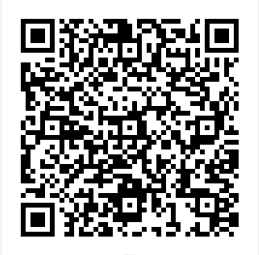
3.3.2.1 Scan QR Code to get the device info
Users can use their phones or computers to scan QR codes to obtain device data information.
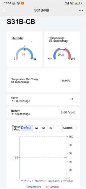
3.3.2.2 Claim Device to User Account
By Default, the device is registered in Dragino's DataCake Account. User can Claim it to his account.
3.3.3 Manual Add Decoder in DataCake ( don't use the template in DataCake)
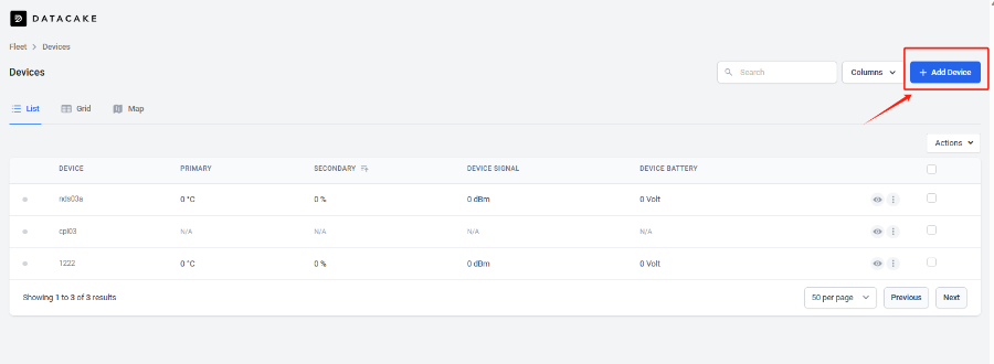
Step1: Add a device
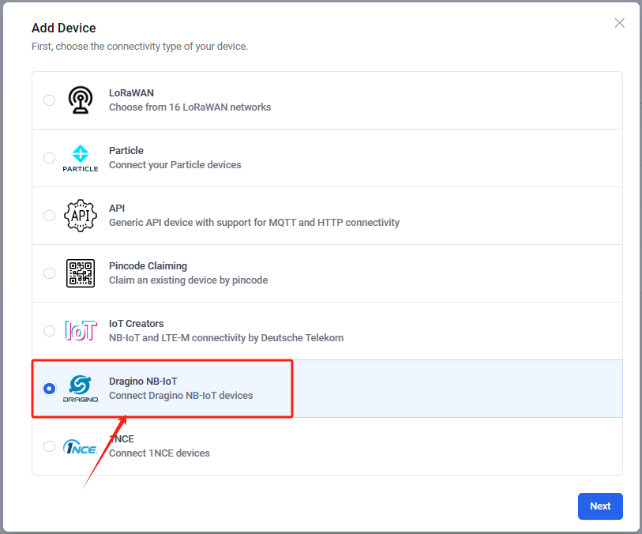
Step2: Choose your device type,please select dragino NB-IOT device
Step3: Choose to create a new device
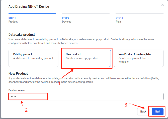
Step4: Fill in the device ID of your NB device
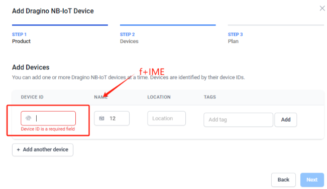
Step5: Please select your device plan according to your needs and complete the creation of the device

Step6: Please add the decoder at the payload decoder of the device configuration.Decoder location:dragino-end-node-decoder/Datacake-Dragino_NB at main · dragino/dragino-end-node-decoder (github.com)
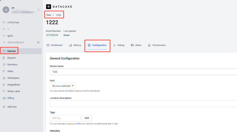
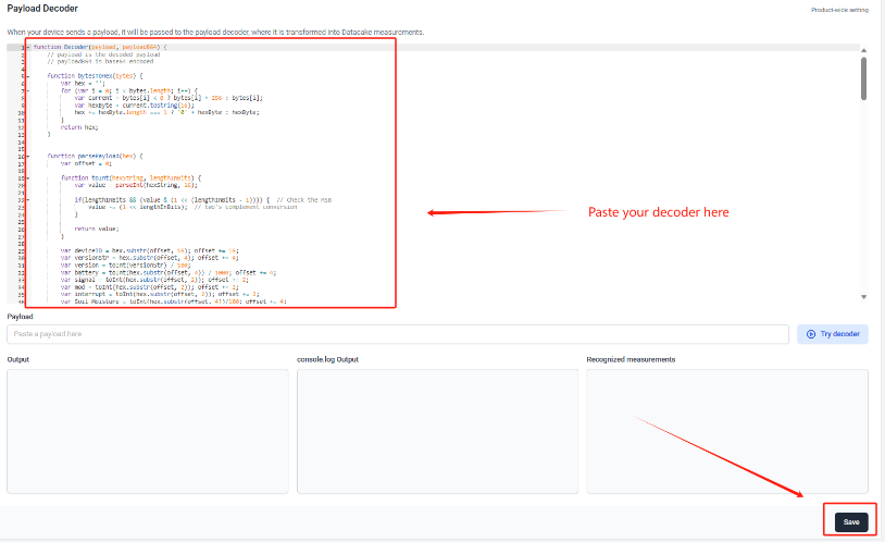
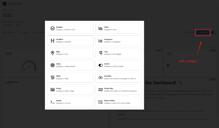
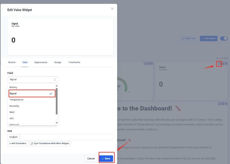
Step7: Add the output of the decoder as a field
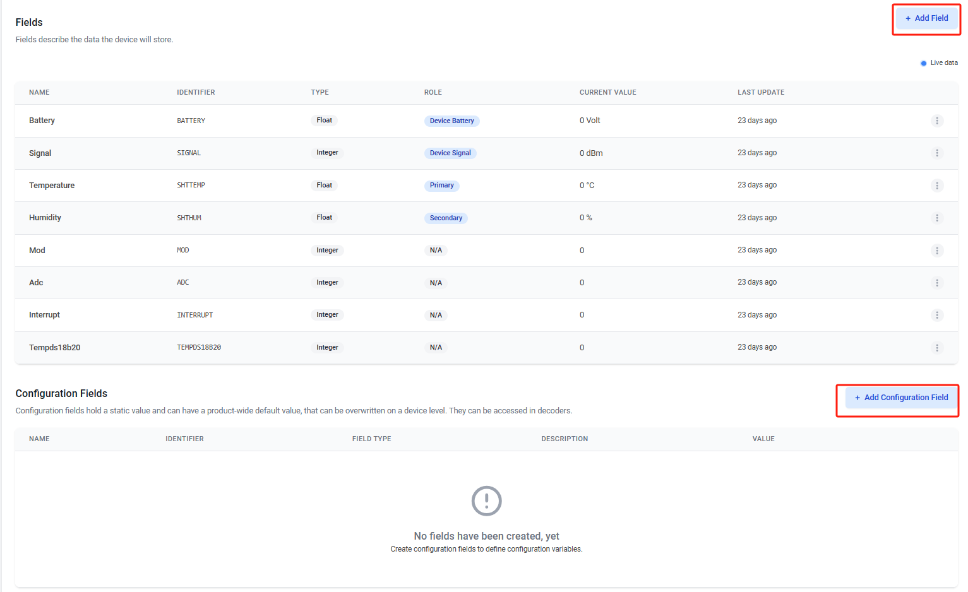
Step8: Customize the dashboard and use fields as parameters of the dashboard

3.3.4 For device have not configured to connect to DataCake
Use AT command for connecting to DataCake
AT+PRO=2,5AT+SERVADDR=67.207.76.90,4445
3.4 Node-Red (via MQTT)
3.4.1 Configure Node-Red
See Node-Red.
Take S31-NB UDP protocol as an example.
Dragino provides input flow examples for the sensors.
User can download the required JSON file through Dragino Node-RED input flow template.
Download sample JSON file link: https://www.dropbox.com/sh/mduw85jcuwsua22/AAAvwPhg9z6dLjJhmZjqBf_ma?dl=0
We can directly import the template.
The templates for S31-NB and NB95S31B are the same.
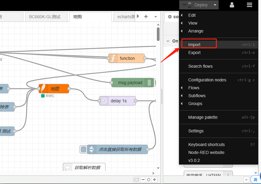
Please select the NB95S31B template.

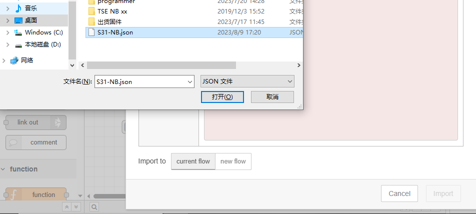
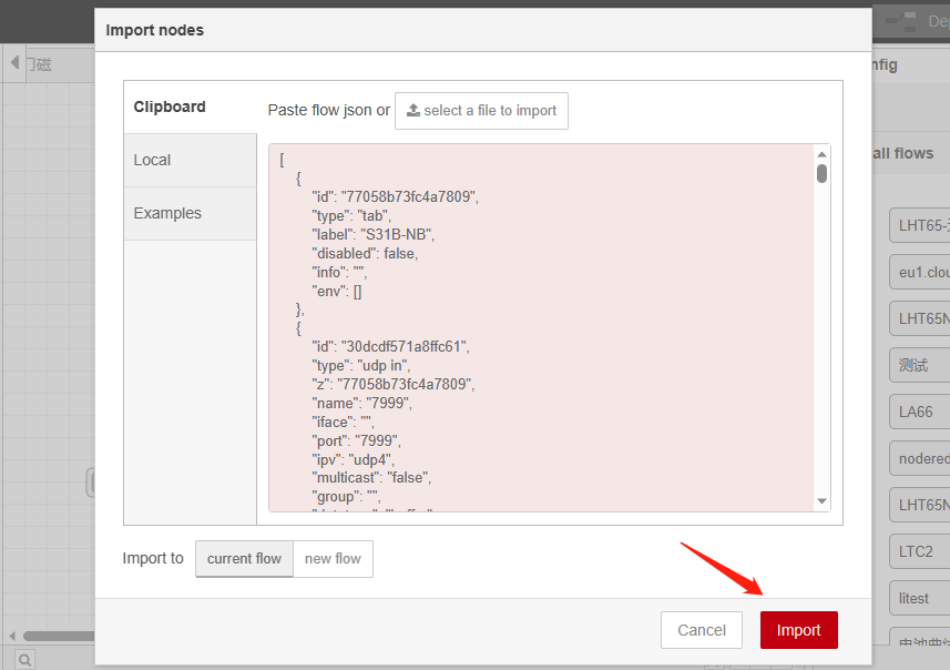
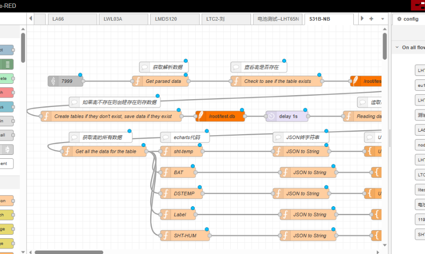
Successfully imported template.
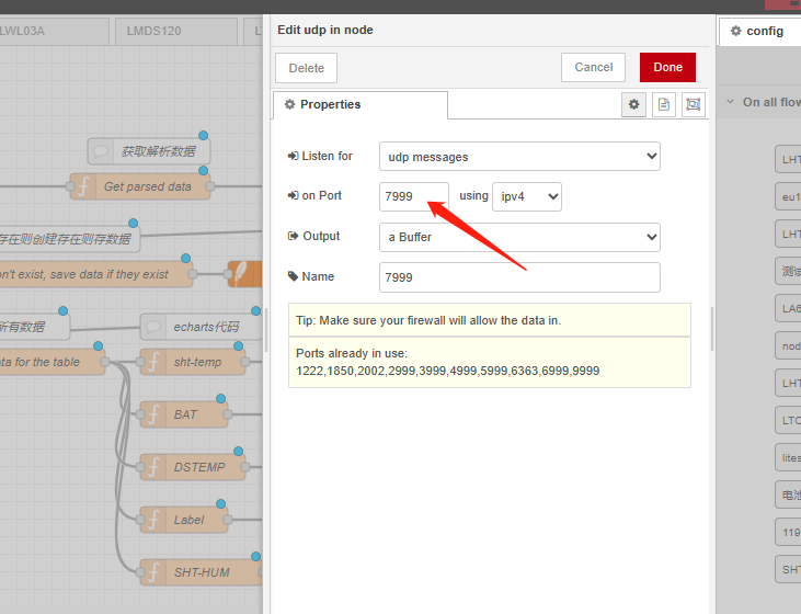
Users can set UDP port.
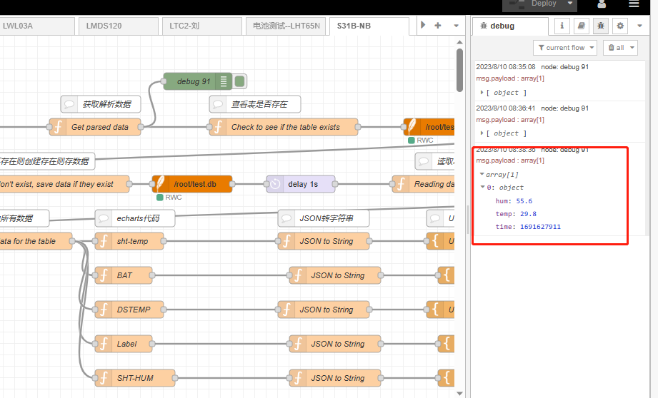
3.4.2 Simulate Connection
We have completed the configuration of UDP. We can try sending packets to node red.
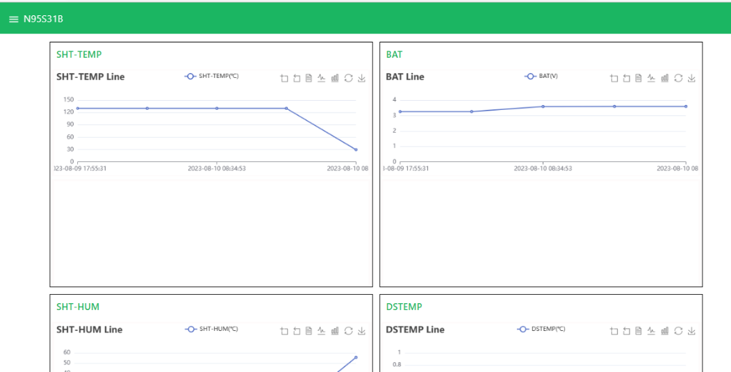
3.4.3 Configure NB-IoT Sensors
- AT+PRO=3,5 // json format
- AT+SUBTOPIC=
or User Defined - AT+PUBTOPIC=
or User Defined - AT+CLIENT=
or User Defined - AT+UNAME=
or User Defined - AT+PWD=“Your device token”
3.5 ThingsBoard.Cloud (via MQTT)
3.5.1 Configure ThingsBoard
3.5.1.1 Create Device
Create a New Device in ThingsBoard. Record Device Name which is used for MQTT connection.
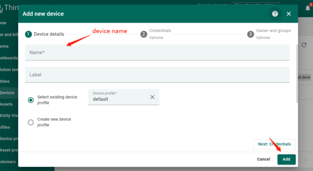
3.5.1.2 Create Uplink & Downlink Converter
Uplink Converter
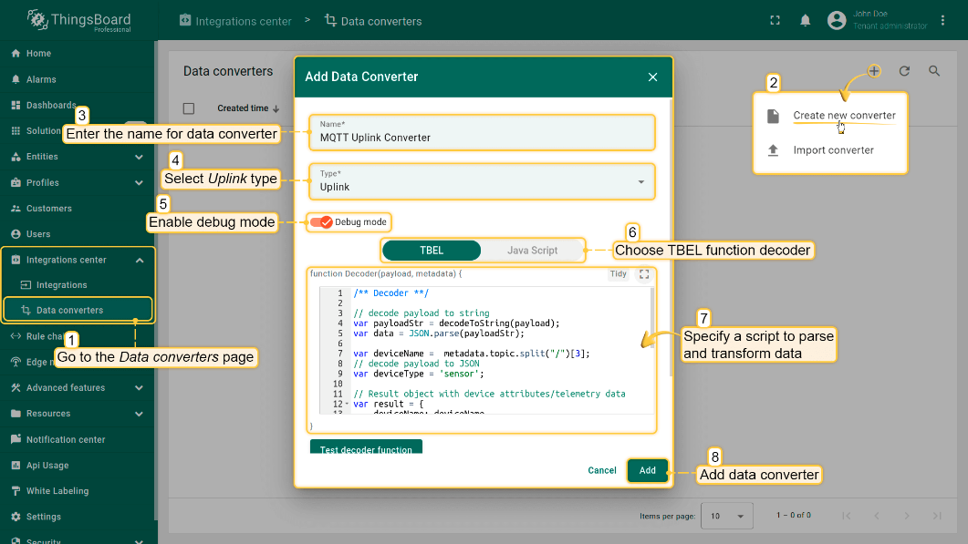
The purpose of the decoder function is to parse the incoming data and metadata to a format that ThingsBoard can consume. deviceName and deviceType are required, while attributes and telemetry are optional. Attributes and telemetry are flat key-value objects. Nested objects are not supported.
To create an uplink converter go to the Integrations center -> Data converters page and click “plus” button. Name it “MQTT Uplink Converter” and select type "Uplink". Use debug mode for now.
Downlink Converter
The Downlink converter transforming outgoing RPC message and then the Integration sends it to external MQTT broke
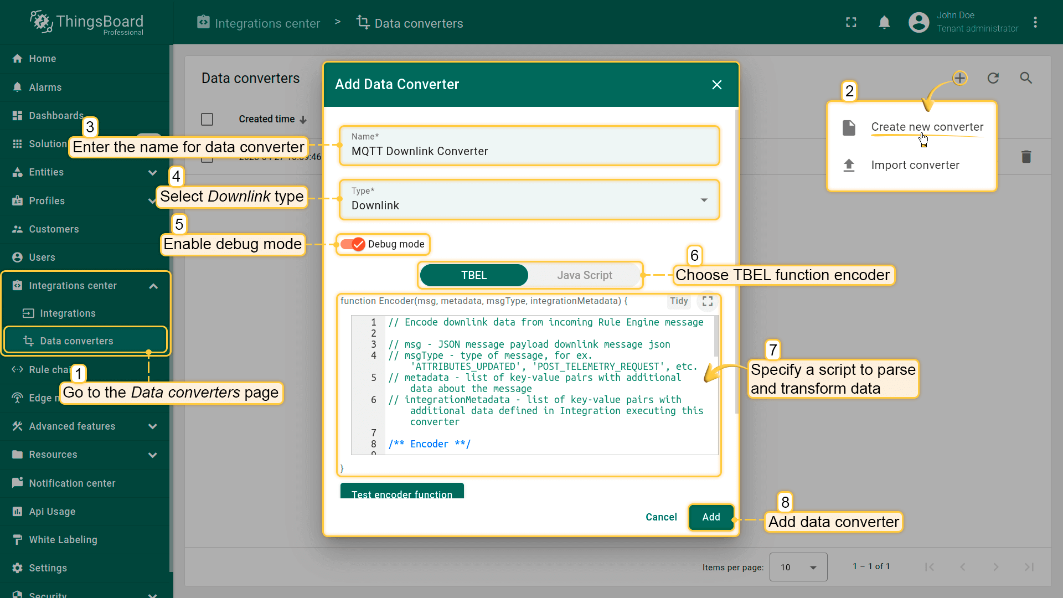
Note: Our device payload is already human readable data. Therefore, users do not need to write decoders. Simply create by default.
3.5.1.3 MQTT Integration Setup
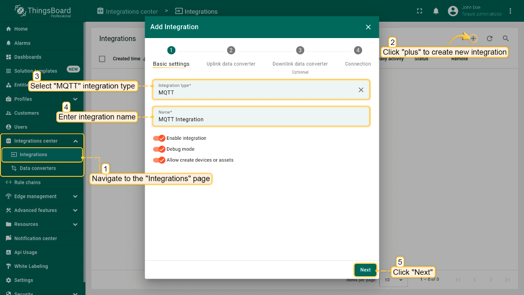
Go to the Integrations center->Integrations page and click “plus” icon to add a new integration. Name it “MQTT Integration”, select type MQTT;
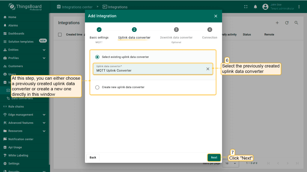
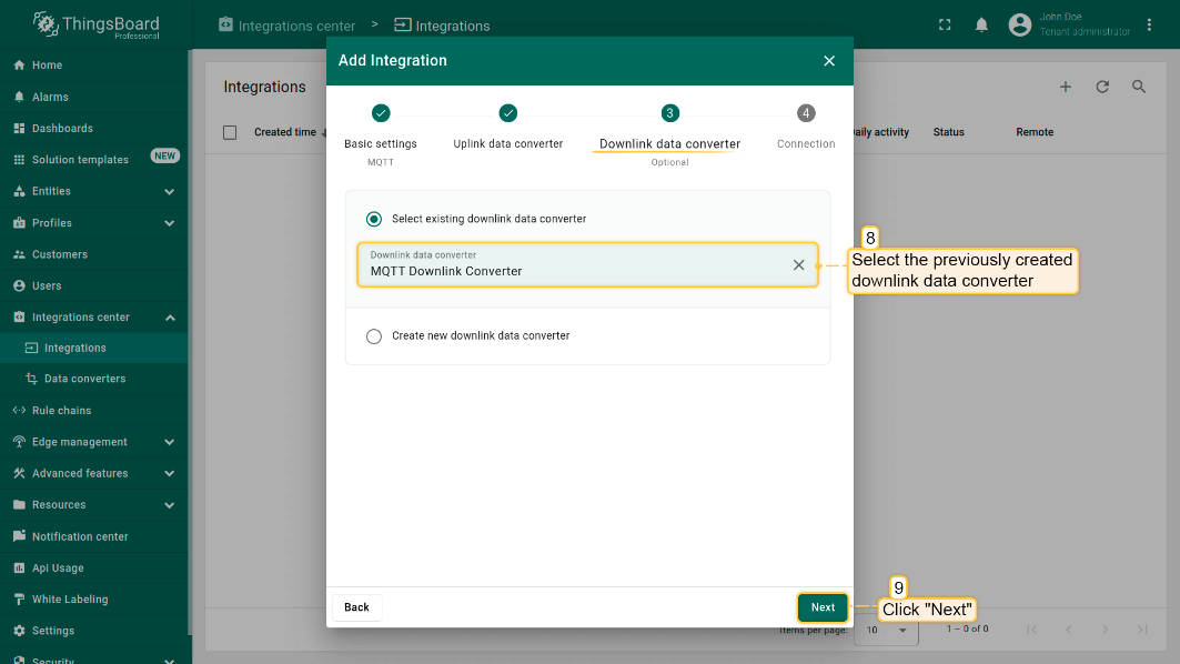
- The next steps is to add the recently created uplink and downlink converters;
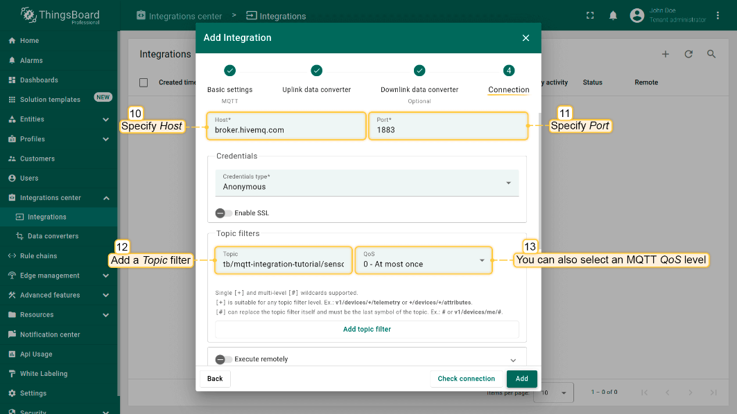
Add a topic filter:
Consistent with the theme of the node setting.
You can also select an MQTT QoS level. We use MQTT QoS level 0 (At most once) by default;
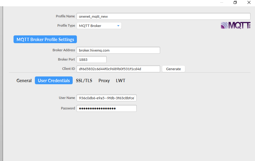
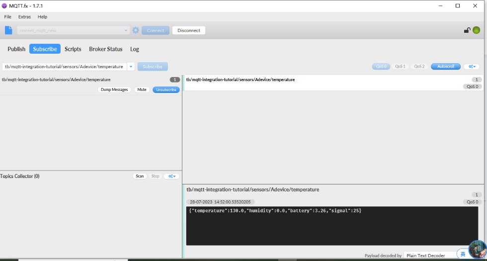
3.5.2 Simulate with MQTT.fx
3.5.3 Configure NB-IoT Sensor
AT Commands
- **AT+PRO=3,3 **// Use MQTT to connect to ThingsBoard. Payload Type set to 3.
- AT+SUBTOPIC=
- AT+PUBTOPIC=
- AT+CLIENT=
or User Defined
- AT+UNAME=
or User Defined
- AT+PWD=
or User Defined
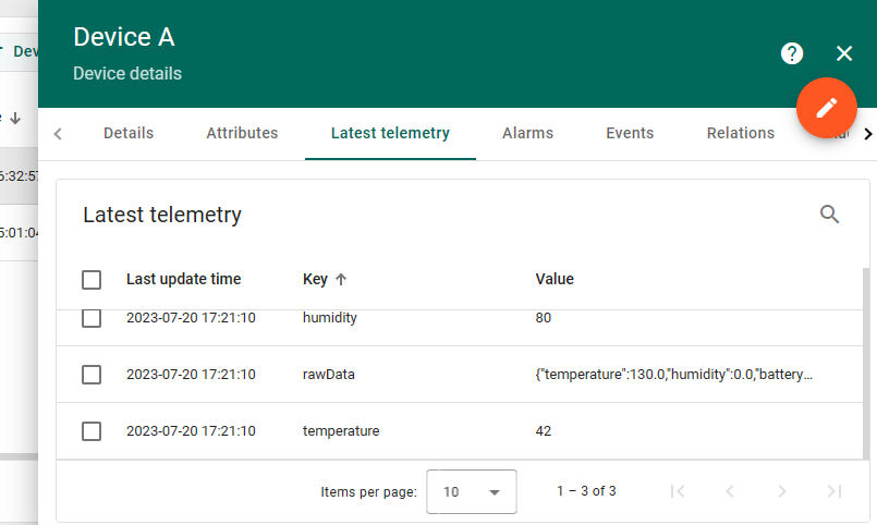
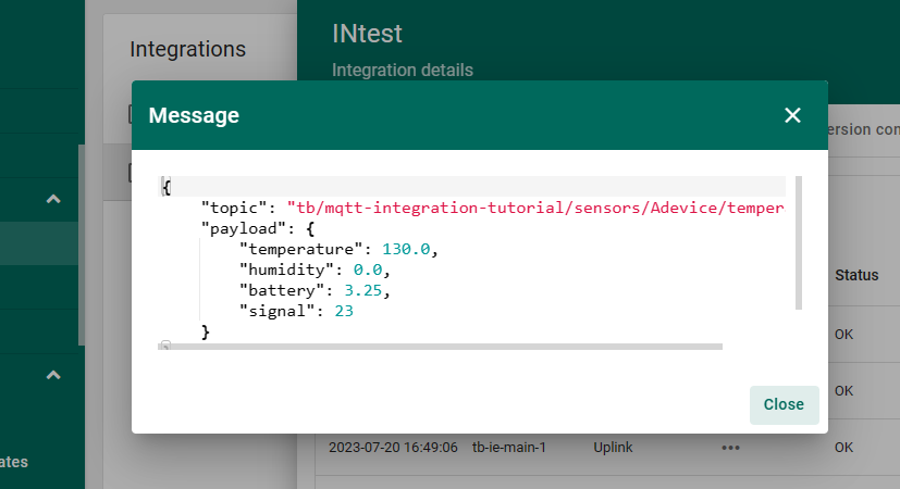
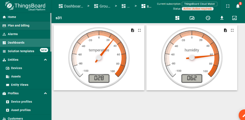
Test Uplink by click the button for 1 second
3.6 Tago.io (via MQTT)
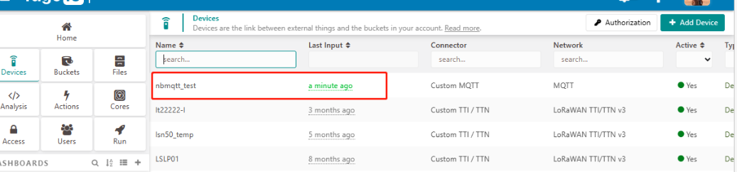
3.6.1 Create device & Get Credentials
We use MQTT Connection to send data to Tago.io. We need to Create Device and Get MQTT Credentials first.
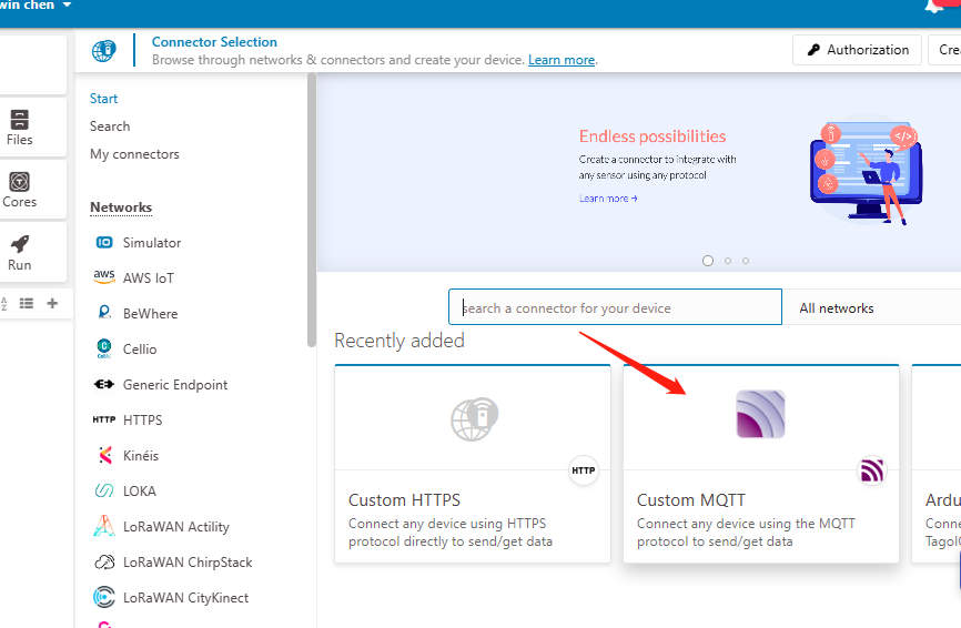
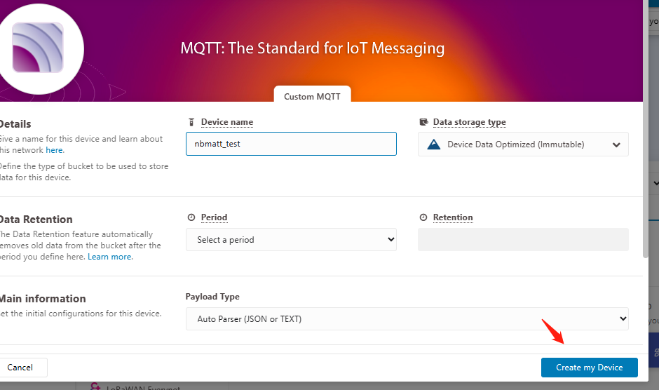
Go to the Device section and create a device. Then, go to the section tokens and copy your device-token.
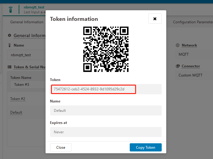
The device needs to enable the TLS mode and set the AT+TLSMOD=1,0 command.
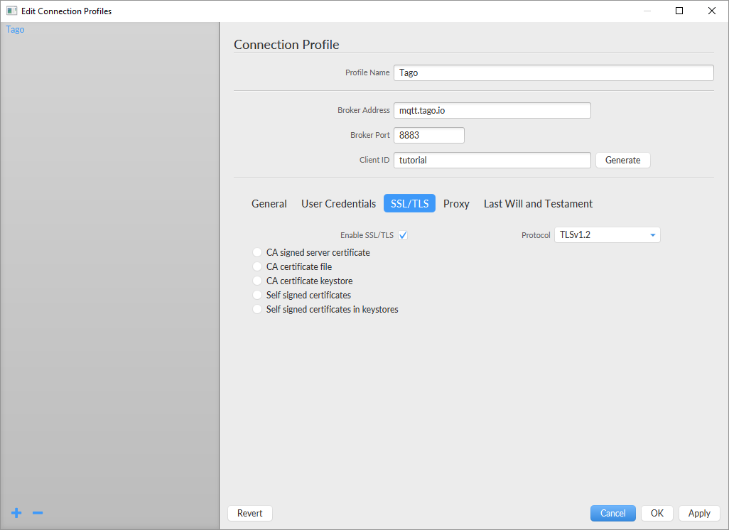
On the Connection Profile window, set the following information:
- Profile Name: “Any name”
- Broker Address: mqtt.tago.io
- Broker Port: 8883
-
Client ID: “Any value”On the section User credentials, set the following information:
-
User Name: “Any value”// Tago validates your user by the token only
- Password: “Your device token”
- PUBTOPIC: “Any value”
-
SUBTOPIC: “Any value”AT command:
-
AT+PRO=3,5 // hex format or json format
- AT+SUBTOPIC=
or User Defined
- AT+PUBTOPIC=
or User Defined
- AT+CLIENT=
or User Defined
- AT+UNAME=
or User Defined
- AT+PWD=“Your device token”
3.6.2 Simulate with MQTT.fx
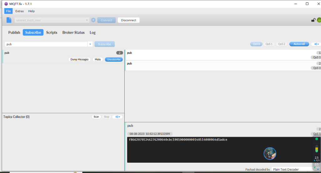
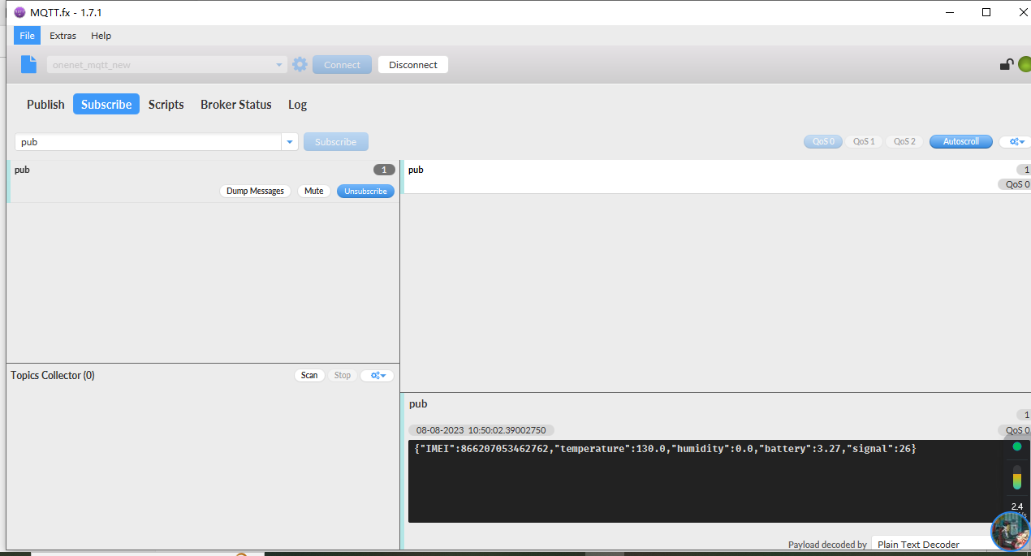
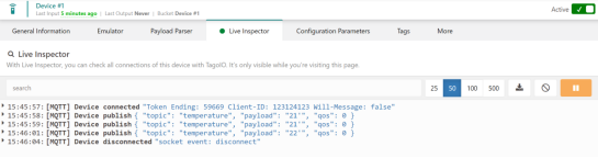
Users can run the AT+PRO=3,5 command, and the payload will be converted to JSON format.
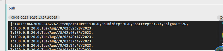
3.6.3 tago data
3.7 TCP Connection
AT command:
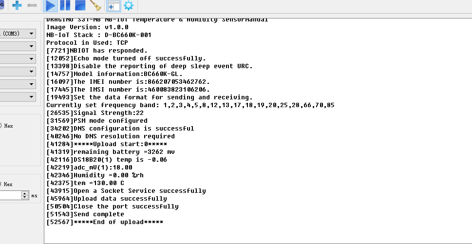
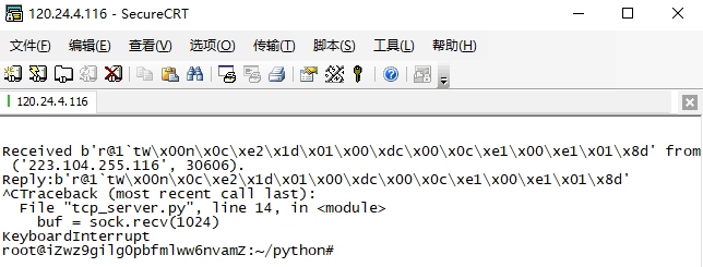
- **AT+PRO=4,0 ** // Set to use TCP protocol to uplink(HEX format)
- **AT+SERVADDR=8.217.91.207,5600 ** // to set TCP server address and port
Sensor Console Output when Uplink:
See result in TCP Server:
3.8 AWS Connection
Users can refer to Dragino NB device connection to AWS platform instructions
3.9 ThingsEye (via MQTT)
3.9.1 Configure ThingsEye
3.9.1.1 Create MQTT integration
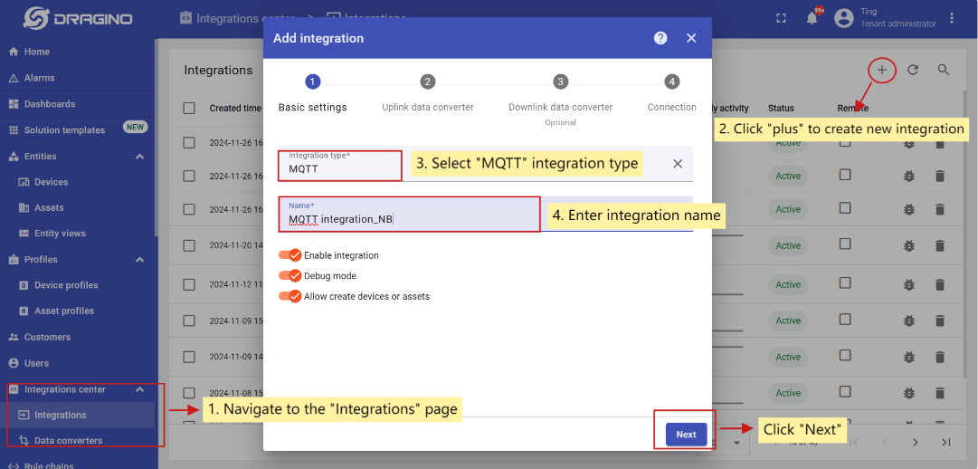
Go to the Integrations center->Integrations page and click “plus” icon to add a new integration. Name it “MQTT Integration_NB”, select type MQTT;
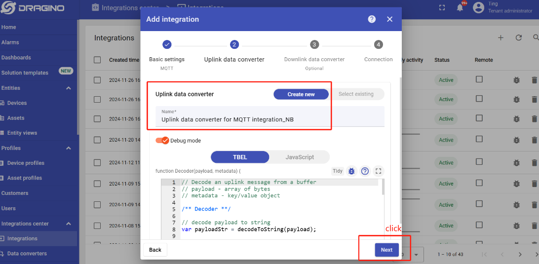
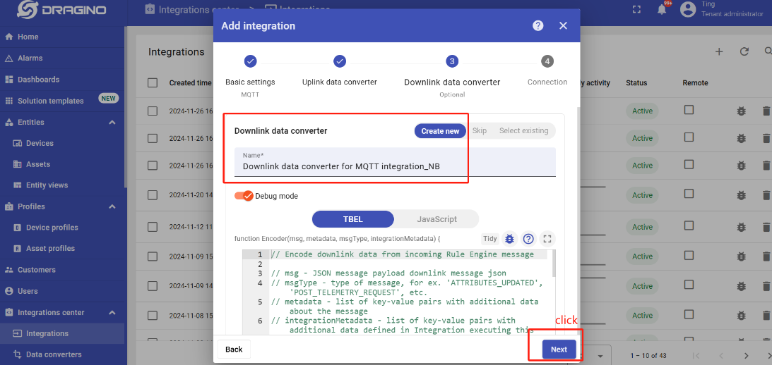
Next, directly select to create a new Uplink data converter and downlink data converter.
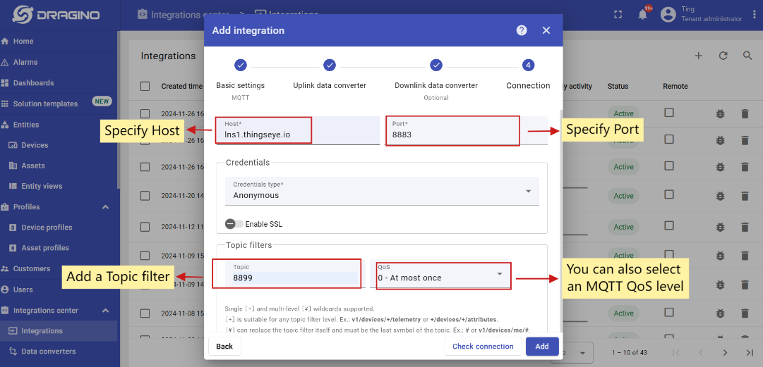
Add a topic filter:
Consistent with the theme of the node setting.
Note: Recommended MQTT broker: lns1.thingseye.io 8883, fixed use. Topic can be changed on their own, but it need to be consistent with the node's publish and subscribe topic.
You can also select an MQTT QoS level. We use MQTT QoS level 0 (At most once) by default;
3.9.1.2 Add credentials to the MQTT integration
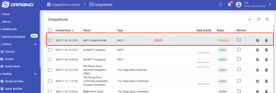
Click on the MQTT integration you just created.
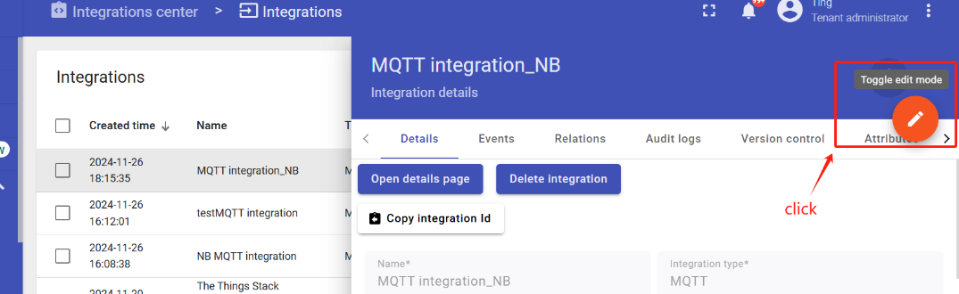
Click the edit icon in the upper right corner to enter the edit mode.
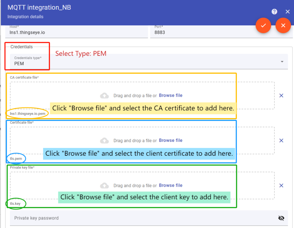
Add credential files.
Click this link to download the certificates.
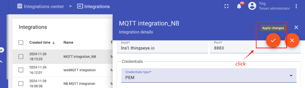
When the addition is complete, save the Settings.

3.9.1.3 Setup uplink and downlink converters
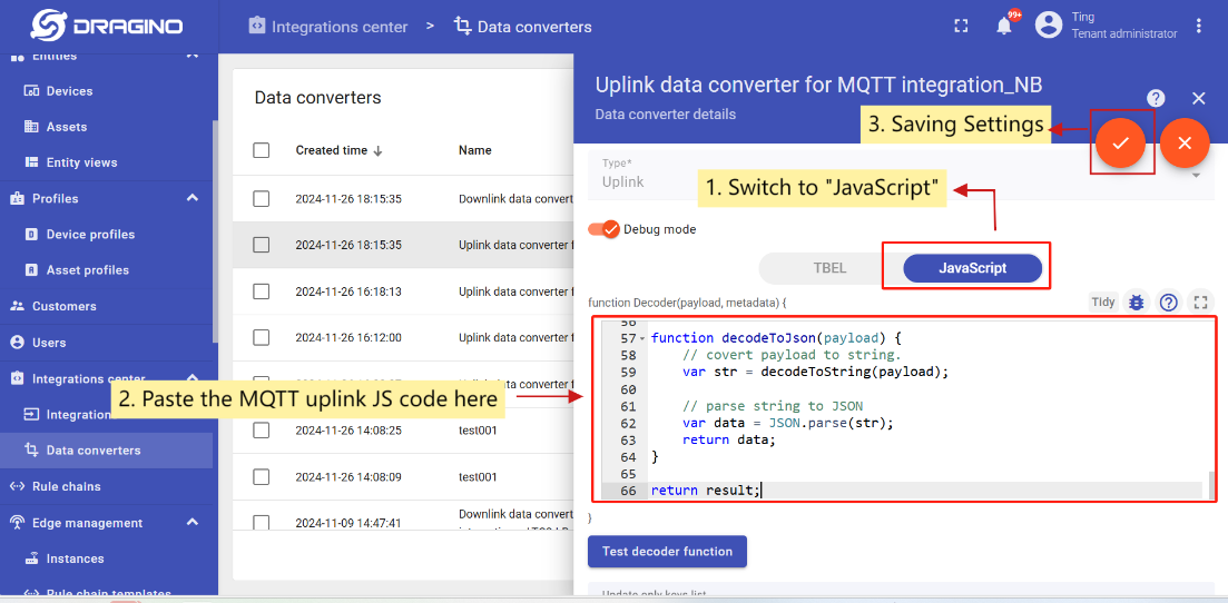
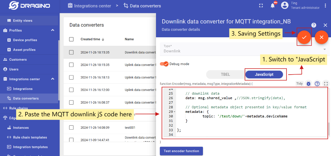
First, you need to download the MQTT uplink/downlink JScode.
- Uplink Converter
The purpose of the decoder function is to parse the incoming data and metadata to a format that ThingsBoard can consume.
Go to the Integrations center -> Data converters page, and find that MQTT uplink converter that was newly created when the integration was created.
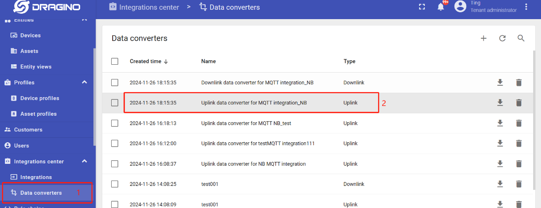
Enter edit mode and apply MQTT uplink JS code to this uplink converter.
- Downlink Converter
Go to the Integrations center -> Data converters page, and find that MQTT downlink converter that was newly created when the integration was created.
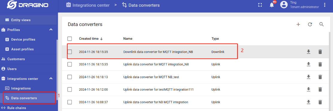
Enter edit mode and apply MQTT downlink JS code to this downlink converter.
3.9.2 Simulate with MQTT.fx
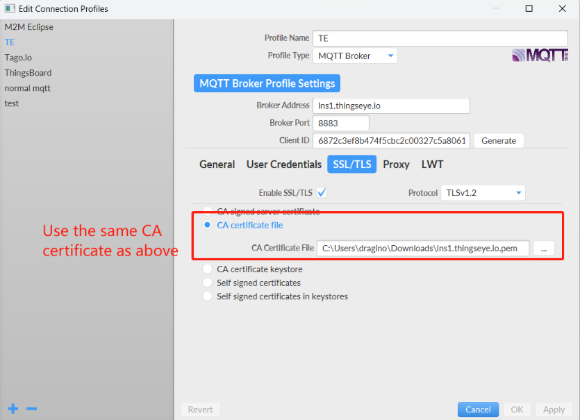
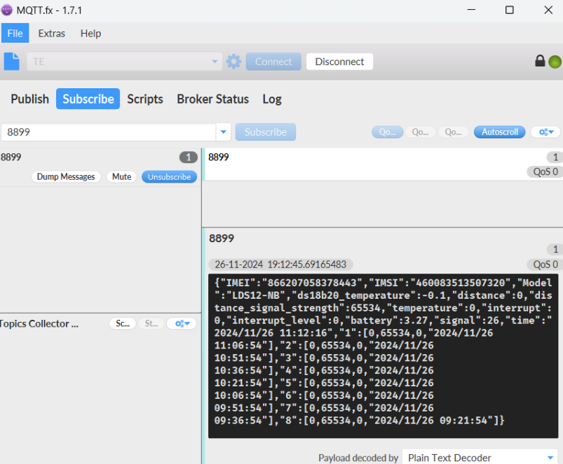
3.9.3 Configure -FB Node: Write Certificates
This section explains how to write CA certificate, client certificate, and client private key to the -FB series device (Nordic nRF9151) for TLS authentication.
Enter Certificate Writing Mode:
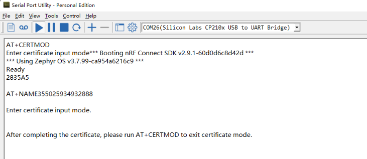
Exit Certificate Writing Mode:
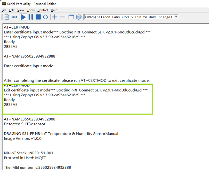
Note: After exiting certificate writing mode, the device will automatically restart.
3.9.3.1 AT%CMNG Command Explanation
Feature: Manage certificates on -FB/-FS series devices (Nordic nRF9151). Supports writing, listing, reading, and deleting certificates.
AT command: AT%CMNG=
| Command Format/Example | Function/Parameters | Description |
|---|---|---|
| AT%CMNG=1 | List all certificates | Displays all stored certificates with sec_tag and type |
| AT%CMNG=3,<sec_tag>, | Delete a certificate | Deletes the specified certificate |
Parameter Description:
- opcode - Operation type:
- 0 - Write a certificate
- 1 - List all certificates
- 2 - Read a specific certificate
- 3 - Delete a certificate
- sec_tag - Security tag. Use the same tag for CA, Client, and Private Key (e.g., 24).
- type - Certificate type:
- 0 - Root CA certificate
- 1 - Client certificate
- 2 - Client private key
- 3 - PSK (Pre-Shared Key)
- 4 - PSK identity
- 5 - Public key
- content - Actual certificate/key content in PEM format (including BEGIN/END lines)
**Example: **
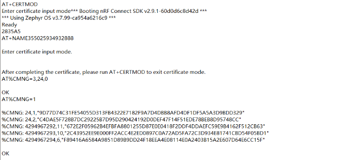
- **AT%CMNG=1 ** //List all certificates
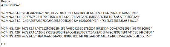
- AT%CMNG=3,24,0 //Delete CA certificate
3.9.3.2 Write CA Certificate
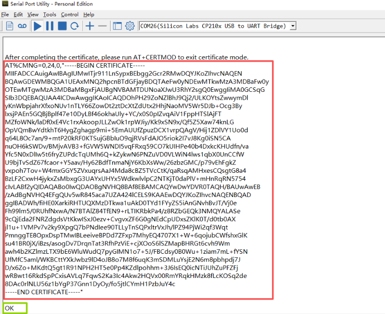
Feature: Write root CA certificate to the device.
AT command: AT%CMNG=0,24,0,"<ca_certificate_content>"Example: Replace <ca_certificate_content> with the actual CA certificate in PEM format.
3.9.3.3 Write Client Certificate
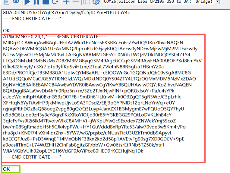
Feature: Write client certificate to the device.
AT command: AT%CMNG=0,24,1,"<client_certificate_content>"Example: Replace <client_certificate_content> with the actual client certificate in PEM format.
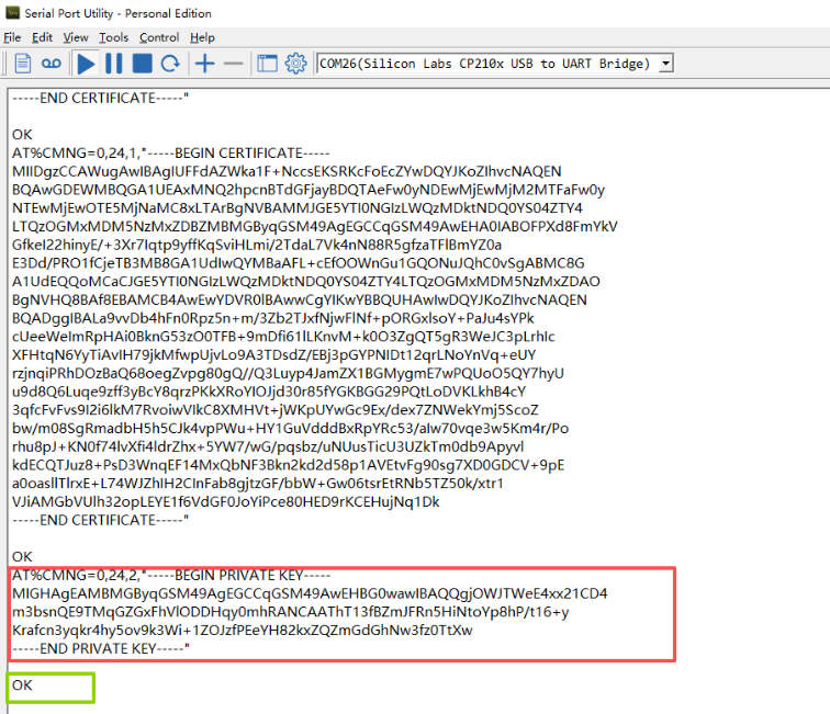
3.9.3.4 Write Client Private Key
Feature: Write client private key to the device.
AT command: AT%CMNG=0,24,2,"<private_key_content>"Example: Replace <private_key_content> with the actual client private key in PEM format.
3.9.3.5 Delete Certificates
Feature: Delete existing certificates from the device.
AT command: AT%CMNG=3,<sec_tag>,
| Command Example | Function |
|---|---|
| AT%CMNG=3,24,0 | Delete CA certificate (type=0) |
| AT%CMNG=3,24,1 | Delete client certificate (type=1) |
| AT%CMNG=3,24,2 | Delete private key (type=2) |
3.9.3.6 Configure MQTT Connection to ThingsEye
After certificates are written, configure the -FB node to connect to ThingsEye platform using TLS:
AT Commands
- **AT+PRO=3,5 **// Use MQTT Connection & Json Payload
- **AT+SERVADDR=lns1.thingseye.io,8883 **
- **AT+SUBTOPIC=8899 **// Consistent with the Topic of MQTT integration created by ThingsEye
- **AT+PUBTOPIC=8899 **// Consistent with the Topic of MQTT integration created by ThingsEye
- AT+CLIENT=NULL
- AT+UNAME=NULL
- AT+PWD=NULL
- AT+TLSMOD=1,2
Press the ACT button for 1-3 seconds. The device should now send data securely to ThingsEye.
3.10 ThingsEye (via UDP)
3.10.1 Configure ThingsEye
Note:1. Since platform configuration involves port data forwarding, it will be handled by platform technicians.2. Users only need to configure their NB devices and provide the NB device's “IMEI” to the platform technicians for port data forwarding to the corresponding user account.
3.10.2 Device Configuration
AT Commands
- **AT+PRO=2,5 **// Use UDP Connection & Json Payload
- **AT+SERVADDR=server1.thingseye.io,11560 **// Configure the UDP server domain name and port
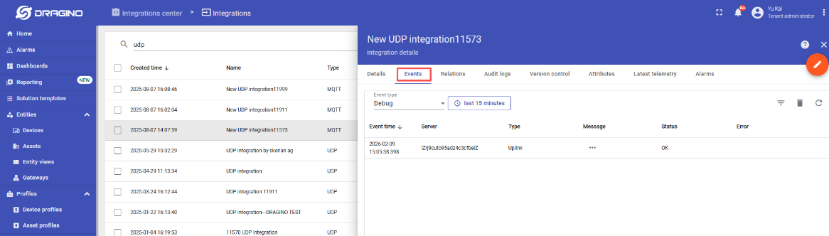
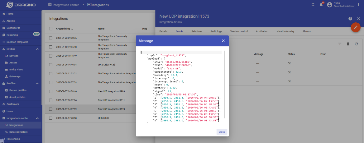
Click the button for 1–3 seconds to test the uplink. ThingsEye's UDP integration feature allows you to view your device's upstream data.
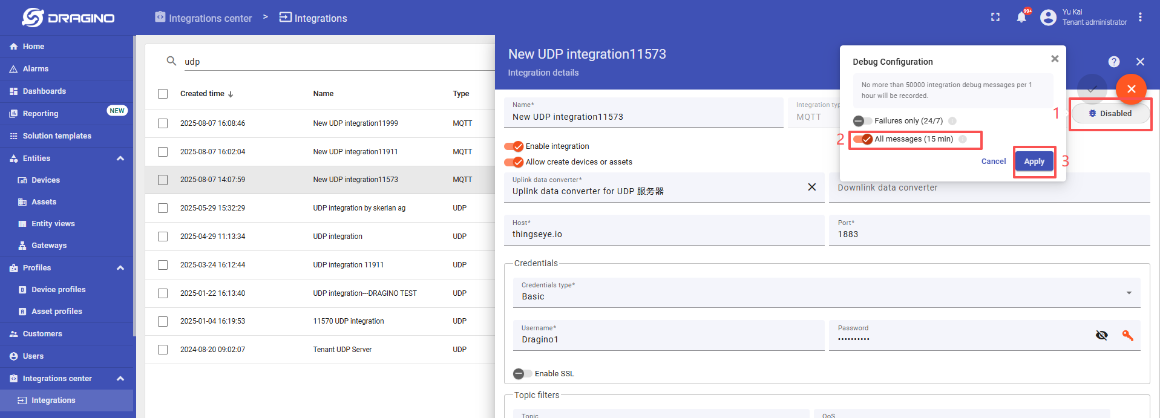
Note: Requires enabling the Debug Receive Data function within the UDP integration feature, which is disabled by default.
Select the corresponding UDP integration -> Click to enter the UDP integration configuration interface -> Click the button in the upper-right corner to enter edit mode -> Click "Debug mode" -> Open "All messages (15 min)" -> Click "Apply" to save
:
Test Uplink by click the button for 1~3 seconds, the UDP integration in ThingsEye allows you to view the data upstream from the device:
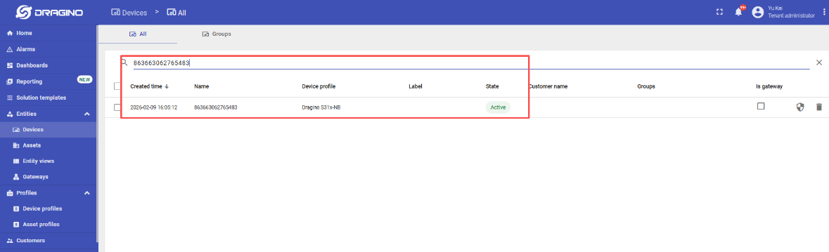
Go to "Device" ** -> ** "Search Device", enter the ** IMEI** of the device to find the device.
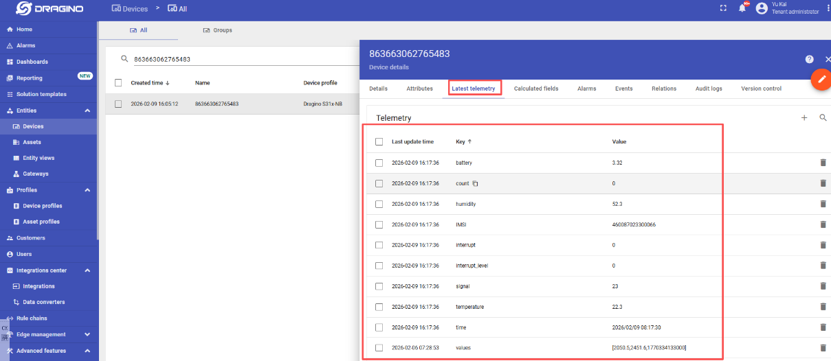
You can view the data that has just been uplink on the device:
4. UDP/MQTT/TCP Downlink
4.1 MQTT (via MQTT.fx)
Configure MQTT connections properly and send downlink commands to configure nodes through the Publish function of MQTT.fx*.*
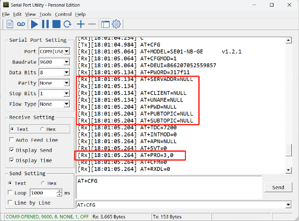
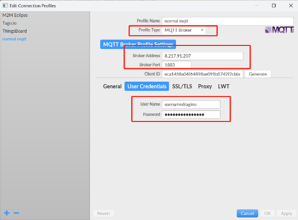
1. Configure node MQTT connection (via MQTT.fx):
AT command:
- **AT+PRO=3,0 or 3,5 ** // hex format or json format
- AT+SUBTOPIC=User Defined
- AT+PUBTOPIC=User Defined
- AT+UNAME=
or User Defined
- AT+PWD=
or User Defined
- **AT+SERVADDR=8.217.91.207,1883 ** // to set MQTT server address and port
Note: To uplink and downlink via MQTT.fx, we need set the publish topic and subscribe topic different, for example: AT+SUBTOPIC=SE01_SUB & AT+PUBTOPIC=SE01_PUB.
**2. **When the node uplink packets, we can observe the data in MQTT.fx.
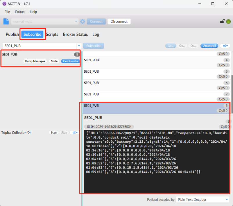
**3. **The downlink command can be successfully sent only when the downlink port is open.
The downlink port is opened for about 3 seconds after uplink packets are sent.

Therefore, when we see the node uplink packets in the **Subscribe** window, we need to immediately switch to the **publish** window to publish the **hex format** command.
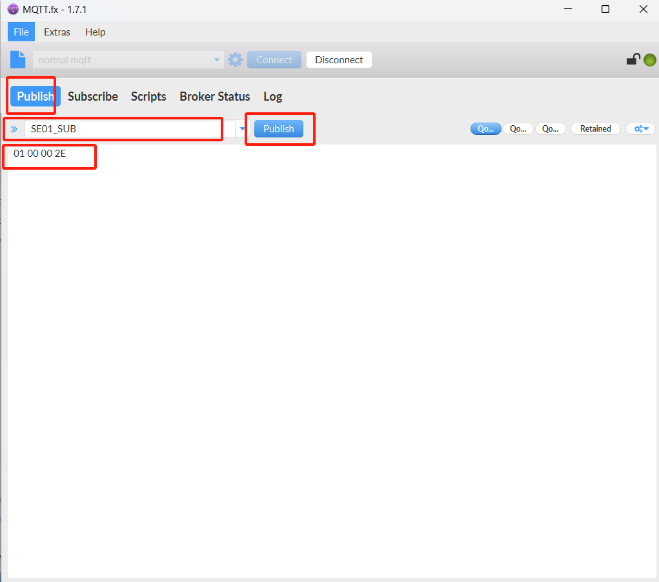
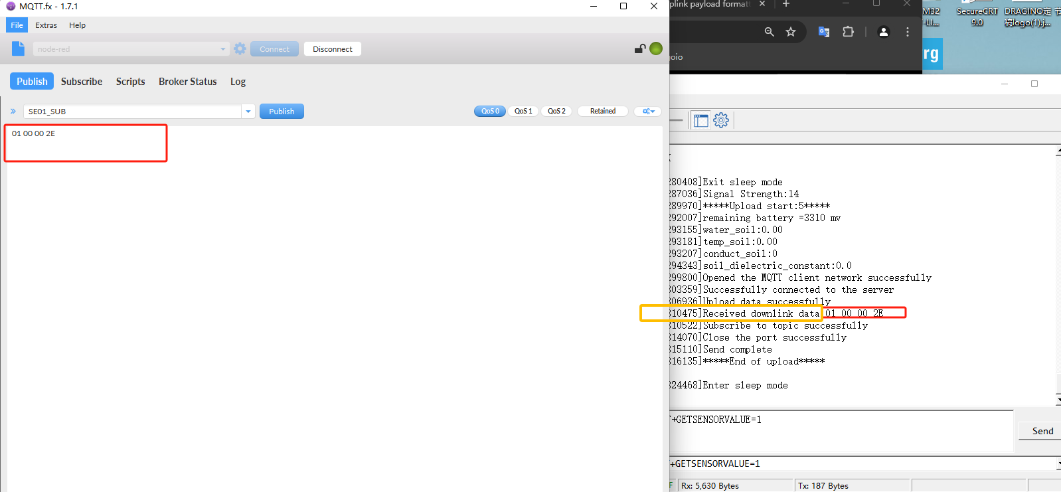
Note: Users can edit the hex command in advance. When the node uplink, directly click the publish button several times to increase the success rate of command configuration.
4.2 UDP (via Thingseye)
Note: The UDP service on the ThingsEye platform needs to be built by the user. (Description Link:UDP service building instructions)
After the node is successfully connected to the platform, you need to select the corresponding node (you can refer to the node's IMEI to find it)
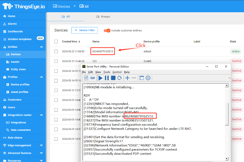
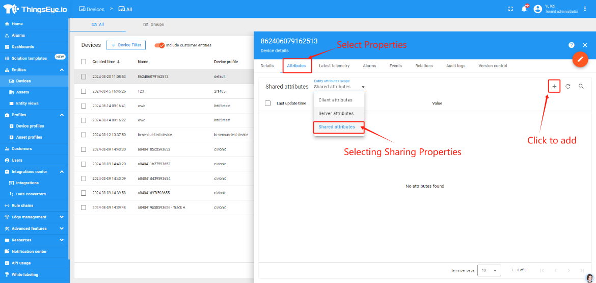
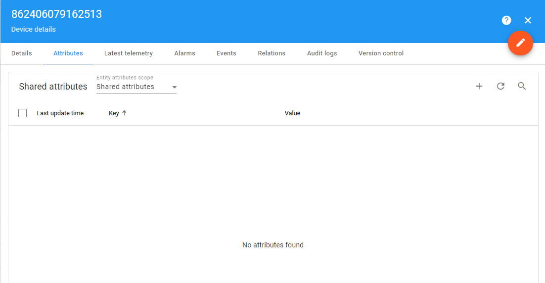
After clicking Show Node Details Page, Select Properties --- select Shared Properties --- click Add Properties
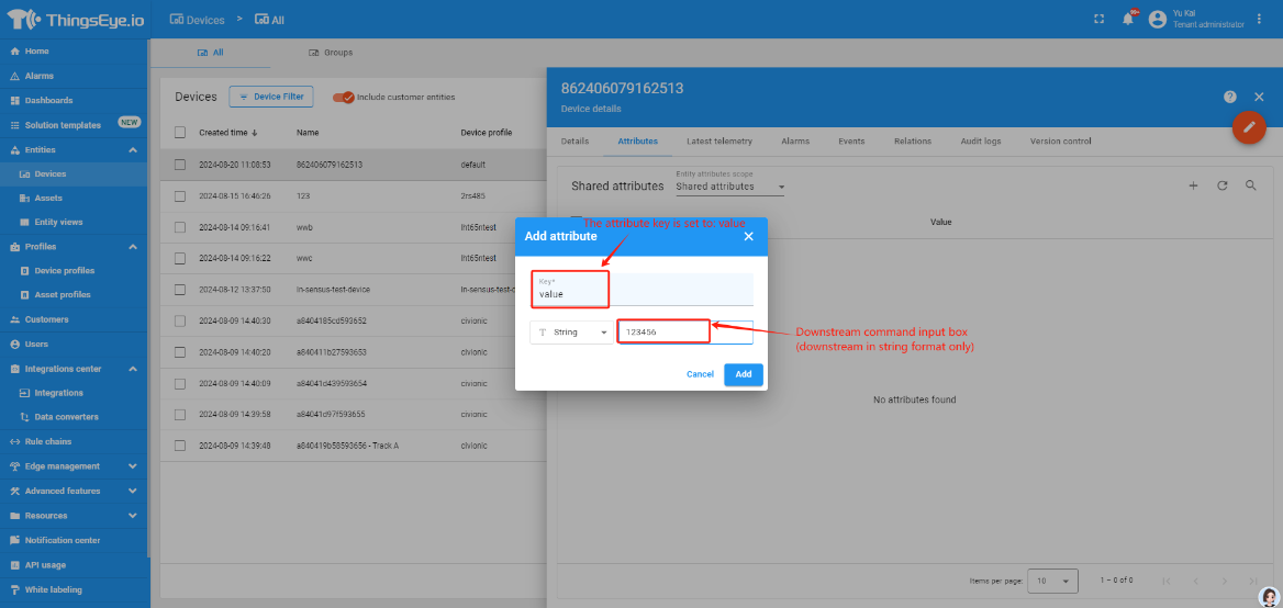
After clicking Add Shared Attribute, set the key to value, and write the command that needs to be downlinked in the Downlink Command Input box
(Note: Downlinks can only be downlinked in string format, otherwise the node will not recognize the downlink command.)
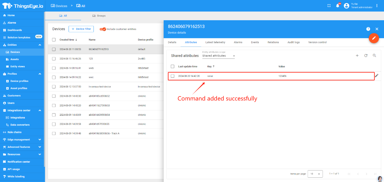
After the command is successfully added, the platform will send the command down on the node's next uplink.
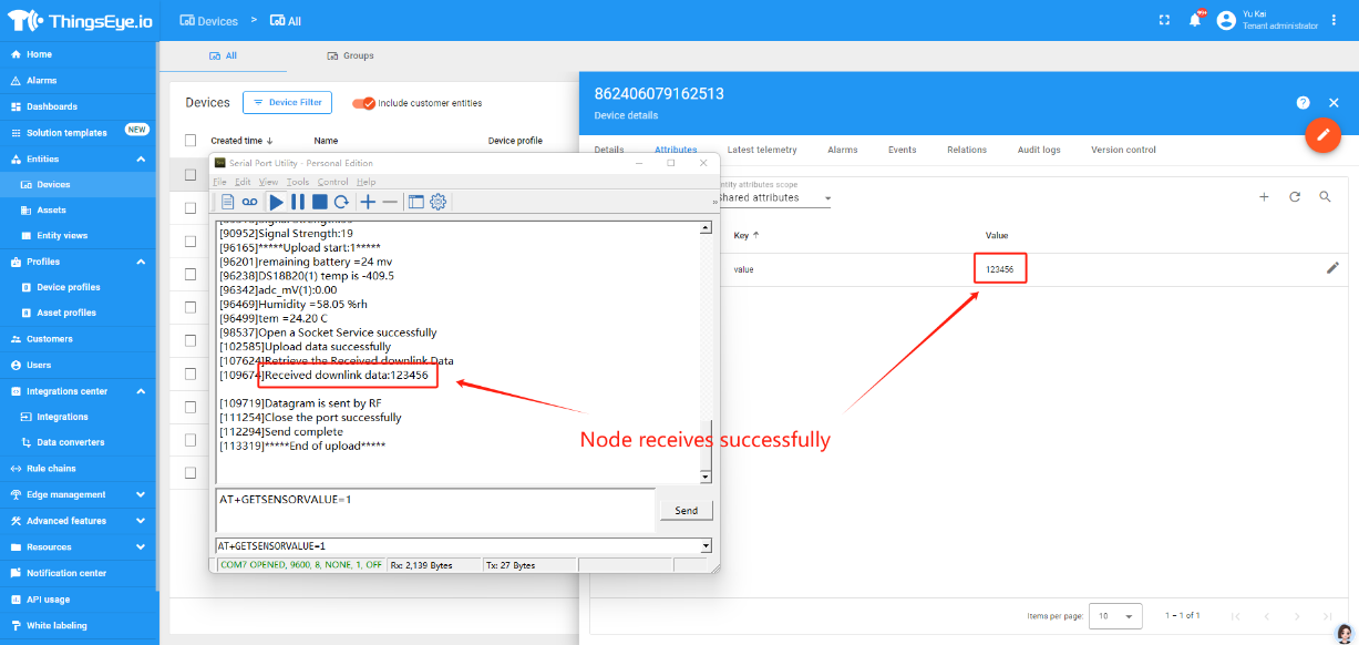
Upon successful issuance, the platform automatically eliminates the attributes from the queue and waits for the next addition of new attributes
5. GPS positioning function
1. Turn on GPS function
AT+QGPS=1 or 0 // GPS function on or off
2. Extend the time to turn on GTIME
AT+GTIME=30 // GPS search for positioning information for 30 seconds
3. Get or set GPS positioning interval in units of hour
AT+QGTDC=24 // The device will activate GPS positioning every 24 hours
6. FAQ
6.1 How to Update the firmware on the NRF9151-NGFF Module?
To update the firmware , please follow the instructions at this link: Firmware Update Guide
6.2 Downlink Command Format for FB Devices
6.2.1 JSON Downlink Format Specification
{"Config":"[ATcommand1;ATcommand2;...ATcommandX]"}
- Config: Fixed key indicating a configuration command sequence.
- Value: A string containing AT commands separated by semicolons (;) within square brackets.
Examples:
① Basic Configuration
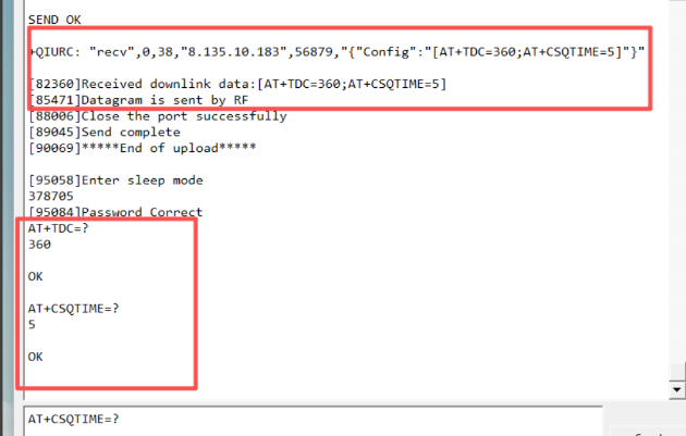
For settings that take effect immediately (e.g., updating reporting intervals): {"Config":"[AT+TDC=360;AT+CSQTIME=5]"}
// This sets the periodic uplink interval (AT+TDC) to 360 seconds and the signal search attempt duration (AT+CSQTIME) to 5 minutes.
② Configuration Requiring Device Reset
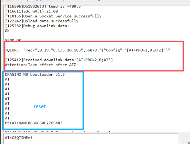
For commands that require a device restart to apply (e.g., changing the server address or protocol), you must append the reset command ATZ at the end: {"Config":"[AT+SERVADDR=xxx.xxx.xxx.xxx,yyyy;ATZ]"}{"Config":"[AT+PRO=2,0;ATZ]"}
//The ATZ command ensures the device reboots and the new settings take effect.
6.2.2 Important Notes on HEX Command Format
Standard HEX Downlink
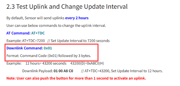
When sending individual AT commands in their HEX-encoded format (as defined in the command reference), send them directly as a single HEX string.
Example:
AT+TDC=300 corresponds to 0100012C Send: 0100012C
7. Trouble Shooting:
7.1 Checklist for debuging Network Connection issue. Signal Strenght:99 issue.
There are many different providers provide NB-IoT service in the world. They might use different band, different APN & different operator configuration. Which makes connection to NB-IoT network is complicate.
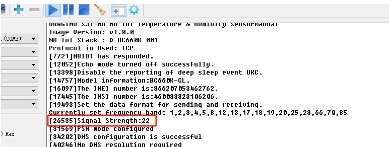
If end device successfully attached NB-IoT Network, User can normally see the signal strengh as below (between 0~31)
If fail to attach network, it will shows signal 99. as below:
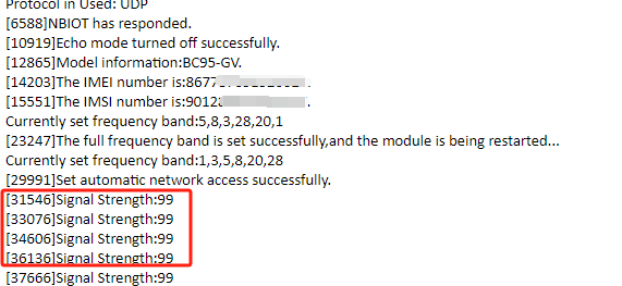
When see this issue, below are the checklist:
- Does your SIM card support NB-IoT network? If SIM card doesn't not specify support NB-IoT clearly, normally it doesn't support. You need to confirm with your operator.
- Do you configure the correct APN? Check here for APN settings.
- Do you lock the frequency band? This is the most case we see. Explain and Instruction: see section 1. Configure Frequency Band above.
- Check if the device is attached to Carrier network but reject. (need to check with operator).
- Check if the antenna is connected firmly.
If you have check all above and still fail. please send console log files (as many as possible) to support@dragino.com so we can check.
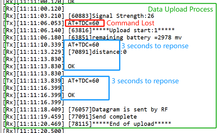
7.2 Why sometime the AT Command is slow in reponse?
When the MCU is communicating with the NB-IoT module, the MCU response of AT Command will become slower, it might takes several seconds to response.
7.3 GPS debugging
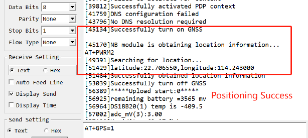
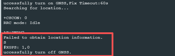
Indoor GPS signal is very weak, outdoor positioning is generally recommended.
7.3.1 GPS commands
The following are three related AT commands that introduce GPS functions.
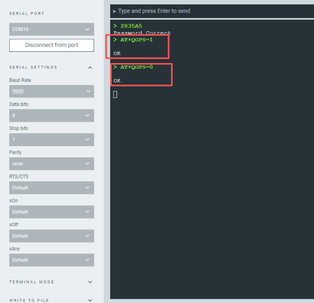
- **Turn on/off GPSAT Command: AT+QGPS Ex1: **AT+QGPS=0 // Turn off GPS
**Ex2: **AT+QGPS=1 // Turn on GPS
Downlink command: 0x11
Format: Command Code (0x11) followed by 1 byte.
Example: Downlink Payload: **11 01 **// AT+GPS=1
- Set GTIME open time
Extend the time to turn on GTIME. The automatic GPS location time is extended when the node is activated.
AT Command: AT+GTIME
Example: AT+GTIME=30 // Set the GPS positioning time to 30 seconds
Downlink command: 0x10
Format: Command Code (0x10) followed by 2 bytes.
Example: Downlink Payload: **10 00 1E **// AT+GTIME=30
- Set GPS positioning interval
Feature: Set GPS positioning interval (unit: hour).
When GPS is enabled, the node automatically locates and uplinks each time it passes GTDC time after activation.
AT Command: AT+QGTDC
Example: AT+QGTDC=24 // Set the GPS positioning interval to 24h.
Downlink command: 0x12
Format: Command Code (0x12) followed by 3 bytes.
Example: 24 hours: 24(D)=0x18(H)
Downlink Payload: **12 00 00 18 **// AT+QGTDC=24
7.3.2 GPS workflow
The whole working process after the GPS function is enabled(AT+QGPS=1) is as follows:
1. When activate the node, the node will turn on the GTIME, if the GPS signal is good, the node will print and upload the position information with the first data packet immediately.
If the signal is not good, it may take the whole **GTIME** time but still can not search the latitude and longitude information, at this time the node uploads the latitude and longitude all to 0.

So if there is a failure of positioning, the user can extend the **GTIME** time appropriately.
2. Each TDC time node is not repositioned and the positioning interval is determined by the AT+QGTDC time.
The latitude and longitude payload uplinked at each TDC time is the GPS positioning information from the previous QGTDC time.
Only when the node is activated or every QGTDC time is reached, the node turns on the GTIME and we can observe the GPS search information through the serial assistant or Bluetooth tool.
7.3.3 GPS debugging methods
In summary, we can deduce the methods of debugging GPS:
- Check whether the GPS function is enabled.
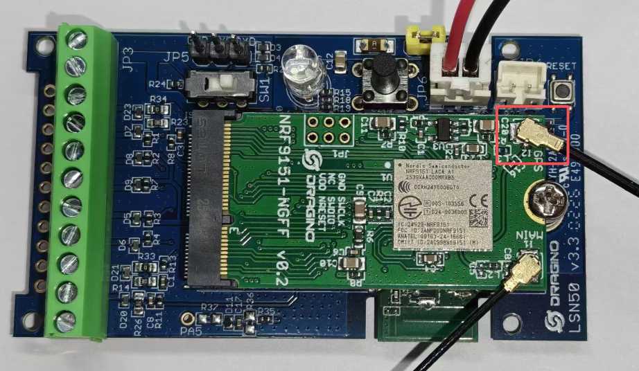
- Check whether the GPS antenna is loose.
If the GPS antenna is loose, the GPS signal is weak, and the positioning fails.
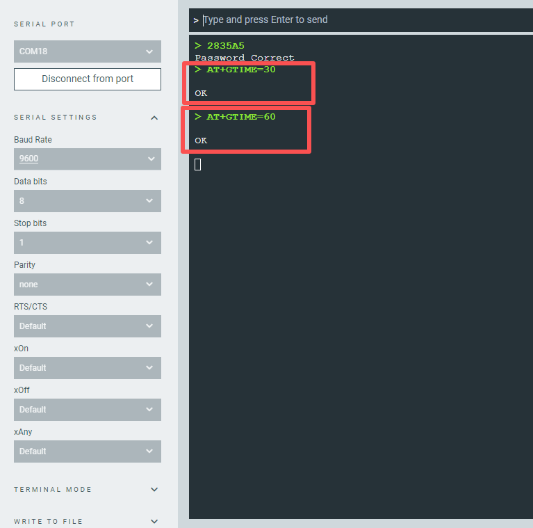
- Use the AT+GTIME command to extend the positioning time.
The default AT+GTIME=30, that is, the default positioning time is 30 seconds.
If the location fails, users can extend the location time.
7.4 How to get the debug log for further analyze?
FB model use the same debug instruction as NB model. Please check this link: