SE0X-MS Multi-Probe Soil Moisture and EC Mesh Node
1. Introduction
1.1 What is the Dragino Multi-Probe Mesh Soil Moisture and EC Sensor?
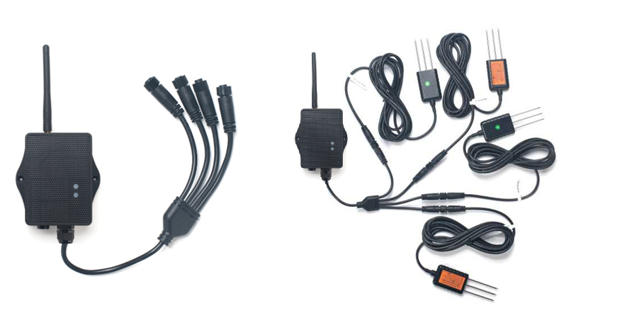
SE0X-MS is a Dragino Mesh Node for monitoring soil conditions at several depths or locations from one device. It supports up to four external probes, and each probe measures soil moisture, soil temperature, and soil electrical conductivity.
Every probe is identified by an address from 01 to 04. The node reads the connected probes and sends their measurements to a Dragino Mesh gateway, either directly or through other Mesh Nodes.
The soil probes use the FDR method for moisture measurement, with compensation from soil temperature and conductivity. They are factory calibrated for mineral soil and are intended especially for saline-alkali and loamy soil.
1.2 Features
- Up to four external soil probes.
- Soil moisture, temperature, and conductivity from each probe.
- Addresses
01to04to keep probe data separated. - Approximately
3.5 mcable length for each probe. - LoRa Mesh communication with multi-hop relaying.
- S-type outdoor enclosure, solar panel, and 3000 mAh rechargeable lithium battery.
- Automatic scheduled collection of connected-probe measurements.
- Probe data, battery information, and device status displayed on the Mesh gateway.
- Firmware upgrades through USB serial or PC BLE.
1.3 Specifications
Common DC characteristics
| Item | Specification |
|---|---|
| Main unit operating voltage | Approximately 2.5 V to 3.6 V |
| Main unit operating temperature | -40 °C to 85 °C; battery operating temperature is subject to the battery specification |
Soil moisture
| Item | Specification |
|---|---|
| Range | 0 to 100.00 % V/V |
| Resolution | 0.01 % V/V |
| Accuracy | ±3 % from 0 to 53 % V/V; ±5 % above 53 % V/V |
| Measurement method | FDR with temperature and conductivity compensation |
Soil temperature
| Item | Specification |
|---|---|
| Range | -40.00 °C to 85.00 °C |
| Resolution | 0.01 °C |
| Accuracy | Less than 0.3 °C from -10 °C to 50 °C; less than 0.6 °C outside this range |
| Measurement method | Calibrated RTD measurement |
Soil conductivity
| Item | Specification |
|---|---|
| Range | 0 to 20000 µS/cm at 25 °C |
| Resolution | 1 µS/cm |
| Accuracy | 2 % FS |
| Measurement method | Conductivity measurement with temperature compensation |
Multi-probe system
| Item | Specification |
|---|---|
| Maximum number of probes | 4 |
| Supported addresses | 01, 02, 03, and 04 |
| Factory-default probe address | 01 |
| Measurements per probe | Soil moisture, soil temperature, and soil conductivity |
| Probe operating voltage | 5 V to 24 V |
| Current per powered probe | Peak less than 30 mA; average less than 10 mA |
| Response time | Less than 1 second |
| Measurement stable time | Less than 2 seconds |
| Cable length | 3500 mm, deviation ±30 mm |
| Protection rating | IP68 |
| Approximate measurement volume | Cylinder 7 cm in diameter and 10 cm high, centered on each probe's central pin |
Mesh main unit
| Item | Specification |
|---|---|
| MCU | STM32WLE5, 48 MHz ARM Cortex-M4 |
| Flash | 256 KB |
| RAM | 64 KB |
| Radio | STM32WLE5 integrated sub-GHz LoRa radio |
| Power supply | Solar panel + 3000 mAh rechargeable lithium battery |
| Local interfaces | 3.3 V UART, BLE |
| Antenna | Sub-GHz LoRa antenna matching the shipping Region |
1.4 Applications
- Multi-depth monitoring through the crop root zone.
- Comparison of several field zones using one Mesh Node.
- Irrigation monitoring in greenhouses, orchards, nurseries, landscaping, and open fields.
- Distributed soil temperature and conductivity monitoring at remote sites.
1.5 Sleep Mode and Working Mode
In the sleep state, the node disables most functions and remains in low-power standby until its next scheduled wake-up or a user action wakes it.
After enrollment, the normal working cycle is:
Reach scheduled time -> Wake up -> Read connected probe addresses
                     -> Send grouped measurements to the Mesh gateway
                     -> Wait for a short communication window -> Sleep
Reading more connected probes extends the measurement activity performed during each cycle.
1.6 Button Operations and LED Status
Button operations and LED indications are common to Dragino Mesh Nodes. See 3.1 Button Operations and LED Status in the Mesh Quick Start for everyday operations. For factory reset, manual sleep, and Bootloader entry, see How to Use Advanced Button Operations.
1.7 BLE and Local Interfaces
SE0X-MS provides 3.3 V UART and BLE local interfaces. BLE can be used for normal APP firmware updates from a PC through PC BLE in FirmwareUpdateUtility.
The mobile upgrade workflow is still under development.
1.8 Enclosure and Mechanical Reference
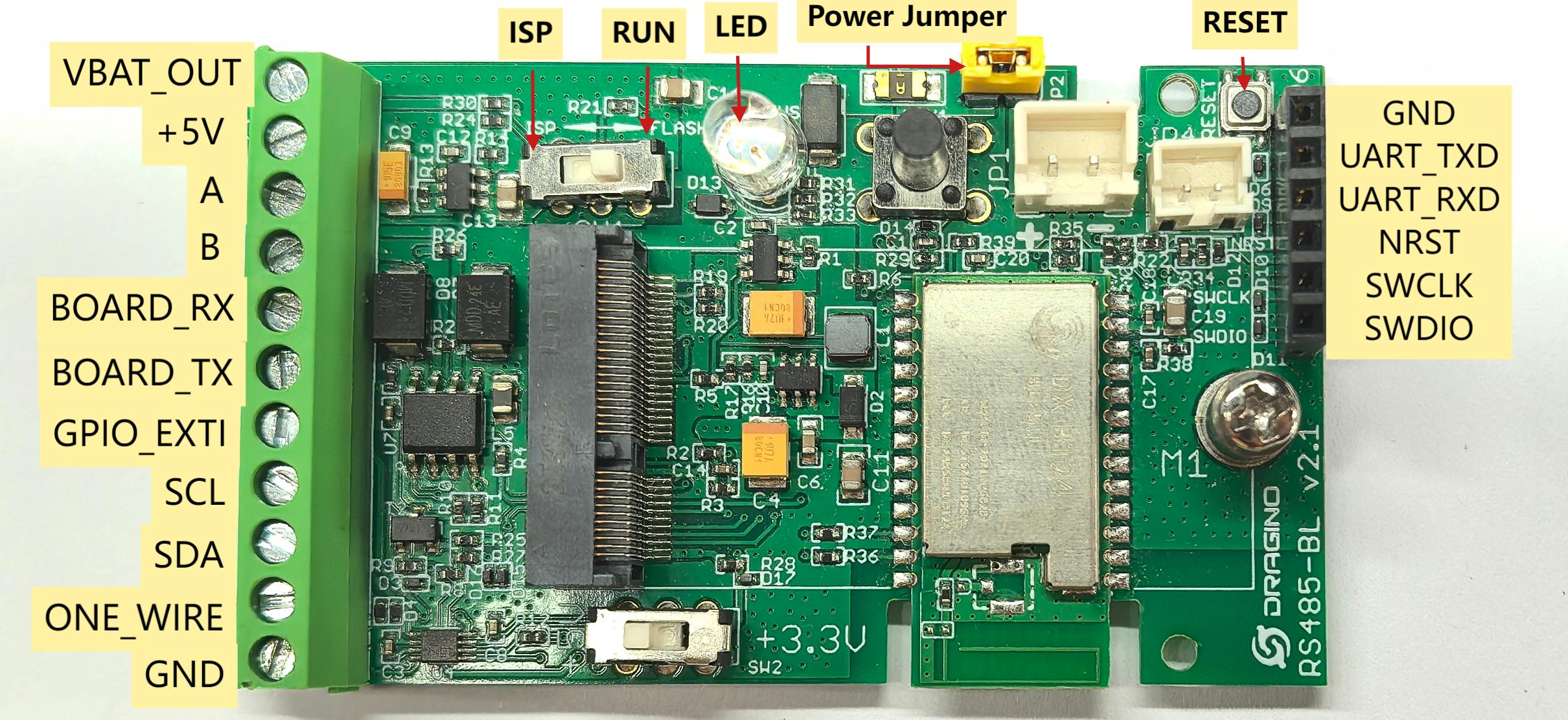
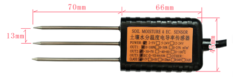
The following figures show the pin definitions, soil probe dimensions, and sensor cable dimensions used by SE0X-MS.
Pin definitions
Soil probe dimensions
Sensor cable dimensions

1.9 Multi-Probe Organization
The probe address associates each measurement with a physical location. Two probes connected to the same node must not share an address because their responses would conflict.
SE0X-MS
   ├── Probe 01 -> Moisture + Temperature + Conductivity
   ├── Probe 02 -> Moisture + Temperature + Conductivity
   ├── Probe 03 -> Moisture + Temperature + Conductivity
   └── Probe 04 -> Moisture + Temperature + Conductivity
1.9.1 Required Probe Addresses
New probes use address 01 by default. A multi-probe installation requires a unique address for each probe:
First probe  : keep address 01
Second probe : assign address 02
Third probe  : assign address 03
Fourth probe : assign address 04
Do not connect two probes with the same address to the node. Address changes must be performed with only one probe connected at a time. After every probe has a unique address, reconnect the required group and confirm that each address appears separately on the Mesh gateway before burial.
1.9.2 Recording the Installation Plan
Label every cable with its probe address and record what the address represents.
Example: one location, several depths
01 = Root zone, 20 cm
02 = Root zone, 40 cm
03 = Root zone, 60 cm
04 = Deep reference, 80 cm
Example: several locations at one depth
01 = Zone A, 30 cm
02 = Zone B, 30 cm
03 = Zone C, 30 cm
04 = Zone D, 30 cm
Keep the address-to-location record with the site documentation so gateway values can be matched to their buried positions.
1.10 Measurement Planning and Installation in Soil
Each probe measures the soil volume immediately surrounding its rods. For meaningful comparison, keep the installation method consistent and change only the variable the project intends to study, such as depth or field zone.
Moisture, temperature, and conductivity should be considered together. Conductivity can be influenced by salinity, fertilizer, moisture distribution, and soil composition; it does not identify individual nutrients.
1.10.1 Selecting Probe Positions
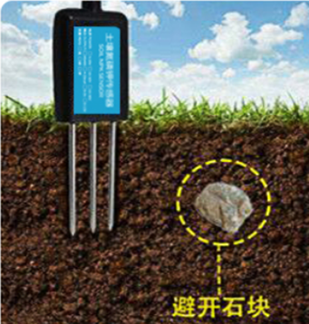
Avoid rocks, large roots, pipes, buried metal, and empty spaces within the sensing volume. Do not place a probe directly beside an irrigation outlet, drainage channel, or fertilizer deposit unless that local condition is intentionally being monitored.
Plan cable routing before burial and avoid tension, crushing, sharp bends, and areas where machinery can damage the cable.
1.10.2 Temporary Measurement
For spot checks, open the soil to the target depth and insert the probe vertically. Preserve the original soil density, insert the probe steadily without shaking, and restore firm contact around all rods before taking the reading.
1.10.3 Permanent Installation
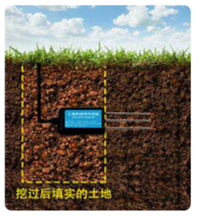
For long-term monitoring, dig an access hole larger than 20 cm and insert the probe horizontally into an undisturbed sidewall at the planned depth. Remove air gaps, backfill the hole, and restore the soil density as closely as possible.
Install the enclosure above ground with the cable outlet facing downward. Protect cable connections and provide a drip loop.
1.10.4 Installation Check
Trigger a report before burial and confirm that every expected address appears on the Mesh gateway. After installation, trigger another report and compare the gateway fields with the address-to-location record.
2. Mesh Operation
2.1 How It Works
The node can communicate directly with a Mesh gateway or relay its data through other awake Mesh Nodes.
The gateway groups measurements by probe address:
Probe 01 : Soil moisture | Soil temperature | Soil conductivity
Probe 02 : Soil moisture | Soil temperature | Soil conductivity
Probe 03 : Soil moisture | Soil temperature | Soil conductivity
Probe 04 : Soil moisture | Soil temperature | Soil conductivity
Node     : Battery status | Online status | Data update time
Only connected and successfully read probes produce measurement data. Display names, units, and page layout depend on the Mesh gateway version.
2.2 Product-Specific Verification
Complete the general enrollment and first-report procedure in the Mesh Quick Start before burying the probes. The verification must preserve the relationship between each probe address and its physical location.
| Stage | Verify | Expected result |
|---|---|---|
| Address plan | A unique address from 01 to 04 for every connected probe | No two probes share an address, and every cable is labeled with its location or depth |
| Before burial | A report with all probes connected and their address-to-location record available | Each expected address appears with one moisture, temperature, and conductivity group |
| Missing or unused slots | The detected_mask and the fixed slot layout | A clear mask identifies connected probes; an unused slot is not decoded as a measurement |
| Final installation | Probe depth, cable routing, enclosure position, and a second report | Every received address still matches the recorded physical location and the measurements are plausible |
2.3 Mesh Payload
SE0X-MS sends its business payload to the Mesh gateway on Mesh application port 290. Port 287 is used for configuration and administration messages and is not part of this sensor payload.
The common 14-byte header is documented in 2.4 Mesh Business Data. This section defines the DATA block for SE0X-MS.
SE0X-MS uses data_type = 0x03. The DATA block is 29 bytes, so the complete payload is always 43 bytes. Multi-byte values are little-endian.
The body has a 2-byte probe summary followed by four fixed 6-byte slots, one slot per Modbus address 1–4. A slot does not contain an address byte. Use detected_mask to decide which probes are present. Unused slots are zeros. valid_probe_count equals the number of bits set in detected_mask.
DATA Structure
DATA offset | Field | Format | Interpretation |
|---|---|---|---|
| 0–1 | battery_mv | uint16 LE | Battery voltage in mV; 0 = invalid |
| 2 | battery_percent | uint8 | Battery level 0–100; 0xFF = invalid |
| 3 | detected_mask | uint8 | Bit 0 = address 01, bit 1 = 02, bit 2 = 03, bit 3 = 04 |
| 4 | valid_probe_count | uint8 | Number of occupied slots; range 0–4 |
| 5–10 | Probe slot address 01 | 6 bytes | See probe slot format |
| 11–16 | Probe slot address 02 | 6 bytes | See probe slot format |
| 17–22 | Probe slot address 03 | 6 bytes | See probe slot format |
| 23–28 | Probe slot address 04 | 6 bytes | See probe slot format |
Probe Slot Format
| Slot offset | Field | Format | Interpretation |
|---|---|---|---|
| 0–1 | soil_moisture_x100 | uint16 LE | Raw value / 100 = % V/V; 65535 = invalid |
| 2–3 | soil_temperature_c_x100 | int16 LE | Raw value / 100 = °C; 32767 = invalid |
| 4–5 | soil_ec_us_cm | uint16 LE | Raw value = µS/cm; 65535 = invalid |
Do not decode a zeroed slot as a measurement when the corresponding detected_mask bit is clear. If no probe can be read, the node still sends the 43-byte payload with detected_mask = 0, valid_probe_count = 0, and all slots zero.
3. Configure SE0X-MS
3.1 Configuration Method
Common Mesh configuration is managed through the Mesh gateway. Use the Mesh Quick Start for the current configuration and enrollment workflow.
3.2 Region and Radio Parameters
Each unit ships with a fixed Region and LoRa parameters set during manufacturing. The Mesh gateway and node must use the same Region.
3.3 Scheduled and Manual Reporting
After enrollment, the node follows the wake-up and reporting schedule provided by the Mesh gateway.
To request an immediate update:
- Wake the node if it is sleeping.
- While it is active, hold the button and release it within 1 to 3 seconds.
- Allow the complete connected-probe measurement cycle to finish.
- Confirm that the new probe data and update time appear on the gateway.
3.4 Change a Probe Address
The user-facing procedure for changing an SE0X-MS probe address is currently under development. The required tool, connection, commands, and verification steps will be added in a future documentation update.
4. Battery & Power Consumption
Battery performance depends on the reporting interval, number of connected probes, Mesh coverage, relay conditions, sunlight, solar-panel orientation, ambient temperature, and battery condition.
Reading more probes extends each measurement cycle. SE0X-MS uses a solar panel and a 3000 mAh rechargeable lithium battery.
Battery Info & Power Consumption Analyze.
5. Firmware Update
Use only APP firmware built for SE0X-MS and the device's shipping Region.
For the firmware preparation and upload procedure, see 2. How to upload the firmware.
The mobile upgrade feature is still under development.
6. FAQ
6.1 Why must every probe have a unique address?
The address identifies the probe and associates its measurements with a physical location. Duplicate addresses cause response conflicts and prevent the gateway from separating the probes correctly.
6.2 Why are one or more probe addresses missing?
Check the missing probe's cable and connection. Confirm that its address is within 01 to 04, is unique, and was visible during the before-burial test.
6.3 How should abnormal measurements from one probe be checked?
Inspect the soil contact, air gaps, rocks, cable damage, depth, and installation position of that probe. Compare moisture, soil type, fertilizer history, and depth before treating a conductivity difference as a sensor fault.
6.4 How should a multi-probe installation be maintained?
- Keep cable labels readable and maintain the address-to-location record.
- Verify a replacement probe's address before reconnecting the complete group.
- After excavation or soil disturbance, restore firm soil contact and trigger a report.
- Inspect the solar panel, antenna, enclosure, connectors, and every probe cable.
- Clean heavy soil deposits with clean water and a soft cloth or brush.
For enrollment, Region, gateway connectivity, general power, or firmware-update questions, see the general Mesh FAQ.
7. Order Info
Ordering details, supported probe combinations, and Region-specific part numbers for SE0X-MS will be added when the product options are finalized.
8. Packing Info
Package contents, probe options, dimensions, and weights for SE0X-MS will be added in a future documentation update.
9. Support
Dragino support is available Monday to Friday from 09:00 to 18:00 GMT+8. When requesting assistance, provide the product model, firmware identification, Region, connected probe addresses, address-to-location record, and the steps required to reproduce the problem.
Contact: Support@dragino.cc