SDI-12-MS SDI-12 Sensor Interface Mesh Node
1. Introduction
1.1 What is the Dragino Mesh SDI-12 Sensor Interface?
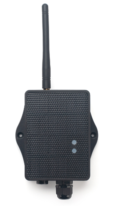
SDI-12-MS is a Dragino Mesh Node that connects SDI-12 sensors to a Dragino Mesh network. It acts as the SDI-12 master, powers the connected sensor, sends configured commands, processes the responses, and reports the selected data to a Mesh gateway.
The node does not assume a specific sensor model or measurement type. The commands and the way response data are published are defined in the product configuration, allowing the same node to work with different compatible environmental, agricultural, and weather sensors.
The node can communicate directly with a Dragino Mesh gateway or relay its data through other awake Mesh Nodes.
1.2 Features
- SDI-12 master interface for compatible external sensors.
- Standard SDI-12 communication at
1200 baud,7E1. - Configurable
3.3 V,5 V, and12 Vsensor power control. - Up to 15 command slots executed in order during each acquisition.
- Configurable command wait time and automatic
D0data request. - Required, optional, or no-response behavior for each slot.
- Normal, SDI-12 CRC, or non-standard response validation.
- Numeric and raw-byte output mapping.
- Automatic payload fragmentation when the configured record exceeds one Mesh packet.
- LoRa Mesh communication with multi-hop relaying.
- Solar panel and 3000 mAh rechargeable lithium battery.
- Scheduled acquisition followed by low-power sleep.
- Firmware upgrades through USB serial or PC BLE.
1.3 Specifications
Common DC characteristics
| Item | Specification |
|---|---|
| Main unit operating voltage | Approximately 2.5 V to 3.6 V |
| Main unit operating temperature | -40 °C to 85 °C; battery operating temperature is subject to the battery specification |
SDI-12 interface
| Item | Specification |
|---|---|
| Interface role | SDI-12 master |
| Communication | 1200 baud, 7 data bits, even parity, 1 stop bit |
| Command slots | Up to 15 |
| Maximum command length | 40 ASCII bytes |
| Maximum canonical response | 100 bytes, excluding the final CR/LF |
| Slot wait time | 0–255 seconds |
| Sensor power outputs | Controlled 3.3 V, 5 V, and 12 V |
| 5 V output capacity | Up to 300 mA |
| 12 V output capacity | Up to 100 mA |
Confirm that the connected sensor's supply voltage, startup current, steady-state current, and warm-up requirements are compatible with the selected output.
Mesh main unit
| Item | Specification |
|---|---|
| MCU | STM32WLE5, 48 MHz ARM Cortex-M4 |
| Flash | 256 KB |
| RAM | 64 KB |
| Radio | STM32WLE5 integrated sub-GHz LoRa radio |
| Power supply | Solar panel + 3000 mAh rechargeable lithium battery |
| Local interfaces | 3.3 V UART, BLE |
| Antenna | Sub-GHz LoRa antenna matching the shipping Region |
1.4 Applications
- Soil-moisture, temperature, conductivity, and salinity monitoring.
- Weather-station and environmental sensor integration.
- Water-level, precipitation, and hydrological monitoring.
- Agricultural sensors that provide an SDI-12 interface.
- Multi-sensor installations using unique SDI-12 addresses.
- Remote sites requiring solar power and multi-hop wireless coverage.
1.5 Sleep Mode and Working Mode
In the sleep state, the node disables most functions and remains in low-power standby until its next scheduled wake-up or a user action wakes it.
After enrollment, the normal working cycle is:
Reach scheduled time -> Wake up -> Power the SDI-12 interface and sensor
                     -> Execute enabled command slots in order
                     -> Build and send the configured data record
                     -> Turn off the configured sensor outputs
                     -> Wait for a short communication window -> Sleep
The node completes one SDI-12 acquisition during each wake-up cycle. It remains awake while the SDI-12 bus or a fragmented Mesh transmission is active.
1.6 Button Operations and LED Status
Button operations and LED indications are common to Dragino Mesh Nodes. See 3.1 Button Operations and LED Status in the Mesh Quick Start for everyday operations. For factory reset, manual sleep, and Bootloader entry, see How to Use Advanced Button Operations.
1.7 BLE and Local Interfaces
SDI-12-MS provides 3.3 V UART and BLE local interfaces. BLE can be used for normal APP firmware updates from a PC through PC BLE in FirmwareUpdateUtility.
The mobile upgrade workflow is still under development.
1.8 Enclosure and Mechanical Reference
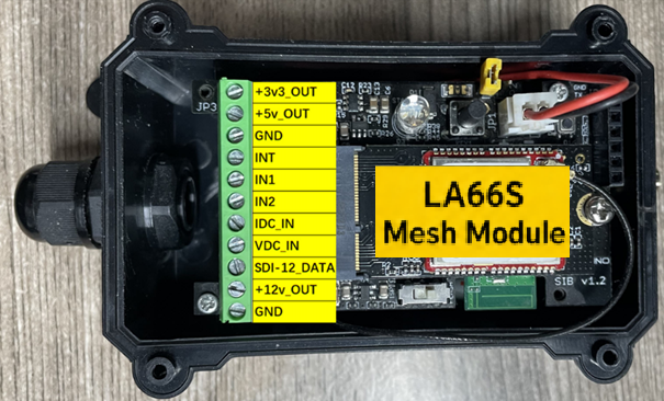
The following figures show the LA66S Mesh module pin definitions and the solar enclosure dimensions, mounting points, and cable outlet used by SDI-12-MS.
Pin definitions
Solar enclosure dimensions and mounting reference
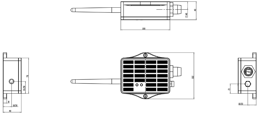
Install the enclosure above ground with the cable outlet facing downward. Select a cable gland suitable for the sensor cable, seal unused openings, and provide a drip loop so water does not run along the cable toward the enclosure.
1.9 SDI-12 Commands and Published Data
1.9.1 Command Slots
SDI-12-MS supports up to 15 command slots. Enabled slots run in order from Slot 1 to Slot 15. A disabled slot is skipped.
Each enabled slot defines:
- A complete SDI-12 command.
- The fixed wait time after that command.
- Whether an automatic
D0request is required. - How the response is validated.
- Whether the response is required, optional, or not expected.
- Which numeric values or raw bytes are added to the published record.
A command can contain up to 40 ASCII bytes. It normally starts with the sensor address and ends with !; ?! is supported when querying a sensor address.
1.9.2 Wait Time and Automatic D0
The configured wait time is used after the first command, whether that command succeeds or fails. The node does not calculate this delay from the time reported by a measurement acknowledgement.
When automatic D0 is enabled for a successful standard measurement command, the node waits for the configured time and then requests the measured data using the same sensor address. The slot publishes the D0 response rather than the measurement acknowledgement.
1.9.3 Response Behavior and Validation
| Setting | Options | Purpose |
|---|---|---|
| Response behavior | Required, Optional, None | Defines whether a valid response must be received |
| Validation | Normal, SDI CRC, None | Selects standard address/format checking, SDI-12 CRC checking, or support for a non-standard response |
Required is the default response behavior. Normal validation checks a standard printable SDI-12 response and its address. SDI CRC validation additionally verifies the SDI-12 CRC when the data command requires it. None is intended only for a compatible sensor that returns a documented non-standard response.
1.9.4 Output Mapping
| Output mode | Published data |
|---|---|
| None | The command runs but contributes no bytes to the record |
| Numeric | Selected signed values are scaled and stored as 1-, 2-, 3-, or 4-byte little-endian integers |
| Raw | The complete canonical response or up to three configured byte ranges is published with a length prefix |
Numeric mode can select up to 20 signed values from one response. The configured precision must represent the source value exactly; otherwise that slot is omitted from the record.
Raw mode supports up to 100 response bytes per slot. If a configured range extends beyond the received response, that slot is omitted.
If any required extraction or conversion fails, the complete output of that slot is omitted. Other successful slots can still contribute data.
1.10 Installation
- Confirm that every connected device supports SDI-12 communication.
- Check the sensor supply voltage, peak current, steady-state current, startup delay, and wiring.
- Assign a unique SDI-12 address to each sensor that shares the bus.
- Connect the SDI-12 data, power, and ground conductors according to the sensor documentation.
- Configure the sensor power policy and warm-up time before testing commands.
- Test each sensor and command slot individually before enabling the complete sequence.
- Confirm the expected numeric values or raw data on the Mesh gateway.
- Install the enclosure above ground, keep the cable outlet facing downward, and provide a drip loop.
- Place the solar panel where it receives stable, unobstructed sunlight.
- Trigger another report after final installation and verify the complete acquisition.
Do not connect a sensor until its supply voltage, current, polarity, and SDI-12 wiring have been confirmed. Exceeding an output rating or connecting a signal to the wrong terminal can damage the node or sensor.
2. Mesh Operation
2.1 How It Works
The node can communicate directly with a Mesh gateway or relay its data through other awake Mesh Nodes.
During each scheduled acquisition, the node powers the SDI-12 interface, executes the enabled slots, and combines the successful slot outputs into one record. The Mesh gateway receives:
- Data selected by the configured Numeric or Raw mappings.
- A status mask identifying the successful slots.
- Battery voltage and battery level.
- Device online status and data update time.
Because SDI-12-MS does not assign measurement meanings or units, the gateway or application decoder must use the same slot configuration that was used to build the record.
2.2 Product-Specific Verification
Complete the general enrollment and first-report procedure in the Mesh Quick
Start before final installation.
For SDI-12-MS, validate the sensor bus and the configured record before the
complete command sequence is placed in service.
| Stage | Verify | Expected result |
|---|---|---|
| Bus and power | Sensor address, supply voltage, polarity, current, warm-up, and SDI-12 wiring | The sensor powers correctly and communicates without exceeding the node's output limits |
| Command slots | Each enabled command and its configured wait time, validation, response behavior, and output mapping | Every required slot returns the expected Numeric or Raw output; optional or empty slots behave as configured |
| Acquisition record | A complete scheduled or manual acquisition | The status mask identifies successful slots and the record contains only the outputs from those slots |
| Fragmented record | Any acquisition longer than one packet | All fragments are received and reassembled in order using their acquisition identifier and descriptor |
| Final installation | Cable protection, enclosure position, and one complete acquisition after mounting | The expected slots remain valid and the sensor installation is mechanically and electrically secure |
2.3 Mesh Payload
SDI-12-MS sends its business payload to the Mesh gateway on Mesh application port 290.
The common 14-byte header is documented in 2.4 Mesh Business Data. This section defines the DATA layouts for SDI-12-MS.
SDI-12-MS uses data_type = 0x06. Battery information is followed by a 16-bit slot-status mask and the configured data record. Multi-byte values are little-endian.
The status mask uses bits 0–14 for Slots 1–15. A set bit means that the corresponding slot completed successfully and contributed its configured output. A failed or skipped slot contributes no bytes; there is no padding. Bit 15 indicates a fragmented payload.
Single-Packet DATA Structure
When the combined record is 214 bytes or less, it is sent in one payload.
DATA offset | Field | Format | Interpretation |
|---|---|---|---|
| 0–1 | battery_mv | uint16 LE | Battery voltage in mV; 0 = invalid |
| 2 | battery_percent | uint8 | Battery level 0–100; 0xFF = invalid |
| 3–4 | slot_status_mask | uint16 LE | Bits 0–14 identify successful slots; bit 15 = 0 |
| 5… | record | Variable | Concatenated output from successful slots |
The complete payload length is 19 + record length, up to 233 bytes.
Fragmented DATA Structure
When the combined record exceeds 214 bytes, the node divides it into two to four fragments. Each fragment carries up to 211 bytes of record data.
DATA offset | Field | Format | Interpretation |
|---|---|---|---|
| 0–1 | battery_mv | uint16 LE | Battery voltage in mV; 0 = invalid |
| 2 | battery_percent | uint8 | Battery level 0–100; 0xFF = invalid |
| 3–4 | slot_status_mask | uint16 LE | Bits 0–14 identify successful slots; bit 15 = 1 |
| 5–6 | cycle_id | uint16 LE | Identifies fragments from the same acquisition |
| 7 | fragment_descriptor | uint8 | High nibble = fragment count minus 1; low nibble = zero-based fragment index |
| 8… | record_fragment | Up to 211 bytes | Part of the combined record |
The combined record is limited to 844 bytes. The receiver must collect every fragment with the same cycle_id and place them in descriptor order. If a fragment is missing, that acquisition record is incomplete.
To decode the record, use the saved slot configuration together with slot_status_mask. The record contains only successful slot outputs in slot order.
3. Configure SDI-12-MS
3.1 Configuration Method
Common Mesh configuration is managed through the Mesh gateway. Use the Mesh Quick Start for the current enrollment and network workflow.
SDI-12 product configuration is available through the Mesh gateway or a supported configuration tool such as the SDI-12 page in MeshDebug. Product configuration uses Mesh port 294.
3.2 Region and Radio Parameters
Each unit ships with a fixed Region and LoRa parameters set during manufacturing. The Mesh gateway and node must use the same Region.
3.3 Scheduled and Manual Reporting
After enrollment, the node performs one acquisition during each scheduled wake-up cycle.
To request an immediate update:
- Wake the node if it is sleeping.
- While it is active, hold the button and release it within 1 to 3 seconds.
- Allow the configured command sequence and any fragmented transmission to finish.
- Confirm that the new slot status and data appear on the Mesh gateway.
Configuration saved after an acquisition has been completed applies to the next acquisition. It does not reinterpret a record that has already been created.
3.4 Configure Sensor Power
Configure the sensor power policy before testing the command slots:
- Sensor warm-up: additional startup delay before the first command; default
1000 ms. - 3.3 V: always on, acquisition only, or always off.
- 5 V: enabled during acquisition, with an option to keep it on while the node sleeps.
- 12 V: enabled only during acquisition.
The default configuration keeps 3.3 V on, turns 5 V off while sleeping, and uses a 1000 ms sensor warm-up delay.
Use the shortest warm-up time that still allows the connected sensor to respond reliably. Keeping an output enabled during sleep increases power consumption.
3.5 Configure and Test Command Slots
For each required slot:
- Enable the slot and enter the complete SDI-12 command.
- Set the required wait time.
- Enable automatic
D0when the measurement workflow requires it. - Select the response behavior and validation method.
- Configure Numeric, Raw, or None output.
- Test the draft slot before saving it.
- Verify the response and mapped output.
After all slots pass, save the complete configuration and review the payload forecast. The forecast indicates whether the maximum configured record fits in one Mesh payload or requires fragmentation.
If no slots are enabled, the node still publishes battery information and a zero slot-status mask.
3.6 Query or Change a Sensor Address
The supported SDI-12 configuration interface can query a sensor address and change an address when required through Meshdebug.
Connect only the intended sensor while changing an address. The query-address command can produce overlapping responses when several sensors share the bus, especially when they still use the same default address.
After changing an address, verify the sensor with its new address before reconnecting the complete group and saving the final command slots.
4. Battery & Power Consumption
Battery performance depends on the reporting interval, number of enabled slots, configured wait times, sensor warm-up time, sensor current, retained power outputs, Mesh coverage, relay conditions, sunlight, solar-panel orientation, ambient temperature, and battery condition.
Long command sequences, long waits, high-current sensors, fragmented transmissions, and keeping 5 V enabled during sleep increase power consumption.
SDI-12-MS uses a solar panel and a 3000 mAh rechargeable lithium battery.
Battery Info & Power Consumption Analyze.
5. Firmware Update
Use only APP firmware built for SDI-12-MS and the device's shipping Region.
For the firmware preparation and upload procedure, see 2. How to upload the firmware.
The mobile upgrade feature is still under development.
6. FAQ
6.1 Why is the node enrolled but no sensor values appear?
Confirm the sensor wiring, address, supply voltage, warm-up time, command, wait time, response behavior, and validation mode. Test the slot directly and check whether its bit is set in slot_status_mask.
6.2 Why is a complete slot missing from the payload?
The node omits the entire slot output if the command, response validation, numeric conversion, or raw-range extraction fails. There is no padding for failed slots. Use the status mask to identify which slots contributed data.
6.3 Why does automatic D0 return no data?
Automatic D0 runs only after a successful recognized measurement command. Confirm that the first command is a supported SDI-12 measurement command and that the configured wait time is long enough for the sensor.
6.4 Why does a sensor-address query fail with several sensors connected?
The query-address command asks all connected sensors to respond. Their replies can overlap. Connect one sensor at a time when identifying or changing addresses.
6.5 Why does the gateway receive several payloads for one acquisition?
The configured record is larger than the single-packet limit. SDI-12-MS divides it into fragments that share one cycle_id. The receiver must collect and reassemble every fragment.
6.6 How should SDI-12-MS be maintained?
- Keep the solar panel clean and unobstructed.
- Inspect the antenna, enclosure, cable gland, sensor cable, connections, and drip loop.
- Confirm that the sensor remains securely installed and properly powered.
- Retest the sensor address and commands after replacing or reconfiguring a sensor.
- Review the payload forecast after changing slot outputs.
- Trigger a manual acquisition after wiring, configuration, or firmware changes.
For enrollment, Region, gateway connectivity, general power, or firmware-update questions, see the general Mesh FAQ.
7. Order Info
Ordering details, cable-gland options, and Region-specific part numbers for SDI-12-MS will be added when the product options are finalized.
8. Packing Info
Package contents, dimensions, and weights for SDI-12-MS will be added in a future documentation update.
9. Support
Dragino support is available Monday to Friday from 09:00 to 18:00 GMT+8. When requesting assistance, provide the product model, firmware identification, Region, connected sensor model, sensor address, power settings, slot configuration, and the steps required to reproduce the problem.
Contact: Support@dragino.cc