CPL03-MS Three-Input Pulse and Contact Mesh Node

1. Introduction
1.1 What is the CPL03-MS Three-Input Pulse and Contact Mesh Node?
CPL03-MS is a Dragino Mesh Node with three digital inputs for monitoring dry contacts, pulse-output devices, and digital alarm states.
The node supports three Mesh work modes. Depending on the selected mode, it can monitor one door or contact with open statistics, accumulate pulses from three inputs, or report the current state and trigger source of three digital inputs.
CPL03-MS sends data directly to a Dragino Mesh gateway or through other awake Mesh Nodes.
1.2 Features
- Three digital inputs: Input 1, Input 2, and Input 3.
LOW = OPENandHIGH = CLOSEinput-state convention.- MOD1 for single-contact open/close monitoring.
- MOD2 for three-channel pulse counting.
- MOD3 for three-channel digital-state and alarm monitoring.
- Immediate event reporting in MOD1 and MOD3.
- Pulse accumulation during sleep in MOD2 without waking the radio for every pulse.
- LoRa Mesh communication with multi-hop relaying.
- Solar panel and 3000 mAh rechargeable lithium battery.
- Scheduled reporting and low-power sleep operation.
- Firmware upgrades through USB serial or PC BLE.
1.3 Specifications
Common DC characteristics
| Item | Specification |
|---|---|
| Main unit operating voltage | Approximately 2.5 V to 3.6 V |
| Main unit operating temperature | -40 °C to 85 °C; battery operating temperature is subject to the battery specification |
Digital inputs
| Item | Specification |
|---|---|
| Number of inputs | 3 |
| Input names | Input 1, Input 2, and Input 3 |
| LOW level | OPEN |
| HIGH level | CLOSE |
| Pulse-counting edge in MOD2 | Falling edge |
| Counter width | 24-bit unsigned counter per input |
| Maximum counter value | 16,777,215 |
The external circuit provides the input bias. CPL03-MS reads the resulting electrical level and interprets it using the OPEN/CLOSE convention above.
Mesh main unit
| Item | Specification |
|---|---|
| MCU | STM32WLE5, 48 MHz ARM Cortex-M4 |
| Flash | 256 KB |
| RAM | 64 KB |
| Radio | STM32WLE5 integrated sub-GHz LoRa radio |
| Power supply | Solar panel + 3000 mAh rechargeable lithium battery |
| Local interfaces | 3.3 V UART, BLE |
| Antenna | Sub-GHz LoRa antenna matching the shipping Region |
| Enclosure protection | IP67 |
1.4 Applications
- Door, window, and access-point monitoring.
- Dry-contact state monitoring.
- Water meters, flow meters, and other pulse-output devices.
- Three-channel alarm and equipment-state monitoring.
- Remote installations requiring solar power and multi-hop wireless coverage.
- Applications where frequent pulses must be accumulated without transmitting on every pulse.
1.5 Sleep Mode and Working Mode
In the sleep state, the node disables most functions and remains in low-power standby until its next scheduled wake-up, a user action, or a supported input event wakes it.
The normal scheduled cycle is:
Reach scheduled time -> Wake up -> Read the active mode and input data
                     -> Send data to the Mesh gateway
                     -> Wait for a short communication window -> Sleep
MOD1 and MOD3 can also wake and send after a supported input event. MOD2 continues counting pulses while the node sleeps and reports the accumulated totals during the next periodic or manual transmission.
1.6 Button Operations and LED Status
Button operations and LED indications are common to Dragino Mesh Nodes. See 3.1 Button Operations and LED Status in the Mesh Quick Start for everyday operations. For factory reset, manual sleep, and Bootloader entry, see How to Use Advanced Button Operations.
1.7 BLE and Local Interfaces
CPL03-MS provides 3.3 V UART and BLE local interfaces. BLE can be used for normal APP firmware updates from a PC through PC BLE in FirmwareUpdateUtility.
The mobile upgrade workflow is still under development.
1.8 Enclosure and Mechanical Reference
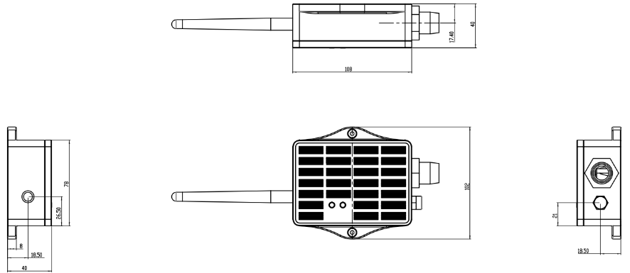
The following figures show the LA66S Mesh module pin definitions and the solar enclosure dimensions, mounting points, and cable outlets used by CPL03-MS.
Pin definitions
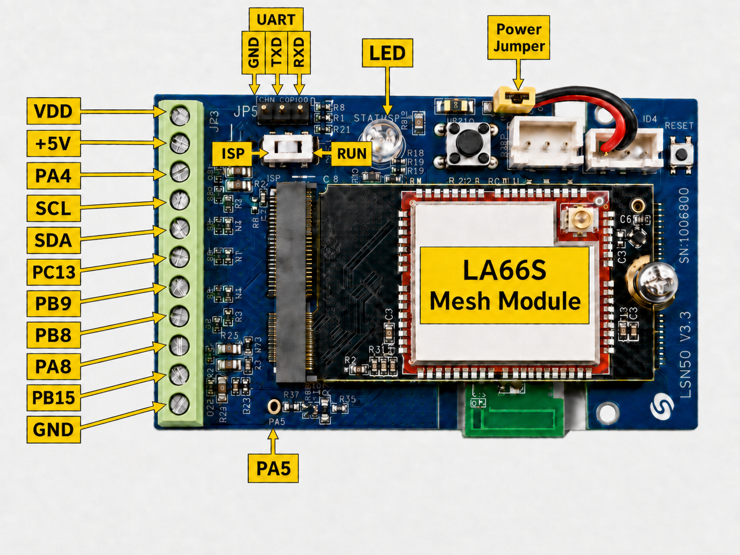
CPL03-MS uses the LSN50V3 base board. Some board silkscreen pin names differ from the STM32 pin names used in firmware. See How Board Pins Map to STM32 Pins Used in Firmware.
Solar enclosure dimensions and mounting reference
1.9 Input Connections and Work Modes
1.9.1 Input Connections
CPL03-MS provides three input pairs for field connections:
| Input | Signal wire | Board terminal | Companion wire |
|---|---|---|---|
| Input 1 | White | PA8 | Black, VDD |
| Input 2 | Red | PA4 | Yellow, internally connected to VDD |
| Input 3 | Green | PB15 | Orange, internally connected to VDD |
For a dry contact, connect the contact between the corresponding signal wire and its VDD companion wire. The yellow and orange wires share the VDD connection with the black wire at the device end, simplifying the internal terminal connection while keeping three separate contact pairs available at the field end.
For an externally powered digital output, connect the external circuit ground to the node ground and the signal output to the required input. The input voltage must remain within the supported level of the node and must not exceed 3.6 V.
Confirm the output voltage, polarity, common ground, and idle level of an externally powered device before connecting it. The external circuit is responsible for biasing the input; CPL03-MS reads the level as provided.
CPL03-MS supports only MOD1, MOD2, and MOD3. MOD1 is the default. If no valid product configuration is available, the node returns to MOD1.
The mode can be changed through Mesh configuration without reflashing the firmware. A mode change is applied immediately, clears the counters and tracked input state, and starts the new mode from the current input levels. A factory reset also restores MOD1.
1.9.2 MOD1 — Open/Close Monitoring
MOD1 uses only Input 1. It is intended for a door, window, or another single dry contact.
The node reports:
- Current state: OPEN or CLOSE.
- Accumulated number of openings.
- Duration of the last opening, in seconds.
The node sends during the scheduled reporting cycle and when the monitored contact opens or closes.
1.9.3 MOD2 — Three-Channel Pulse Counting
MOD2 uses all three inputs. Each falling edge increases the accumulated counter of the corresponding input by one.
The node counts pulses while sleeping and does not wake the radio for every pulse. The Mesh gateway receives the accumulated totals in the next scheduled report or after a manual transmission.
This mode is intended for pulse meters and frequent events where sending one wireless message for every pulse would increase airtime and power consumption.
1.9.4 MOD3 — Three-Channel Digital Status and Alarm
MOD3 uses all three inputs. It reports the current OPEN/CLOSE state of every input and identifies which input or inputs triggered an event report.
A falling-edge event on an input wakes the node and triggers a transmission. This mode is intended for three independent alarm or equipment-state contacts when immediate event notification is required.
1.10 Installation
- Select the work mode before final installation.
- Confirm the output type, voltage, polarity, idle level, and expected transition of every connected device.
- Disconnect power while completing field wiring.
- Keep unused conductors insulated and protected from moisture.
- Install the enclosure above ground with cable outlets facing downward.
- Provide a drip loop and protect the cable from pulling, crushing, and sharp bends.
- Install the LoRa antenna vertically and place the solar panel where it receives stable, unobstructed sunlight.
- Test every connected input and confirm the expected gateway values before completing the installation.
2. Mesh Operation
2.1 How It Works
The node can communicate directly with a Mesh gateway or relay its data through other awake Mesh Nodes.
The gateway data depend on the selected work mode:
MOD1 -> Input 1 state | Accumulated openings | Last-open duration
MOD2 -> Input 1 count | Input 2 count | Input 3 count
MOD3 -> Three input states | Input-event trigger source
Node -> Battery status | Online status | Data update time
Periodic reports are generated by the scheduled Mesh cycle. A manual report uses the same periodic reason. In MOD1 and MOD3, an input event can generate an additional event report. MOD2 accumulates pulses and normally reports them only periodically or manually.
2.2 Product-Specific Verification
Complete the general enrollment and first-report procedure in the Mesh Quick
Start before final installation.
Use the checks below to verify the selected CPL03-MS mode and field wiring.
| Stage | Verify | Expected result |
|---|---|---|
| Mode and wiring | The selected mode, input type, voltage, polarity, and idle level | The connected equipment matches the requirements in Input Connections and Work Modes |
| MOD1 | Open and close Input 1 | The state changes correctly, and an opening updates the count and last-open duration |
| MOD2 | Generate known pulses on Inputs 1–3 | Each falling edge increases the corresponding accumulated counter; no radio transmission is expected for every pulse |
| MOD3 | Trigger each configured input | The current states and the input-event trigger source are reported correctly |
| Final installation | Repeat the applicable test after mounting and cable routing | The mode-specific values remain consistent with the installed contacts or pulse sources |
2.3 Mesh Payload
CPL03-MS sends its business payload to the Mesh gateway on Mesh application port 290.
The common 14-byte header is documented in 2.4 Mesh Business Data. This section defines the mode-specific DATA blocks for CPL03-MS.
The data_type identifies the active work mode. Each mode has a fixed payload length and begins its DATA block with battery voltage and battery percentage. Multi-byte values are little-endian.
| Mode | data_type | DATA size | Complete payload |
|---|---|---|---|
| MOD1 | 0x14 | 12 bytes | 26 bytes |
| MOD2 | 0x15 | 13 bytes | 27 bytes |
| MOD3 | 0x16 | 6 bytes | 20 bytes |
reason = 1 identifies a periodic or manual report. reason = 2 identifies a report caused by an input event. In practice, MOD2 normally uses only the periodic reason because pulses are accumulated without waking the radio.
Battery voltage 0 and battery percentage 0xFF indicate unavailable battery data. The 24-bit counters contain accumulated counts and do not use sensor sentinel values.
MOD1 DATA Structure
DATA offset | Field | Format | Interpretation |
|---|---|---|---|
| 0–1 | battery_mv | uint16 LE | Battery voltage in mV; 0 = invalid |
| 2 | battery_percent | uint8 | Battery level 0–100; 0xFF = invalid |
| 3 | reason | uint8 | 1 = periodic or manual; 2 = input event |
| 4 | state | uint8 | 0 = OPEN; 1 = CLOSE |
| 5–7 | open_count | uint24 LE | Accumulated number of openings |
| 8–11 | last_open_duration_s | uint32 LE | Duration of the last opening in seconds |
MOD2 DATA Structure
DATA offset | Field | Format | Interpretation |
|---|---|---|---|
| 0–1 | battery_mv | uint16 LE | Battery voltage in mV; 0 = invalid |
| 2 | battery_percent | uint8 | Battery level 0–100; 0xFF = invalid |
| 3 | reason | uint8 | Normally 1 = periodic or manual |
| 4–6 | counter_1 | uint24 LE | Accumulated pulses on Input 1 |
| 7–9 | counter_2 | uint24 LE | Accumulated pulses on Input 2 |
| 10–12 | counter_3 | uint24 LE | Accumulated pulses on Input 3 |
MOD2 does not include an OPEN/CLOSE state byte.
MOD3 DATA Structure
DATA offset | Field | Format | Interpretation |
|---|---|---|---|
| 0–1 | battery_mv | uint16 LE | Battery voltage in mV; 0 = invalid |
| 2 | battery_percent | uint8 | Battery level 0–100; 0xFF = invalid |
| 3 | reason | uint8 | 1 = periodic or manual; 2 = input event |
| 4 | state_mask | uint8 | Bits 0–2 map Inputs 1–3; 1 = CLOSE |
| 5 | trigger_mask | uint8 | Bits 0–2 map Inputs 1–3; 1 = input triggered the event |
For periodic reports, trigger_mask is normally 0.
If the node cannot create a consistent mode snapshot, such as while a mode change is in progress, it does not send that frame.
3. Configure CPL03-MS
3.1 Configuration Method
Common Mesh configuration is managed through the Mesh gateway. Use the Mesh Quick Start for the current configuration and enrollment workflow.
The product-specific setting is the work mode. It is configured through the Mesh gateway or a supported configuration tool.
3.2 Region and Radio Parameters
Each unit ships with a fixed Region and LoRa parameters set during manufacturing. The Mesh gateway and node must use the same Region.
3.3 Scheduled, Manual, and Event Reporting
After enrollment, the node follows the wake-up and reporting schedule provided by the Mesh gateway.
To request an immediate periodic-type update:
- Wake the node if it is sleeping.
- While it is active, hold the button and release it within 1 to 3 seconds.
- Confirm that the new mode-specific data and update time appear on the Mesh gateway.
MOD1 and MOD3 can also transmit after a supported input event. MOD2 counts pulses without transmitting for each pulse.
3.4 Change the Work Mode
The user-facing procedure for changing the CPL03-MS work mode is currently under development. The required Mesh gateway or configuration-tool steps and verification procedure will be added in a future documentation update.
Changing the mode does not require reflashing the firmware. The new mode takes effect immediately, clears the counters and tracked state, and starts from the current input levels. Factory reset restores MOD1.
4. Battery & Power Consumption
Battery performance depends on the reporting interval, number and frequency of input events, Mesh coverage, relay conditions, sunlight, solar-panel orientation, ambient temperature, and battery condition.
MOD1 and MOD3 can consume additional power when input events cause extra transmissions. MOD2 avoids transmitting on every pulse and is better suited to frequent pulse sources.
CPL03-MS uses a solar panel and a 3000 mAh rechargeable lithium battery.
Battery Info & Power Consumption Analyze.
5. Firmware Update
Use only APP firmware built for CPL03-MS and the device's shipping Region.
For the firmware preparation and upload procedure, see 2. How to upload the firmware.
The mobile upgrade feature is still under development.
6. FAQ
6.1 Why does the gateway show OPEN when the input is LOW?
This is the electrical convention used by CPL03-MS: LOW means OPEN and HIGH means CLOSE. Confirm that the external circuit provides the intended bias and idle level.
6.2 Why does MOD2 not report every pulse immediately?
MOD2 is designed for frequent pulse sources. It counts falling edges while sleeping without waking the radio for every pulse. The gateway receives the accumulated totals during the next scheduled report or after a manual transmission.
6.3 What happens when the work mode is changed?
The new mode is applied immediately. Counters and tracked input state are cleared, and the node starts the new mode from the current input levels.
6.4 What happens when a pulse counter reaches its maximum?
Each pulse counter uses 24 bits. After reaching 16,777,215, the next counted pulse starts the counter again at 1.
6.5 Why are there six field wires but fewer internal terminal connections?
Each of the three inputs has a signal wire and a VDD companion wire at the field end. The VDD companion wires are joined internally, so only one VDD connection is required at the device terminal.
6.6 How should CPL03-MS be maintained?
- Keep the solar panel clean and unobstructed.
- Inspect the antenna, enclosure, cable entry, wiring, insulation, and drip loop.
- Keep unused conductors individually insulated and protected from moisture.
- Verify the external signal voltage and idle level after replacing a connected device.
- Trigger a manual report and repeat the input test after wiring or mode changes.
For enrollment, Region, gateway connectivity, general power, or firmware-update questions, see the general Mesh FAQ.
7. Order Info
Ordering details and Region-specific part numbers for CPL03-MS will be added when the product options are finalized.
8. Packing Info
Package contents, dimensions, and weights for CPL03-MS will be added in a future documentation update.
9. Support
Dragino support is available Monday to Friday from 09:00 to 18:00 GMT+8. When requesting assistance, provide the product model, firmware identification, Region, selected work mode, input wiring, external signal levels, and the steps required to reproduce the problem.
Contact: Support@dragino.cc