IM01v2
IM01v2 – Mesh Indoor Gateway User Manual
1. Introduction
1.1 What is IM01v2
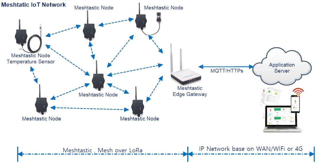
The IM01v2 Mesh Gateway is a LoRa-based Mesh edge gateway. It connects Meshtastic-compatible nodes, receives business data through the LoRa Mesh network, and can connect to MQTT/HTTPS application services through Ethernet, Wi-Fi or optional Cellular networking.
Mesh nodes can relay packets over multiple hops. Nodes can therefore communicate inside the Mesh network without Wi-Fi or cellular coverage. When the gateway has an IP uplink, it can send data to remote Web or mobile monitoring applications.
1.2 Specifications
Hardware System:
- CPU: Quad-core Cortex-A7 1.2Ghz
- RAM: 512MB
- eMMC: 4GB
Interface:
- 10M/100M RJ45 Ports x 1
- Multi-Channel LoRaWAN Wireless
- WiFi 802.11 b/g/n
- Sensitivity: -140dBm
- Max Output Power: 27dBm
Operating Condition:
- Work Temperature: -20 ~ 70°C
- Storage Temperature: -20 ~ 70°C
- Power Input: 5V, 2A, DC
1.3 Features
- Open Source Debian system
- Managed by Web GUI, SSH via WAN or WiFi
- Remote Management
- Auto-provisioning for batch deployment and management
- LoRaWAN Gateway
- 10 programmable parallel demodulation paths
- Pre-configured to support different LoRaWAN regional settings.
- Allow customizing LoRaWAN regional parameters.
- Different kinds of LoRaWAN Connections such as
- Semtech UDP Packet Forwarder
- LoRaWAN Basic Station
- ChirpStack-Gateway-Bridge (MQTT)
- Built-in ChirpStack local LoRaWAN server
- Built-in Node-Red local Application server
1.4 LED Indicators
IM01-V2 has totally four LEDs, They are:
➢ Power LED: This RED LED will be solid if the device is properly powered
➢ ETH LED: This RGB LED will blink GREEN when the ETH port is connecting
➢ SYS LED: This RGB LED will show different colors in different states:
✓ SOLID GREEN: The device is alive with a LoRaWAN server connection.
✓ BLINKING GREEN: a) Device has internet connection but no LoRaWAN Connection. or b) Device is in booting stage, in this stage, it will BLINKING GREEN for several seconds and then with BLINKING GREEN together
✓ SOLID RED: Device doesn't have an Internet connection.
➢ WIFI LED: This LED shows the WIFI interface connection status.
1.5 Button Instruction
IM01-V2 has a black toggle button, which is:
➢ Long press 4-5s: the gateway will reload the Network and Initialize wifi configuration
LED status: ETH LED will BLINKIND BULE Until the reload is finished.
➢ Long press more than 10s: the gateway will restore the factory settings.
LED status: ETH LED will SOLID BULE Until the restore is finished.
Note: Restoring factory Settings does not erase data from the IM01v2 built-in server
See this link for steps on how to clear data from the built-in server: How to reset the built-in server
When the gateway restores the factory settings is complete,
The WiFi configuration will enable WiFi Access Point by default.
The other configuration will be restored to the default configuration.
2. Access and Configure IM01-V2
2.1.1 Find IP address of IM01-V2
Method 1: Connect via IM01-V2 WiFi
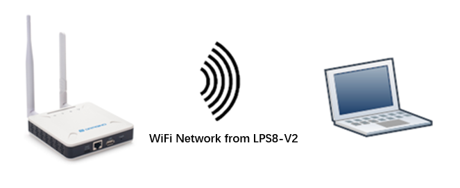
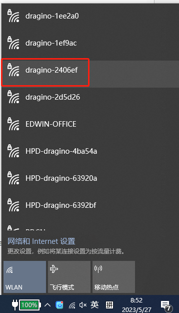
Since software version 230524,At the first boot of IM01-V2, it will auto generate a WiFi network called dragino-xxxxxx with password: dragino+dragino
User can use a PC to connect to this WiFi network. The PC will get an IP address 10.130.1.xxx and the IM01-V2 has the default IP 10.130.1.1
Method 2: Connect via Ethernet with DHCP IP from the router
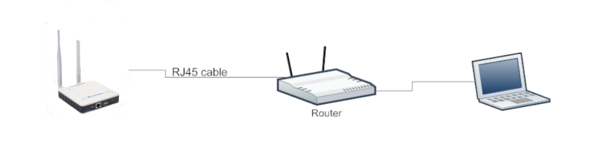
Connect the IM01-V2 Ethernet port to your router and IM01-V2 can obtain an IP address from your router. In the router's management portal, you should be able to find what IP address the router has assigned to the IM01-V2.
You can also use this IP to connect.
Method 3: Connect via IM01-V2 Fallback IP
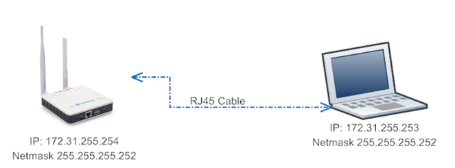
Steps to connect via fallback IP:
-
Connect the PC's Ethernet port to IM01-V2's WAN port
-
Configure PC's Ethernet port has IP: 172.31.255.253 and Netmask: 255.255.255.252
Settings --> Network & Internet --> Ethernet --> Change advanced sharing options --> Double-click"Ethernet" --> Internet Protocol Version 4 (TCP/IPv4)
As in the below photo:
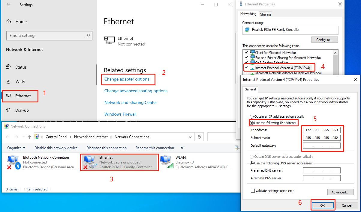
Configure computer Ethernet port steps video: fallback ip.mp4
If you still can't access the IM01-V2 fallback ip, follow this connection to debug : Trouble Shooting
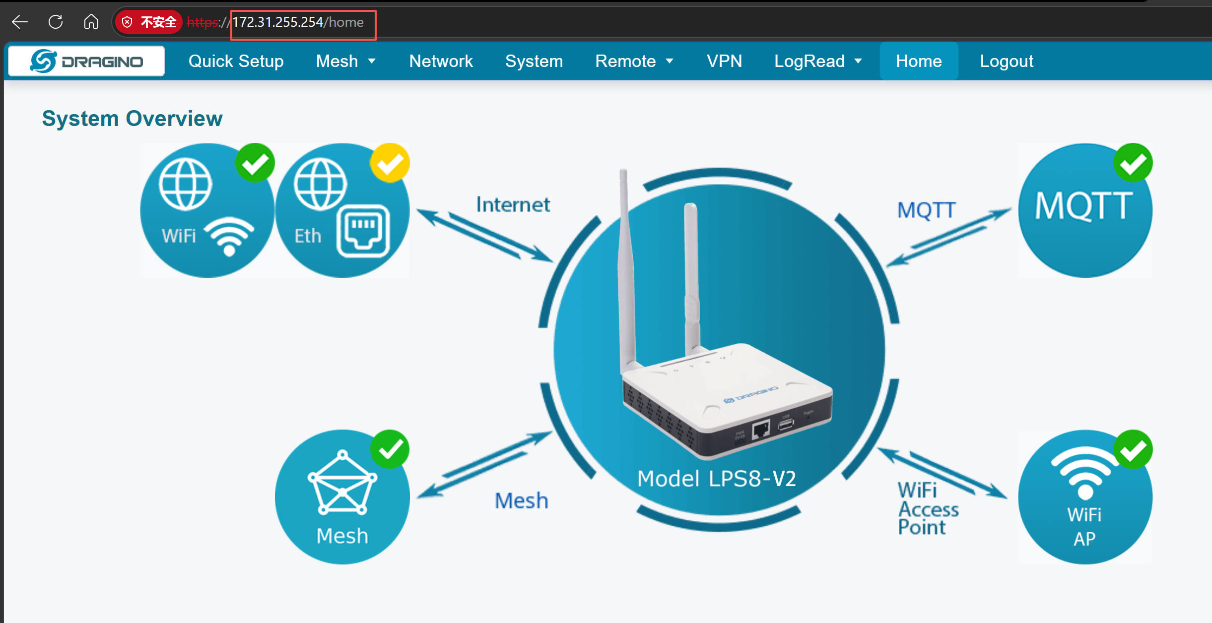
- In the PC, use IP address 172.31.255.254 to access the IM01-V2 via Web or Console.
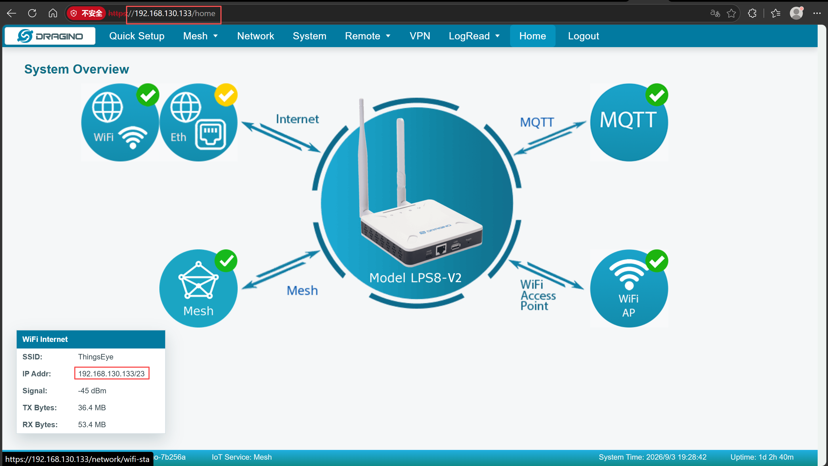
Method 4: Connect via WiFi with DHCP IP from the router
Fill in the WiFi information by checking the box and clicking Save&Apply
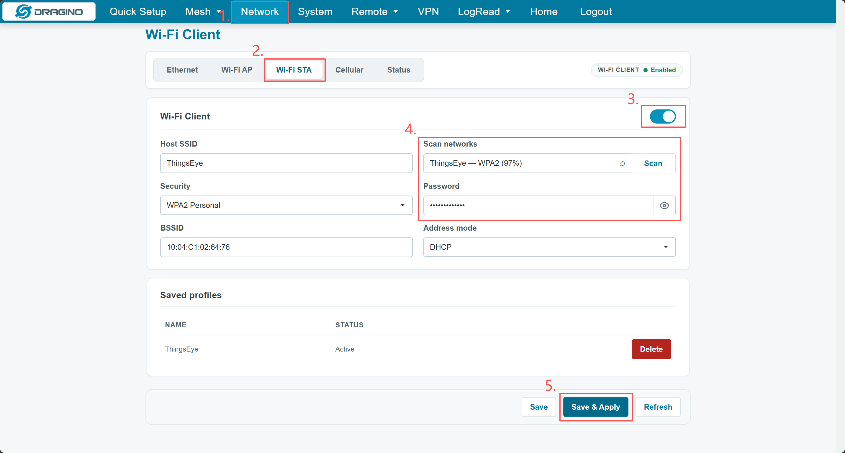
Wi-Fi configuration successful
2.1.2 Access Configure Web UI
Web Interface
Open a browser on the PC and type the IM01-V2 ip address (depends on your connect method)
Use http://IP_ADDRESS or http://172.31.255.254 (Fallback IP).
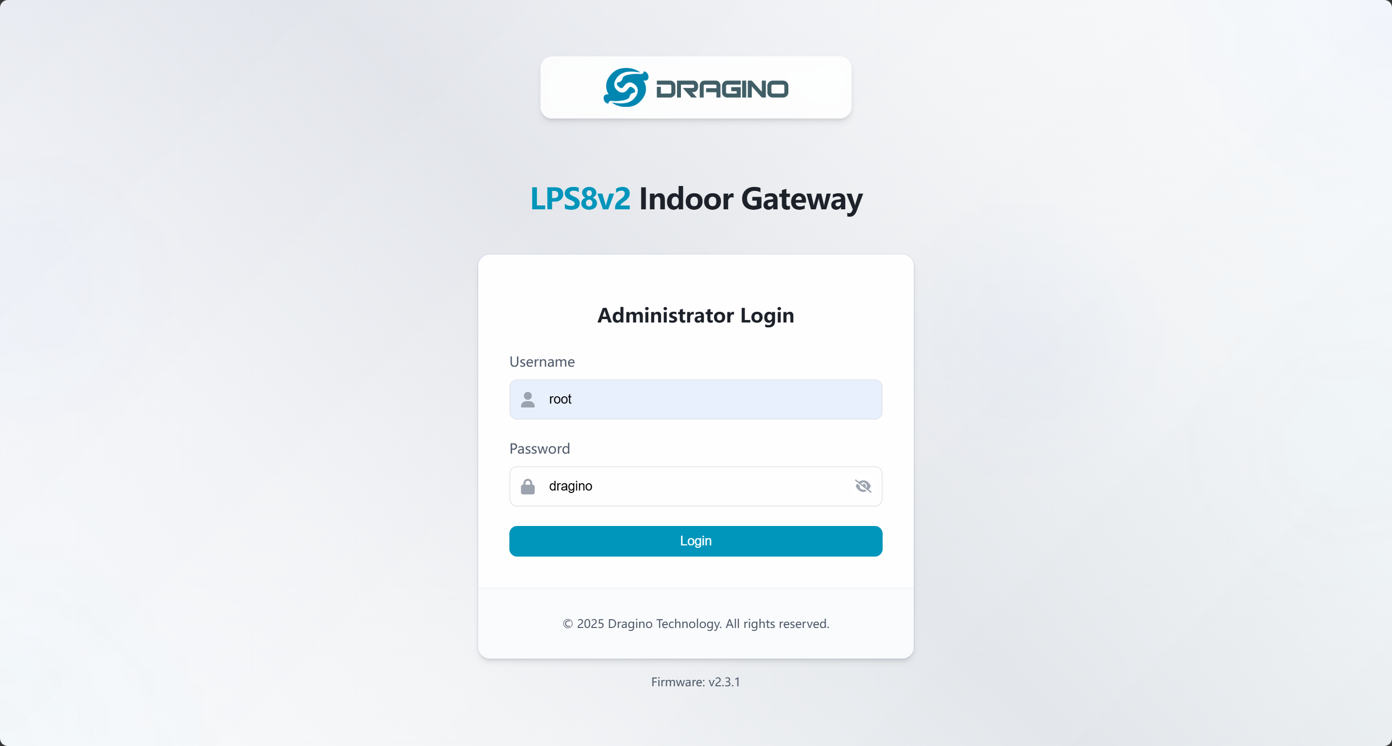
You will see the login interface of IM01-V2 as shown below.
The account details for Web Login are:
User Name: root Password: dragino
3. Quick Setup
3.1 Quick Setup Overview
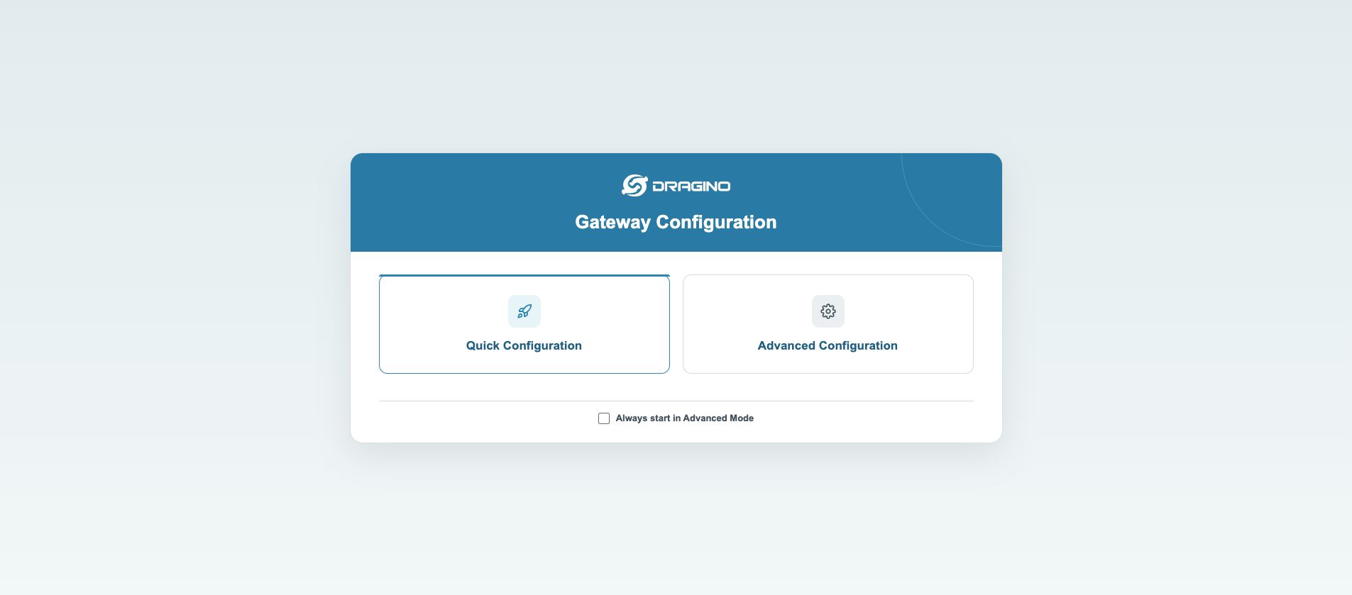
Go to /setup page and click Quick Configuration to start the wizard.
3.2 Quick Setup Wizard
Click Quick Configuration to launch the step-by-step wizard. Use the bottom buttons to control the wizard process:
Back/Next: Switch between setup pages.Exit: Quit the wizard at any time and return to the home page.Save & Apply: Take effect after modifying parameters. Exit will not reset configurations.
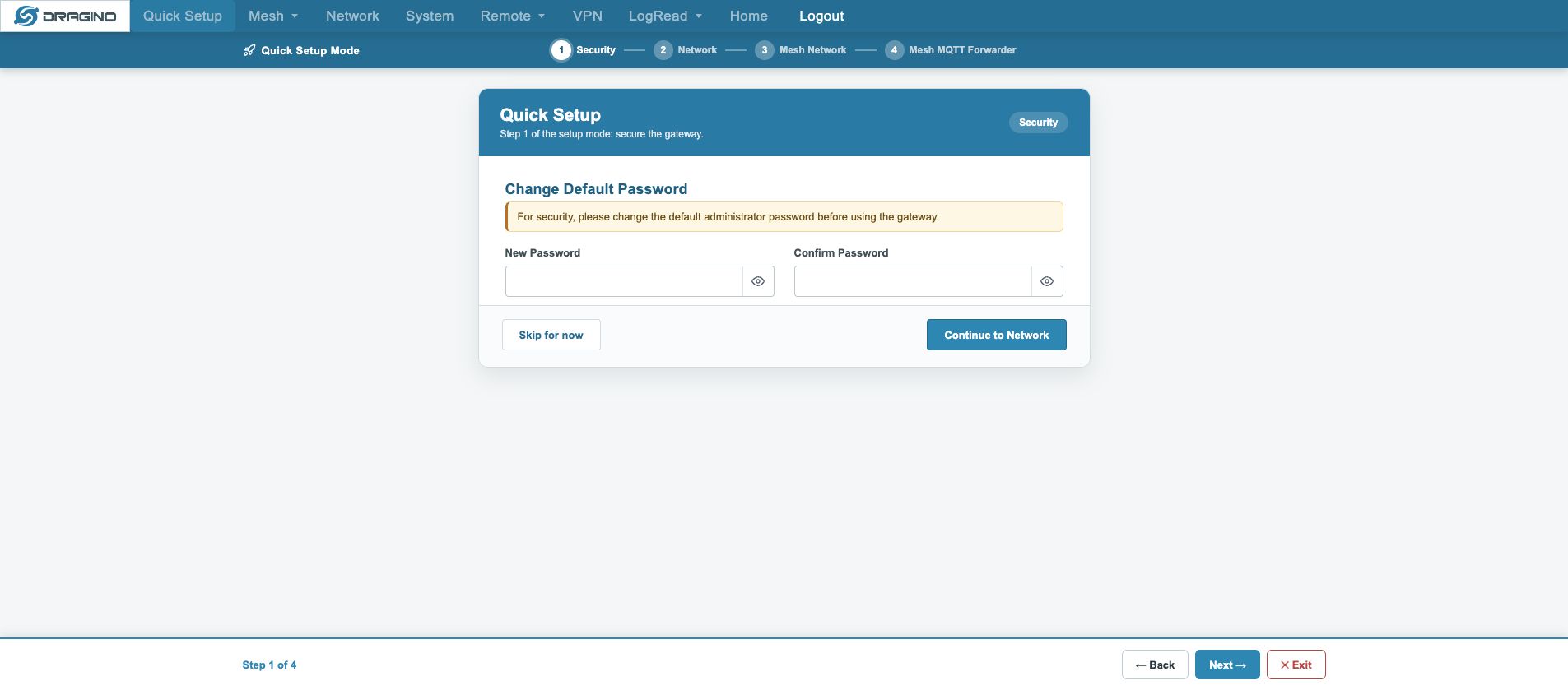
3.2.1 Security
Used to modify the gateway admin password.
- Set and confirm a new admin password, then click
Continue to Network. - Skip password modification by clicking
Skip for now.
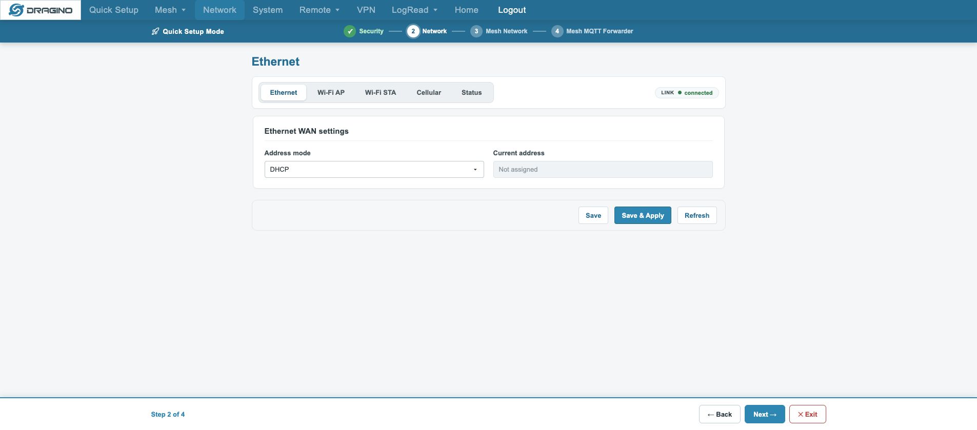
3.2.2 Network
Configure gateway uplink network access, including Ethernet, WiFi and cellular network.
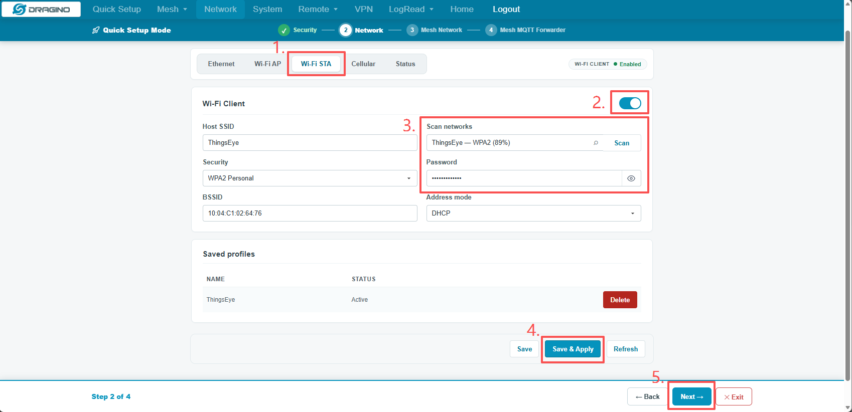
Take WiFi‑STA as an example to connect gateway to upstream WiFi:
- Select the
Wi‑Fi STAtab. - Enable the Wi‑Fi Client toggle switch.
- Click
Scanto discover nearby Wi‑Fi networks, select target SSID and enter Wi‑Fi password. - Click
Save & Applyto apply settings. - Wait until Wi‑Fi shows connected status, then click bottom
Nextfor next step.
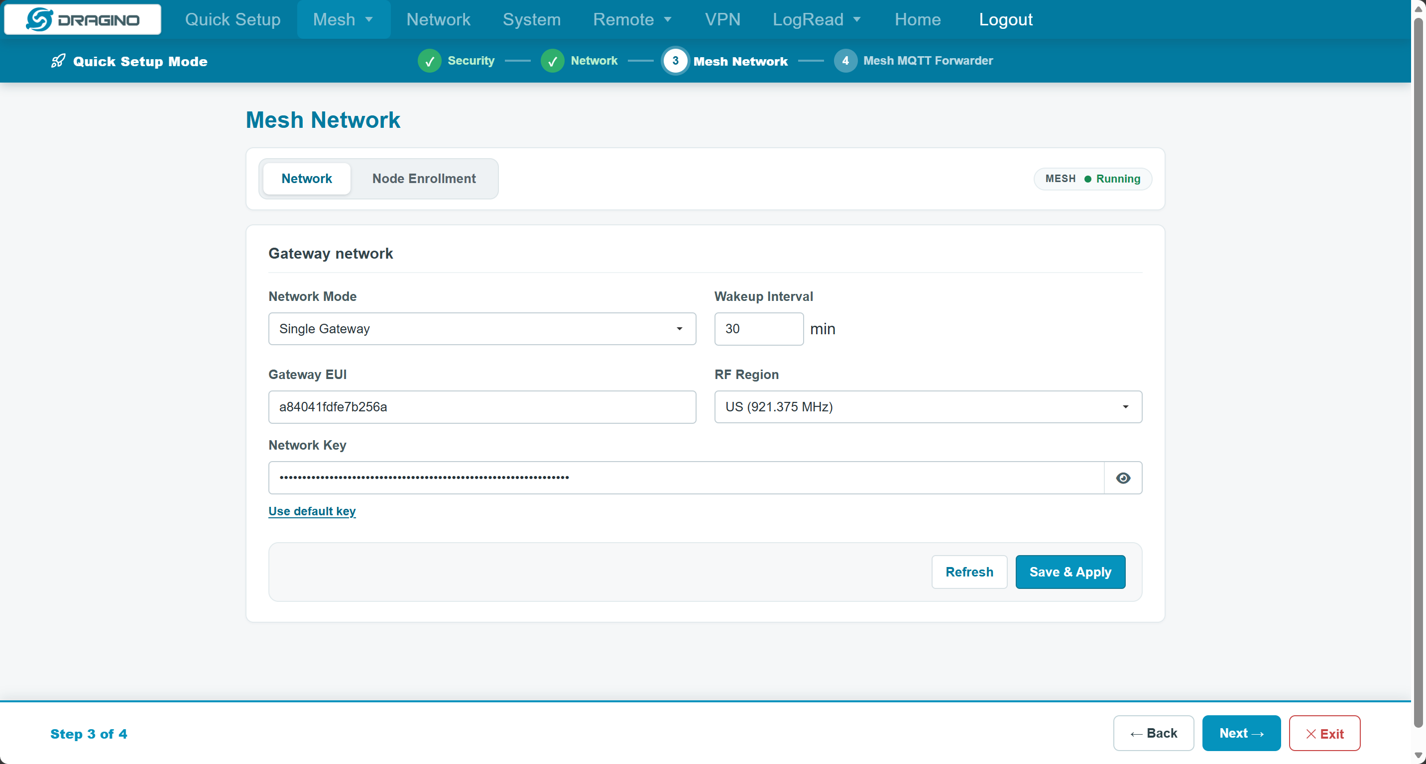
3.2.3 Mesh Network
Configure core Mesh network parameters to build LoRa Mesh multi-hop network. This example uses Single Gateway mode.
- Set
Network ModetoSingle Gateway. - Select the correct
RF Regionaccording to local radio regulations. - Use the default
Network Keyor customize a 64‑bit hexadecimal network key. - Click
Save & Apply. - Click
Nextto continue.
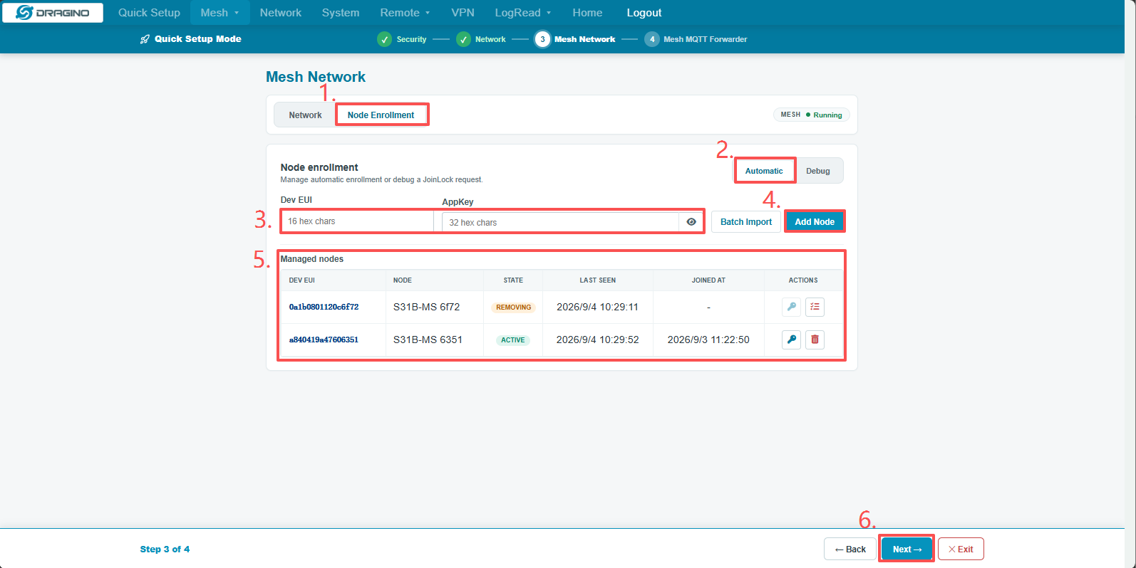
Switch to the Node Enrollment tab for fast node registration:
- Switch to the
Node Enrollmenttab. - Select
Automaticmode. - Fill in node
Dev EUI(16 hex chars) andAppKey(32 hex chars). - Click
Add Node. - Check and confirm node status and
Last Seenin theManaged nodeslist. - Click
Nextafter confirmation.
3.2.4 Mesh MQTT Forwarder
Configure Mesh data forwarding rules to upload Mesh node data to MQTT server.
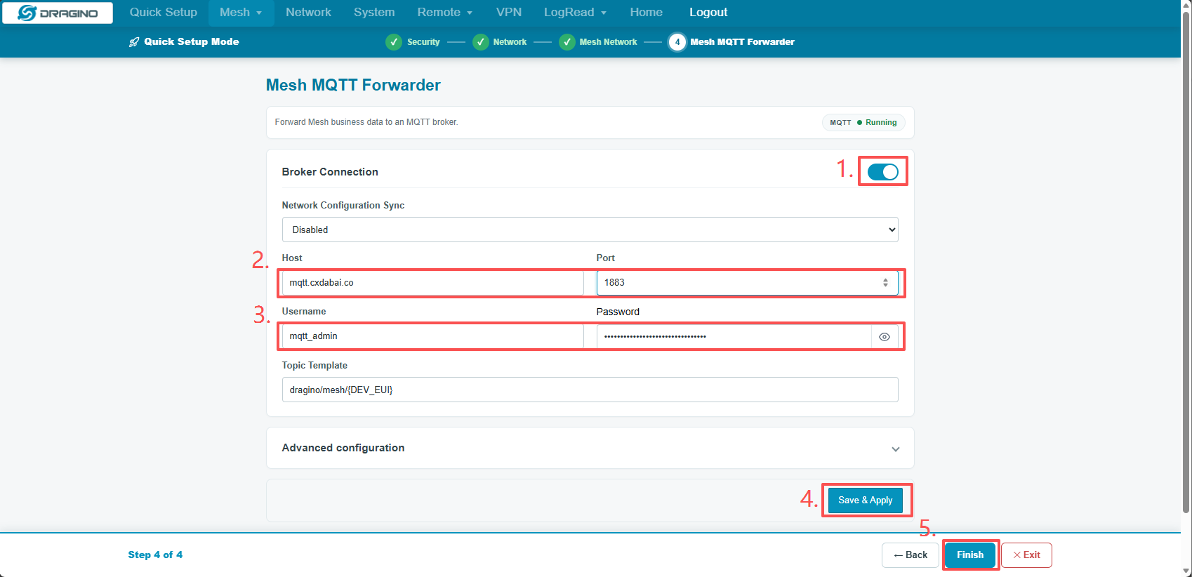
Option 1: Plain non‑TLS connection (Port 1883)
- Toggle on
Broker Connection. - Fill in MQTT server
Hostand set port to1883. - Enter MQTT
UsernameandPassword. - Keep default
Topic Template, clickSave & Apply. - Click
Finishto complete quick‑setup.
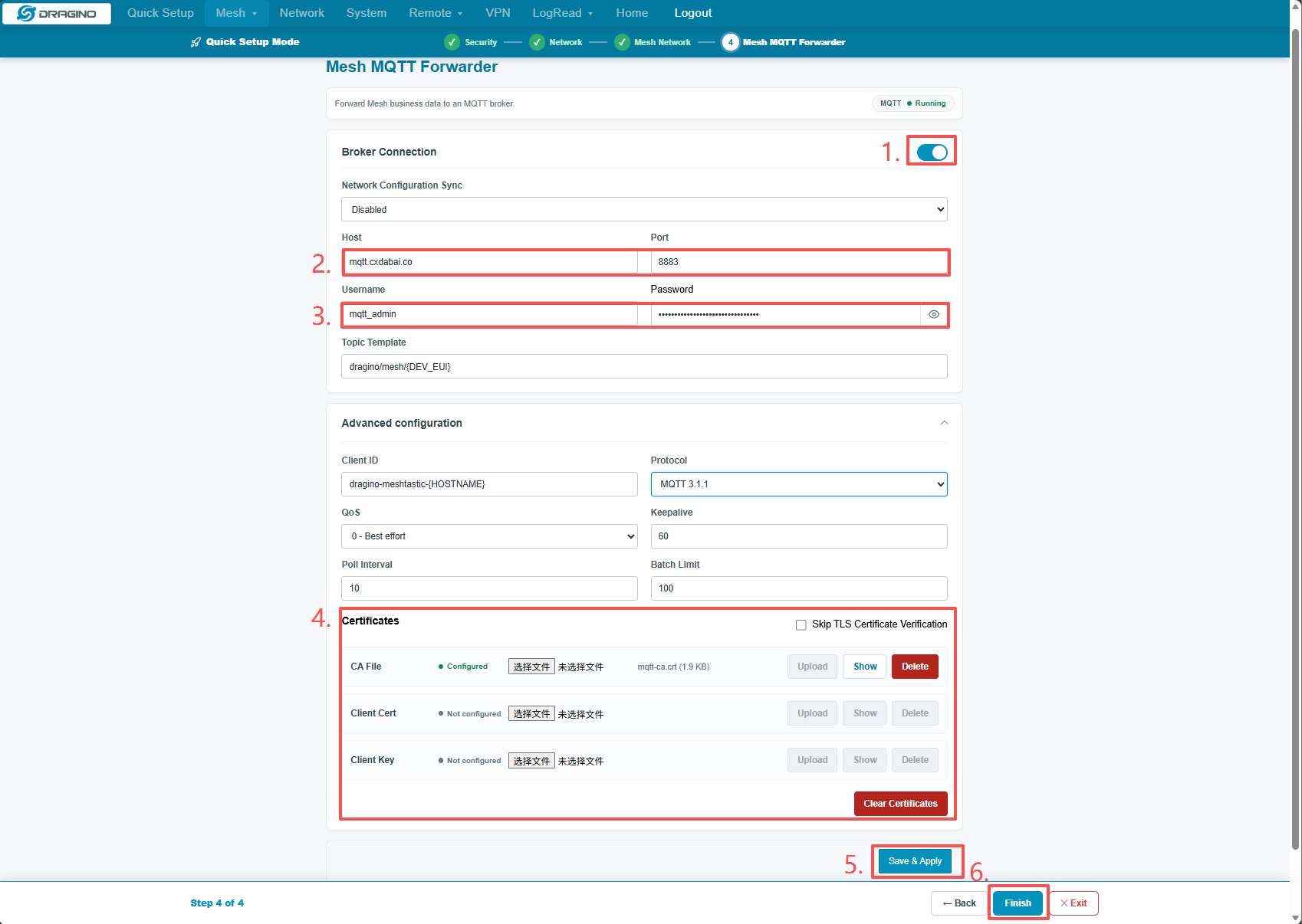
Option 2: TLS‑encrypted connection (Port 8883)
- Enable
Broker Connection. - Fill in the MQTT server
Host, set port to8883. - Enter the MQTT broker
UsernameandPassword. - Expand
Advanced configuration, upload CA file, client certificate and client private key under Certificates section. - Click
Save & Apply. - Click
Finishto complete the entire quick‑setup process.
4 Mesh Network Deployment and Advanced Configuration
This chapter describes the complete Mesh gateway deployment flow.
4.1 Preparation
Prepare the RF Region, Network Mode, Network Key, node Dev EUI and AppKey. For MQTT, also prepare the Broker, port, credentials, Topic and TLS files.
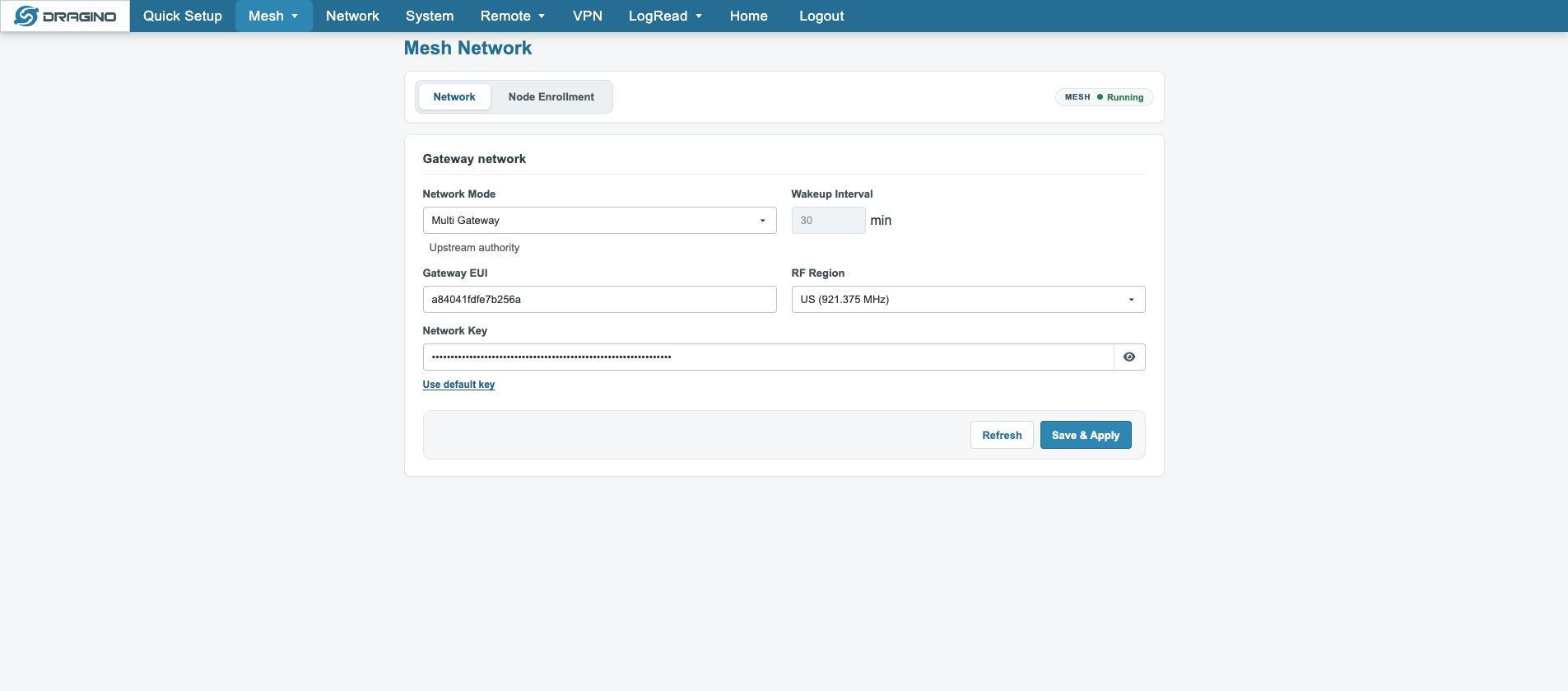
4.2 Mesh network parameters
Path: Mesh → Mesh Network → Network.
| Parameter | Meaning |
|---|---|
| Network Mode | Single Gateway or Multi Gateway |
| Wakeup Interval | Node or gateway wake-up interval in minutes |
| Gateway EUI | Gateway identity; do not change without a plan |
| RF Region | Must match the deployment region and nodes |
| Network Key | Mesh network key; changing it may disconnect existing nodes |
Apply the change, wait for services to recover, then refresh and verify. Do not power off or repeatedly click during application.
4.3 Single Gateway
The local gateway controls the Mesh network and nodes. It is suitable for an independent deployment:
Configure Mesh Network → Add node → Wait for Join → Verify Mesh Data
4.4 Multi Gateway
Multi Gateway is used when several gateways share a Mesh network configuration. An upstream configuration source may become authoritative and local fields may be locked. Check Network Configuration Sync, Network Scope and the upstream publication status instead of forcing disabled fields.
4.5 Node enrollment and removal
(1) Automatic: use it for a node with a known Dev EUI and AppKey.
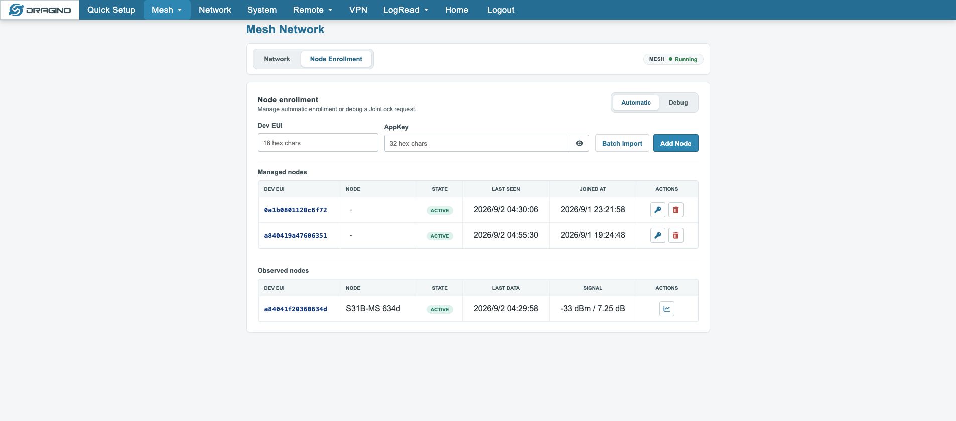
(2) Batch Import: import multiple Dev EUI/AppKey pairs from CSV. Verify the saved count and Managed nodes afterward.
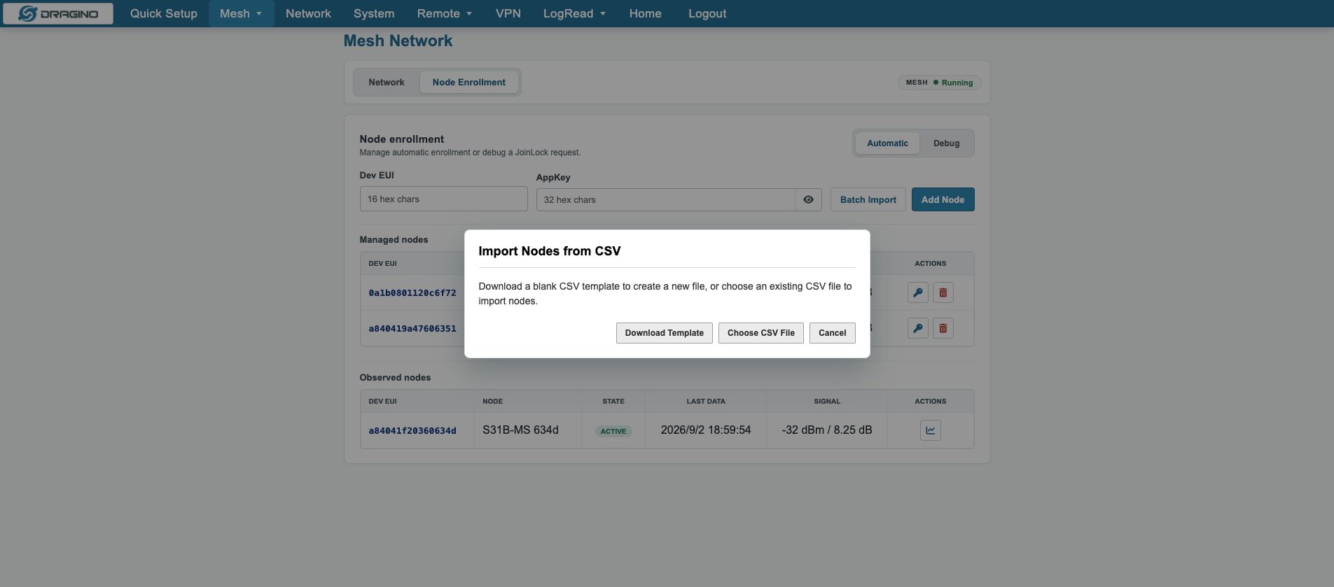
(3) Debug: use it to accept a JoinLock discovered at the site.
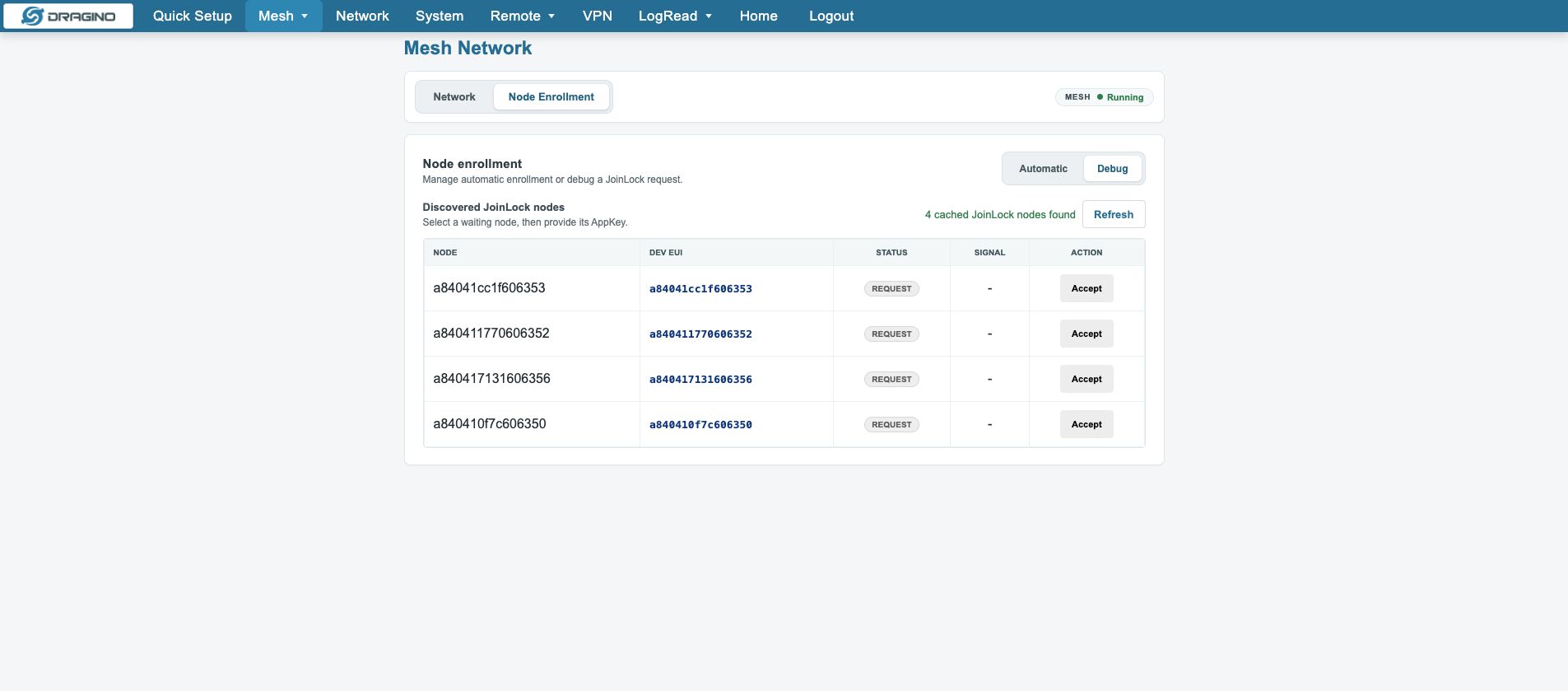
Node state reference:
Managed node: local preconfiguration exists
Observed node: the wireless side has seen the node
Active: recent activity exists
Mesh Data: business records exist
These states are not equivalent. Node removal offers Wait for remote unenrollment and Clean gateway state now. The latter only cleans gateway state and does not erase the node remotely.
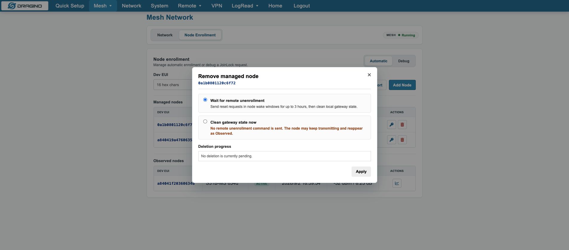
4.6 Data verification
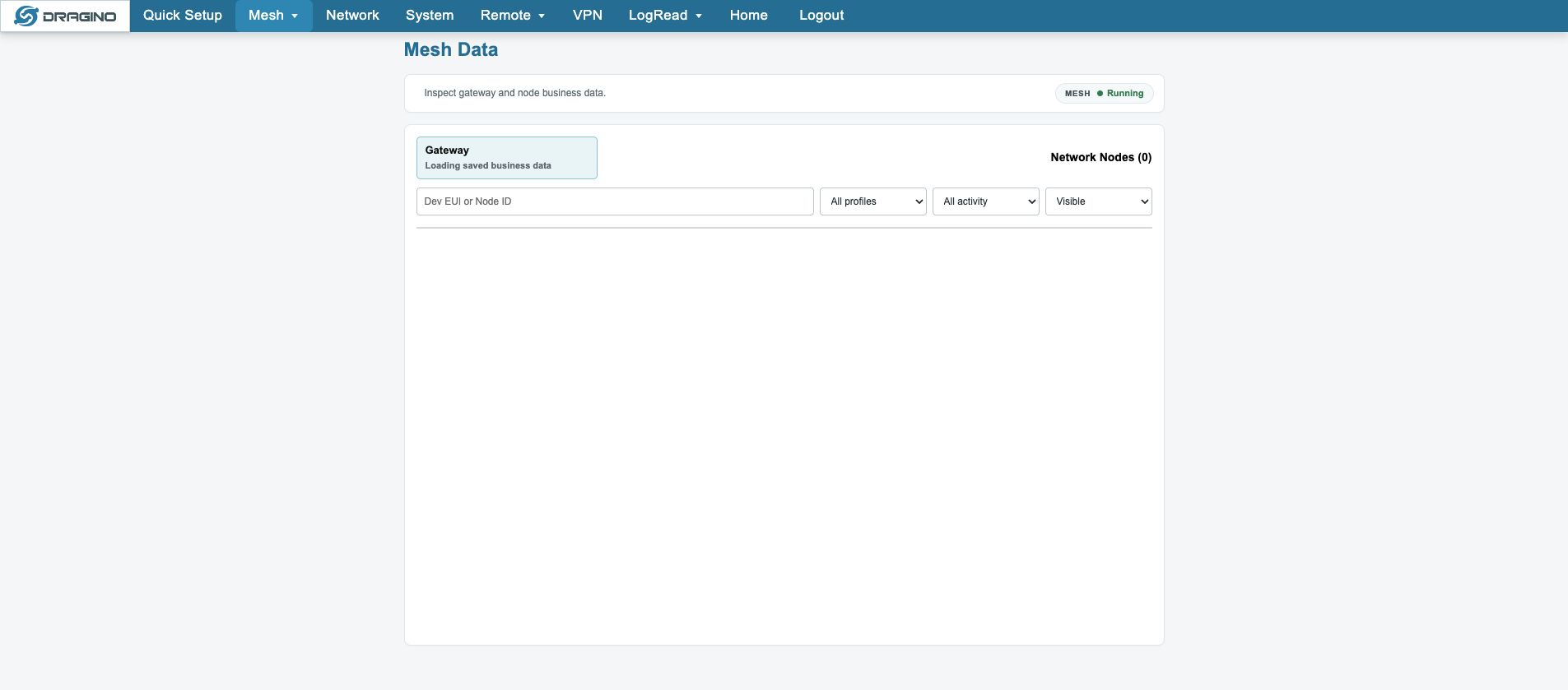
After enrollment, open Mesh → Mesh Data. Confirm that the node appears, then open its Data History and business JSON.
Managed contains the target Dev EUI
→ State becomes joined/active
→ Last Seen updates
→ Observed contains the node
→ Mesh Data finds the node
→ Data History contains a business record
→ Business JSON contains a valid payload or values
4.7 MQTT configuration and verification
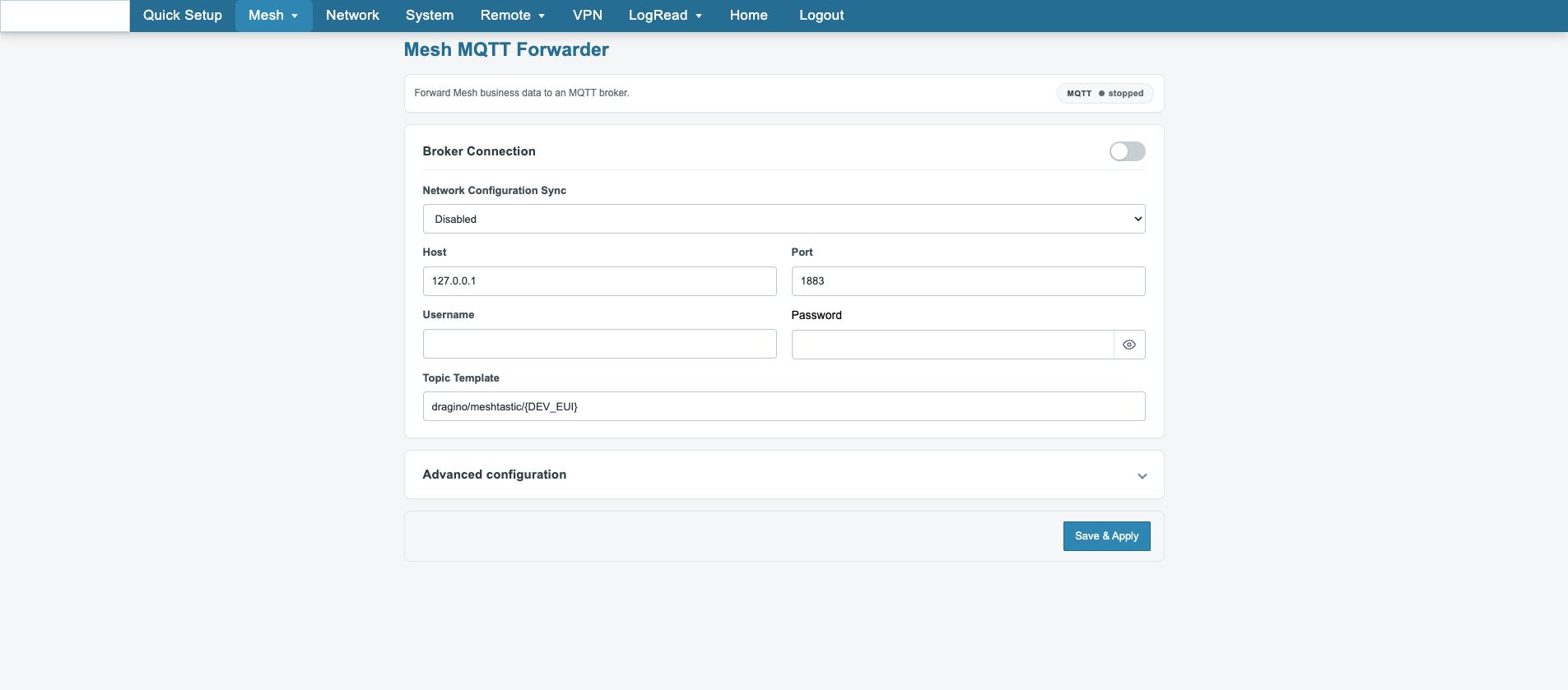
Open Mesh → Mesh MQTT Forwarder and follow these steps:
- Enable Enable MQTT Forwarder.
- Enter the Broker Host and Port.
- Enter Username and Password when required.
- Set Topic Template and keep a node identity such as
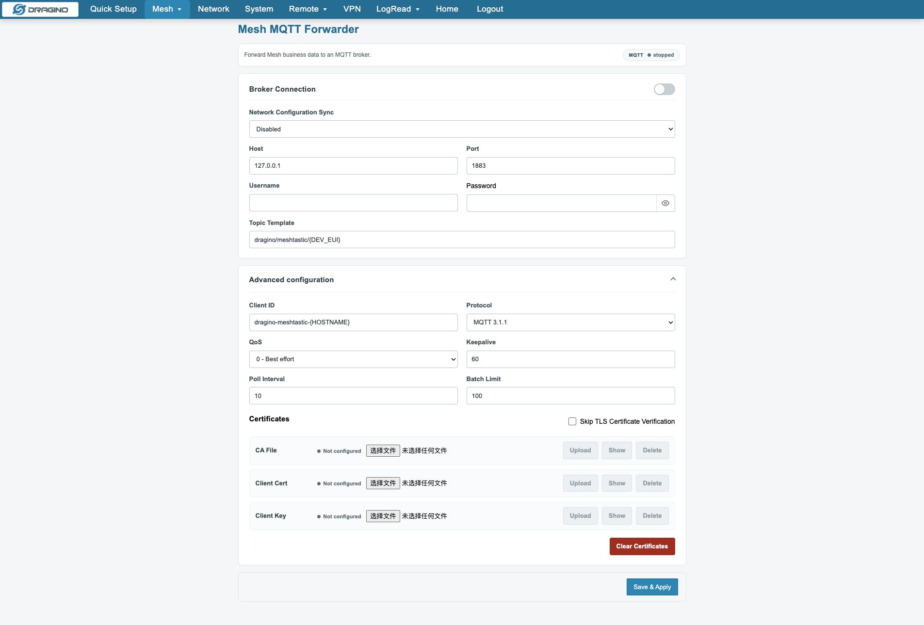
{BUSINESS_DEV_EUI},{BUSINESS_NODE_ID}or{OUTBOX_ID}. - Upload a CA File for TLS; upload both Client Cert and Client Key for mutual TLS.
- Use Advanced configuration for Client ID, Protocol, QoS, Keepalive, Poll Interval and Batch Limit.
- Confirm every uploaded certificate shows
Configured, then clickSave & Apply. - Check the Forwarder in System Overview, subscribe to the rendered Topic at the Broker, and verify the payload.
MQTT uses at-least-once delivery. Consumers should deduplicate with OUTBOX_ID, the business packet ID or a composite key.
5. Web Configure Pages
This chapter is a short page reference. It does not repeat the full deployment procedure.
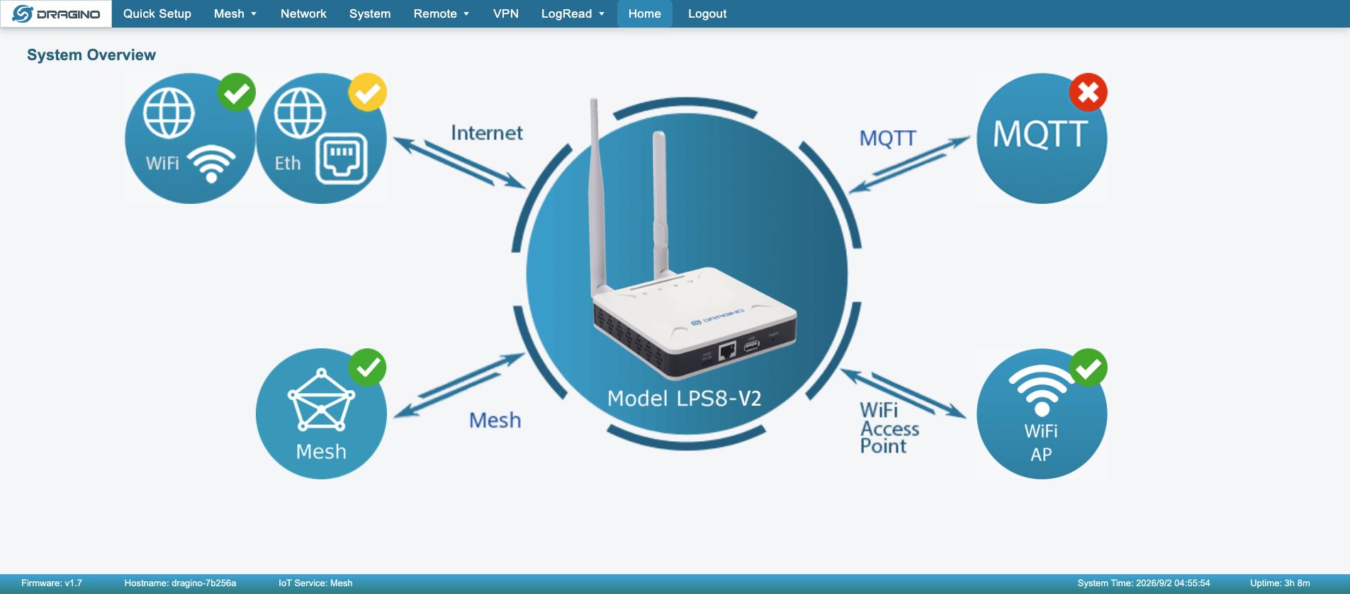
5.1 Home
Shows the device, network, Mesh and service overview.
5.2 Quick Setup
Provides quick‑configuration and advanced‑configuration modes.
Quick‑configuration guides Security, Network, Mesh Network and Mesh MQTT Forwarder setup.
5.3 Mesh
5.3.1 Mesh Network
Configures Mesh mode, wake-up interval, Gateway EUI, RF Region and Network Key.
5.3.2 Node Enrollment
Adds, imports, accepts or removes Mesh nodes.
5.3.3 Mesh Data
Shows gateway data, nodes, history and business JSON.
5.3.4 Mesh MQTT Forwarder
Sends existing Mesh business data to an MQTT Broker.
5.4 Network
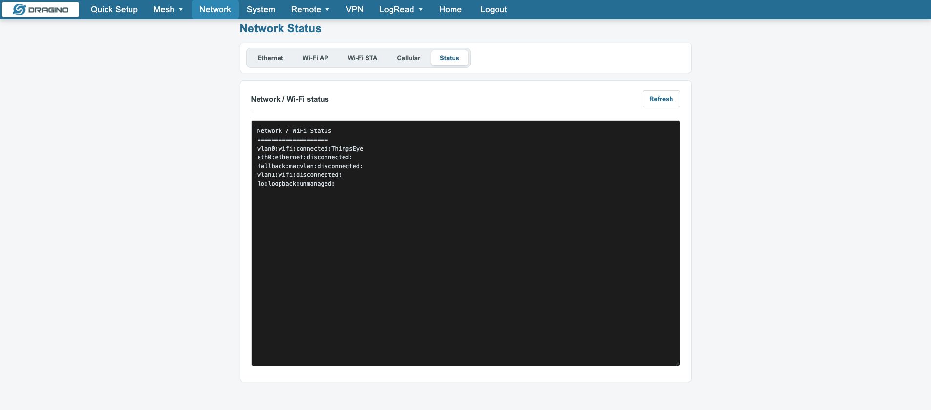
5.4.1 Network Status
Shows interfaces, addresses, default route and Internet state.
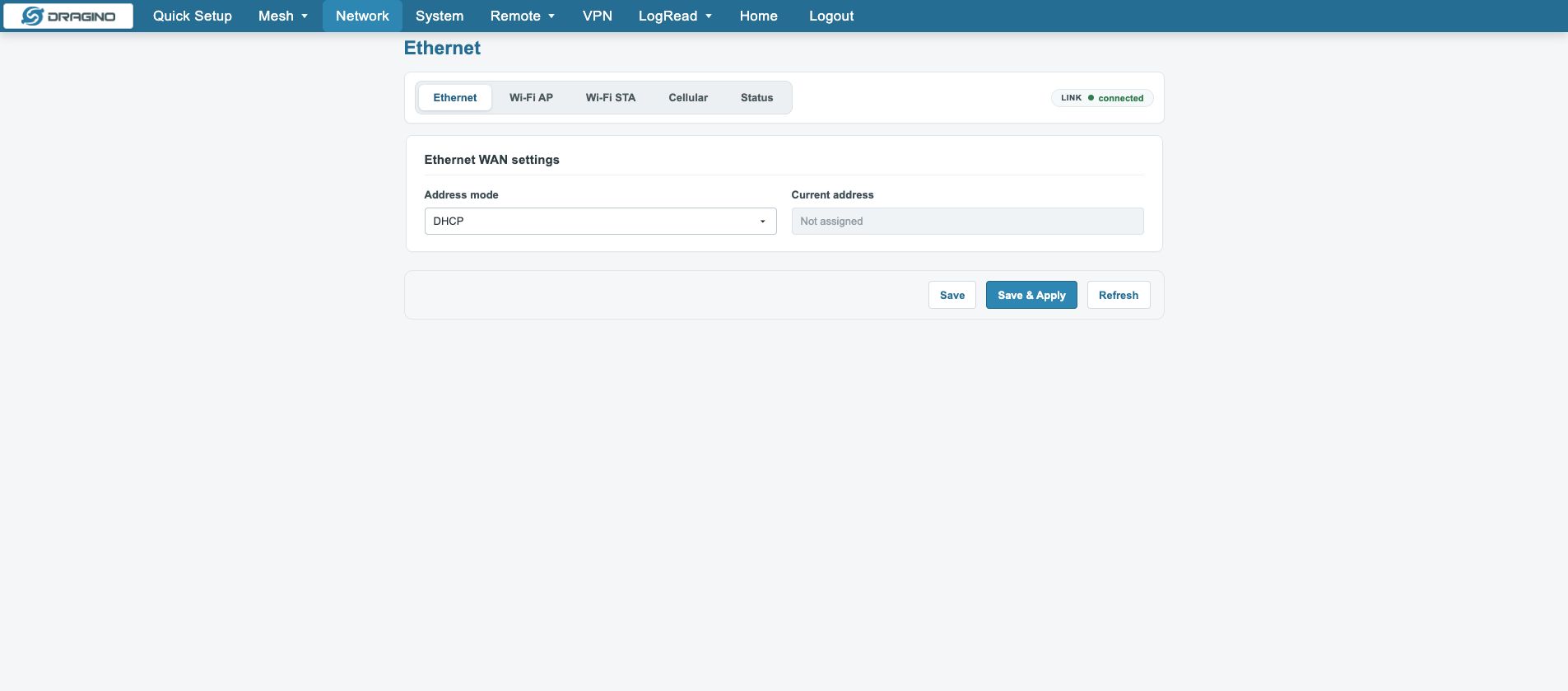
5.4.2 Ethernet
Configures DHCP or Static Ethernet.
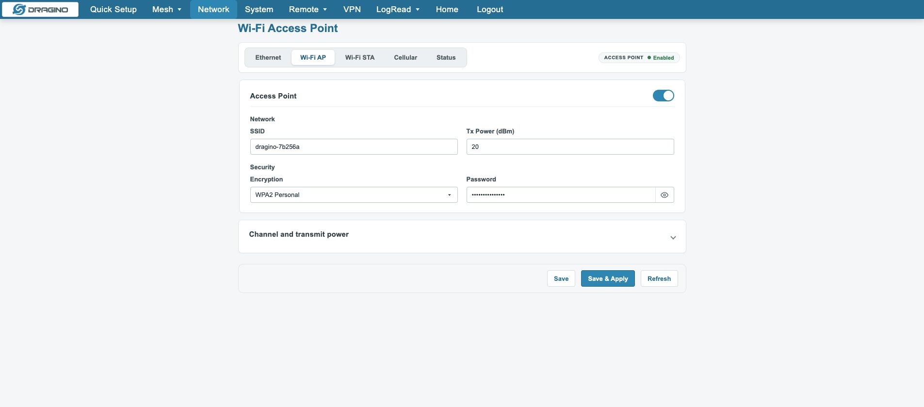
5.4.3 Wi-Fi AP
Configures the local management access point.
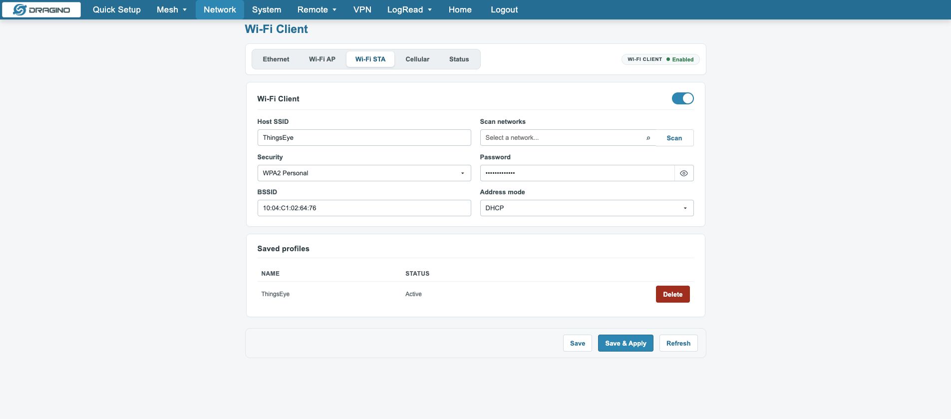
5.4.4 Wi-Fi STA
Configures an upstream Wi-Fi client.
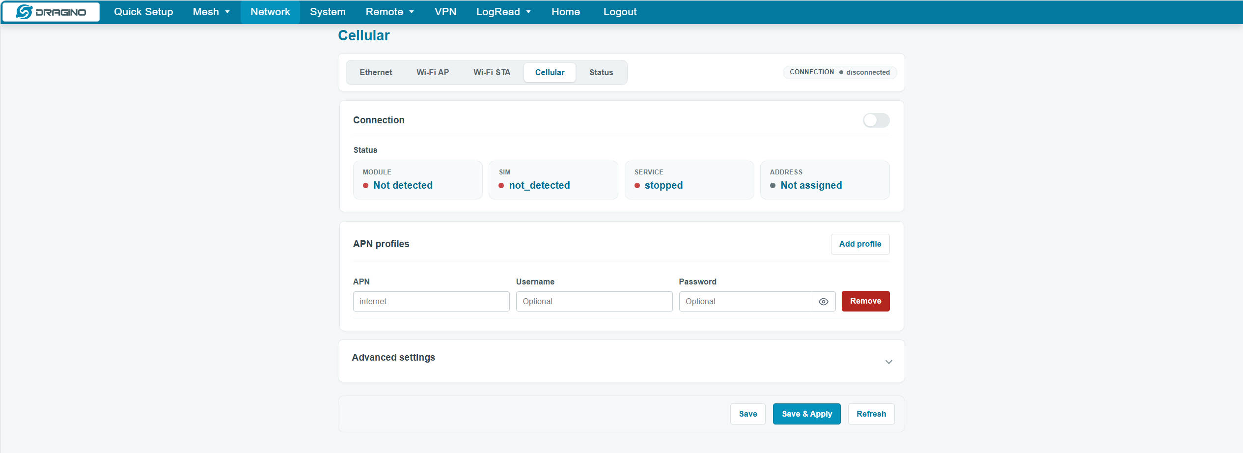
5.4.5 Cellular
Configures the cellular modem, SIM and APN.
5.5 System
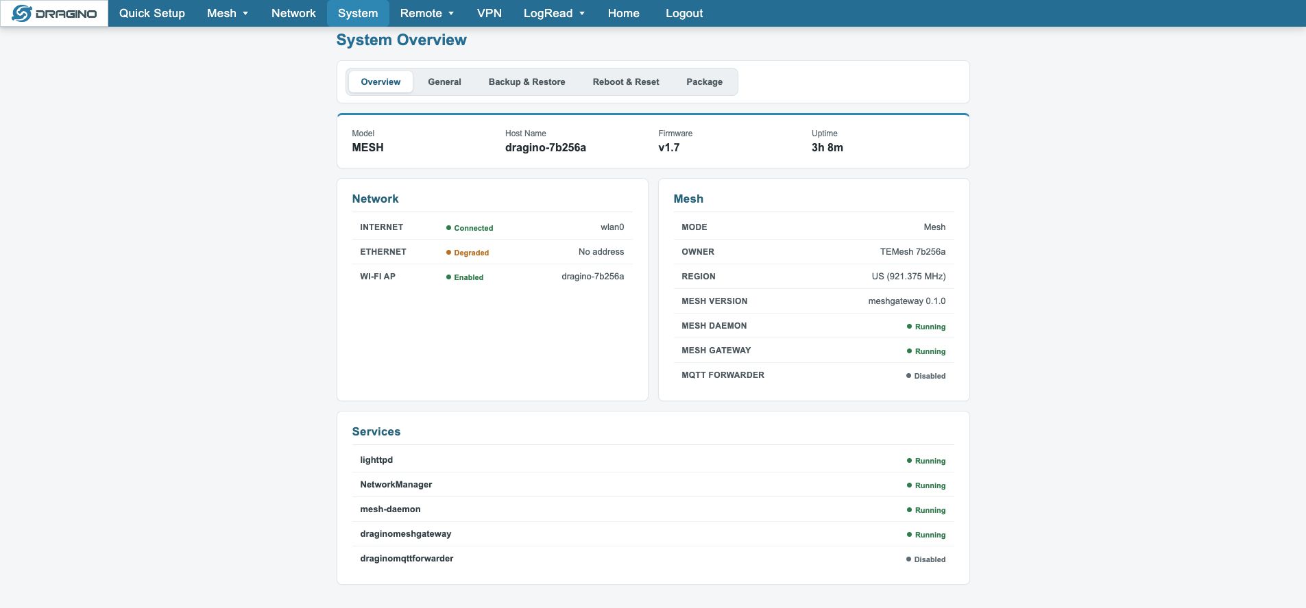
5.5.1 System Overview
Shows device, network, Mesh and service status.
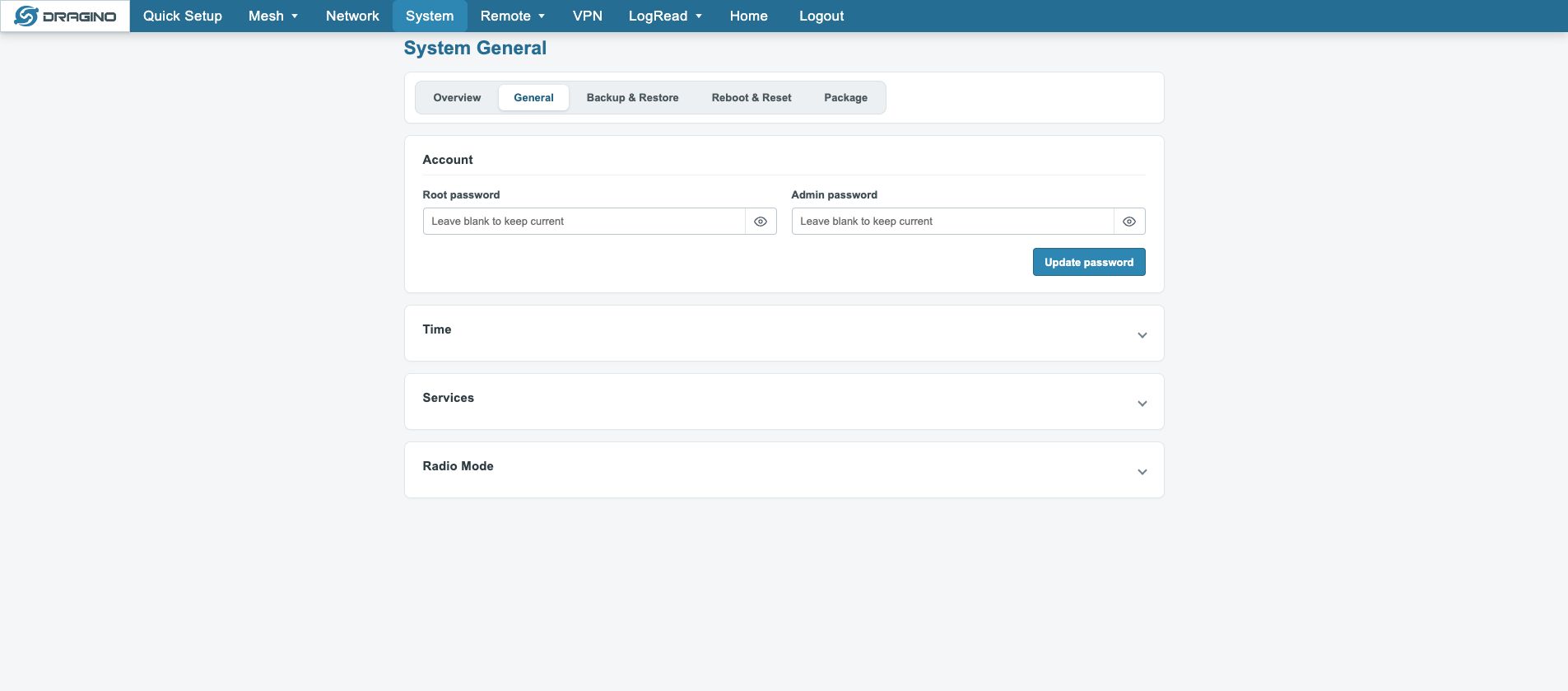
5.5.2 General
Configures accounts, time, services and Radio Mode.
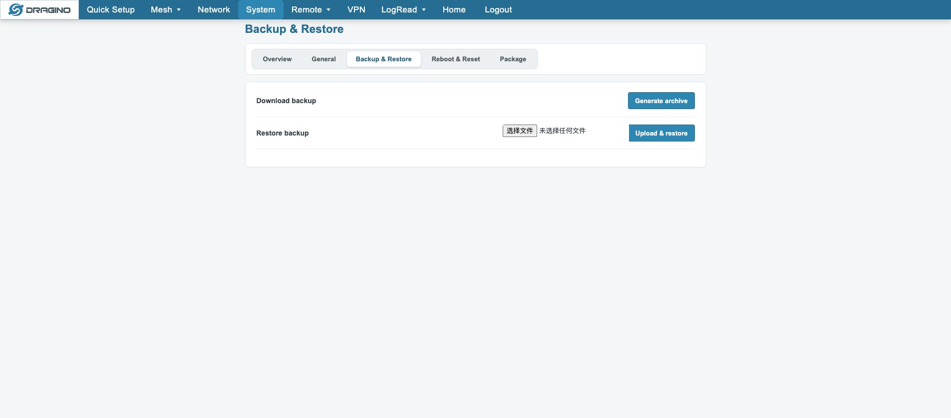
5.5.3 Backup and Restore
Creates or restores a configuration backup.
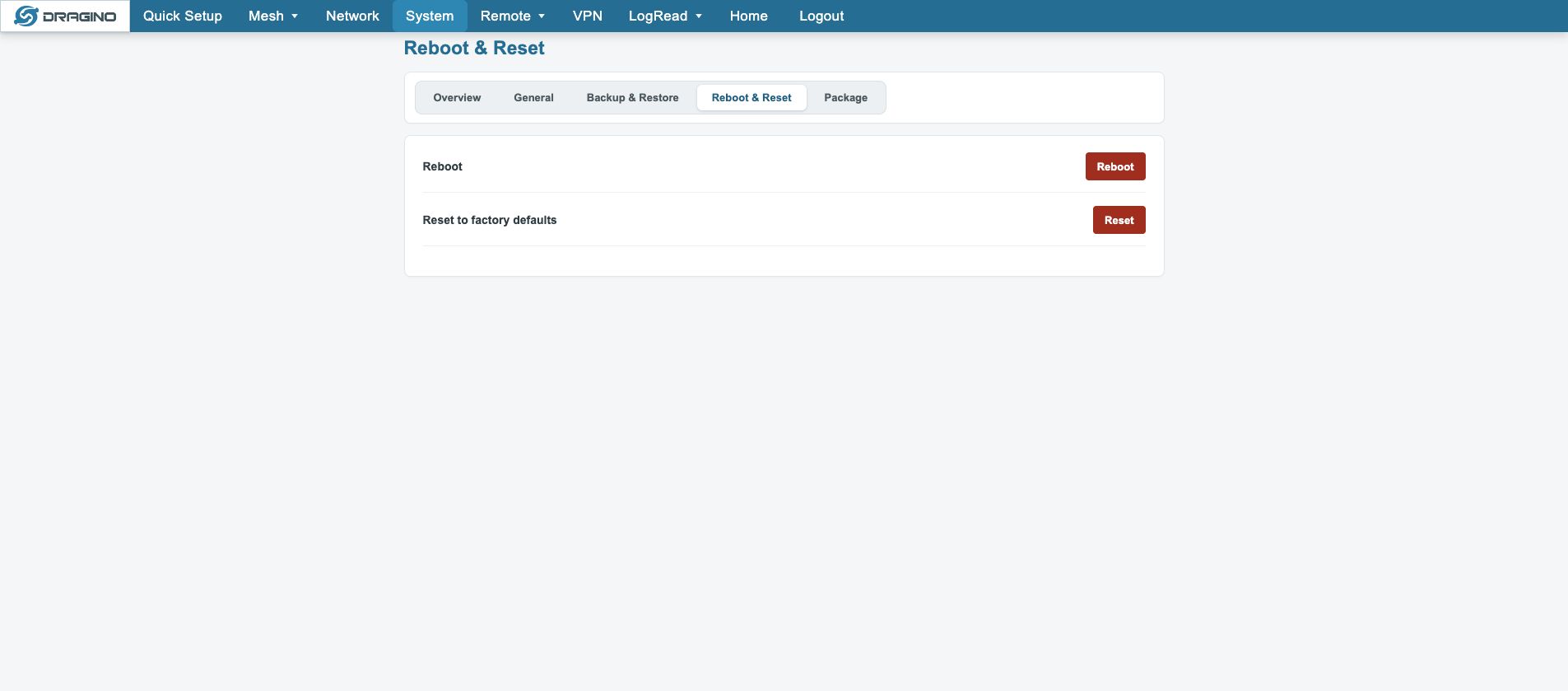
5.5.4 Reboot and Reset
Reboots or factory-resets the gateway. Back up before Reset.
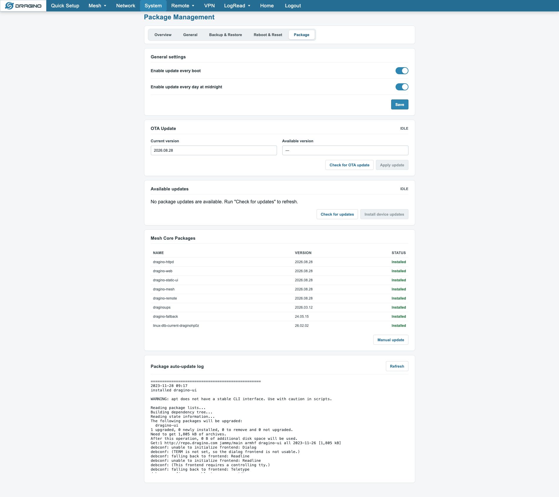
5.5.5 Package Management
Shows package versions and update status.
5.6 Remote
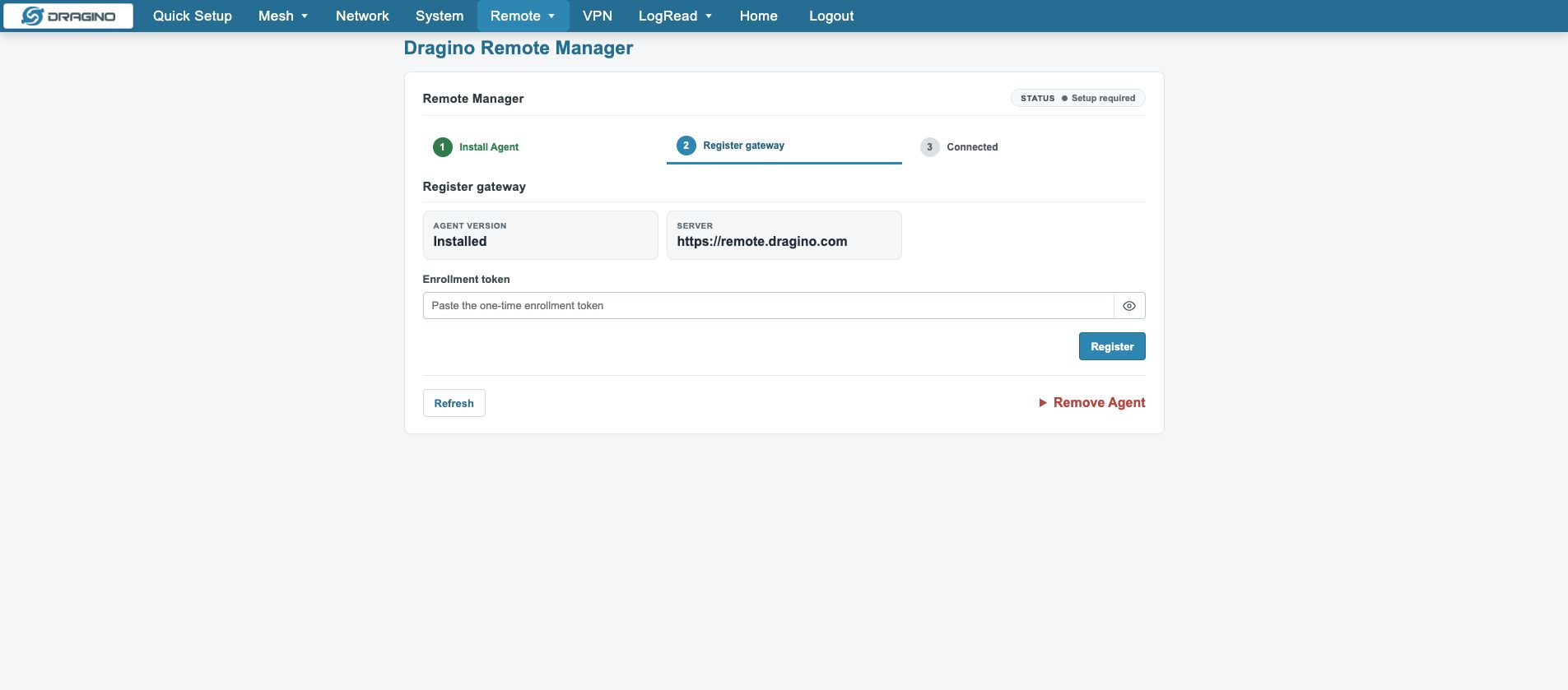
5.6.1 Dragino Remote Manager
Dragino Remote Manager is the built-in remote management channel.
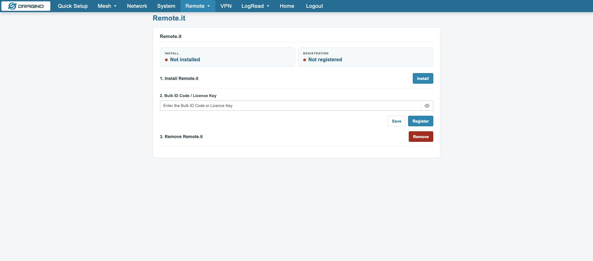
5.6.2 Remote.it
Remote.it is the third-party remote tunnel management platform.
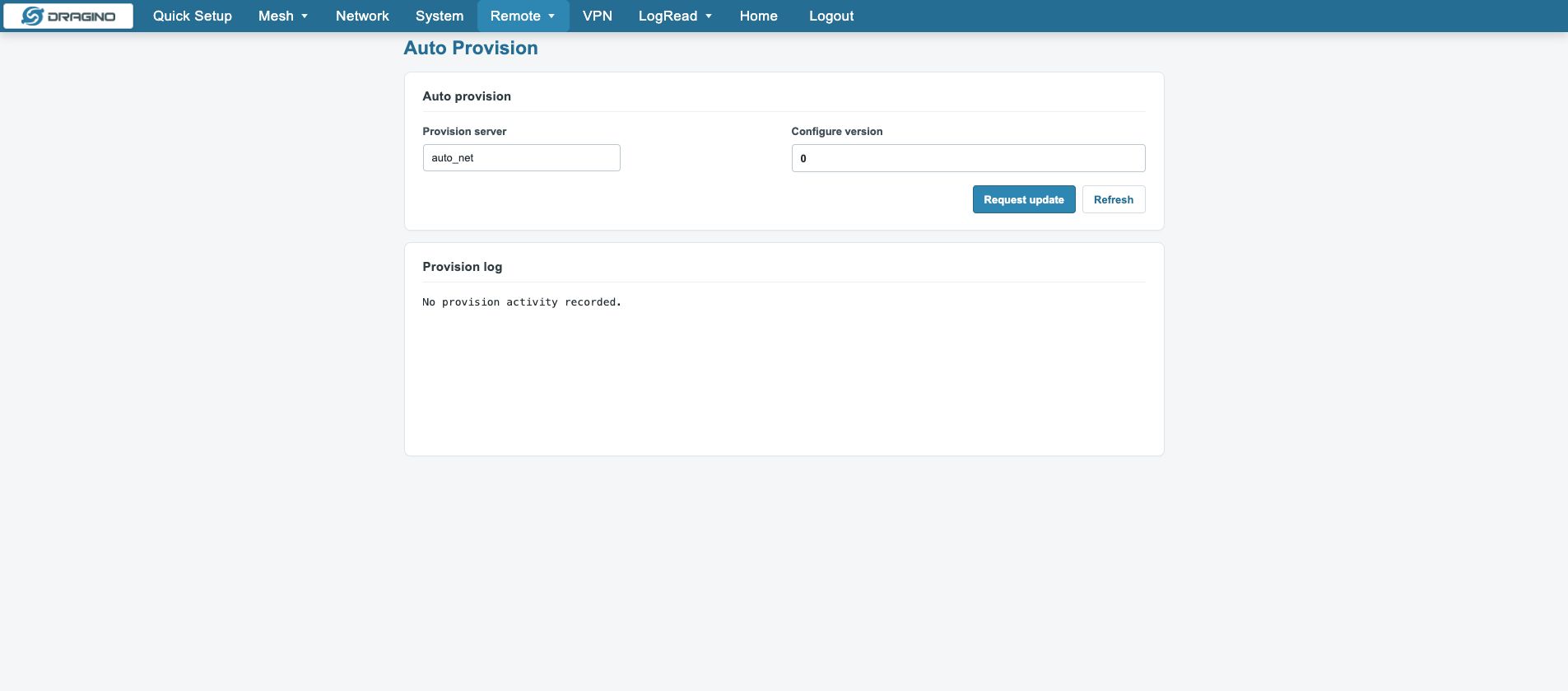
5.6.3 Auto Provision
Auto Provision pulls configuration from the configuration server.
5.7 VPN
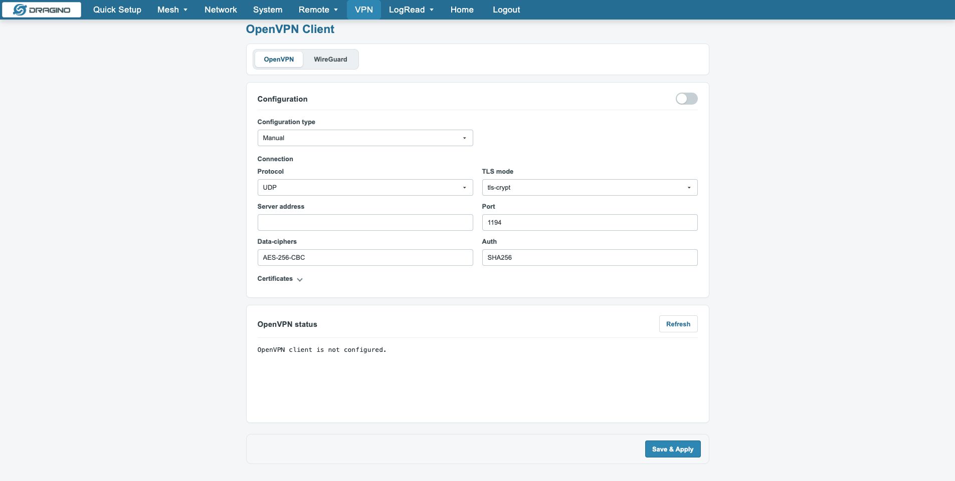
5.7.1 OpenVPN
Configures OpenVPN tunnels for encrypted remote access.
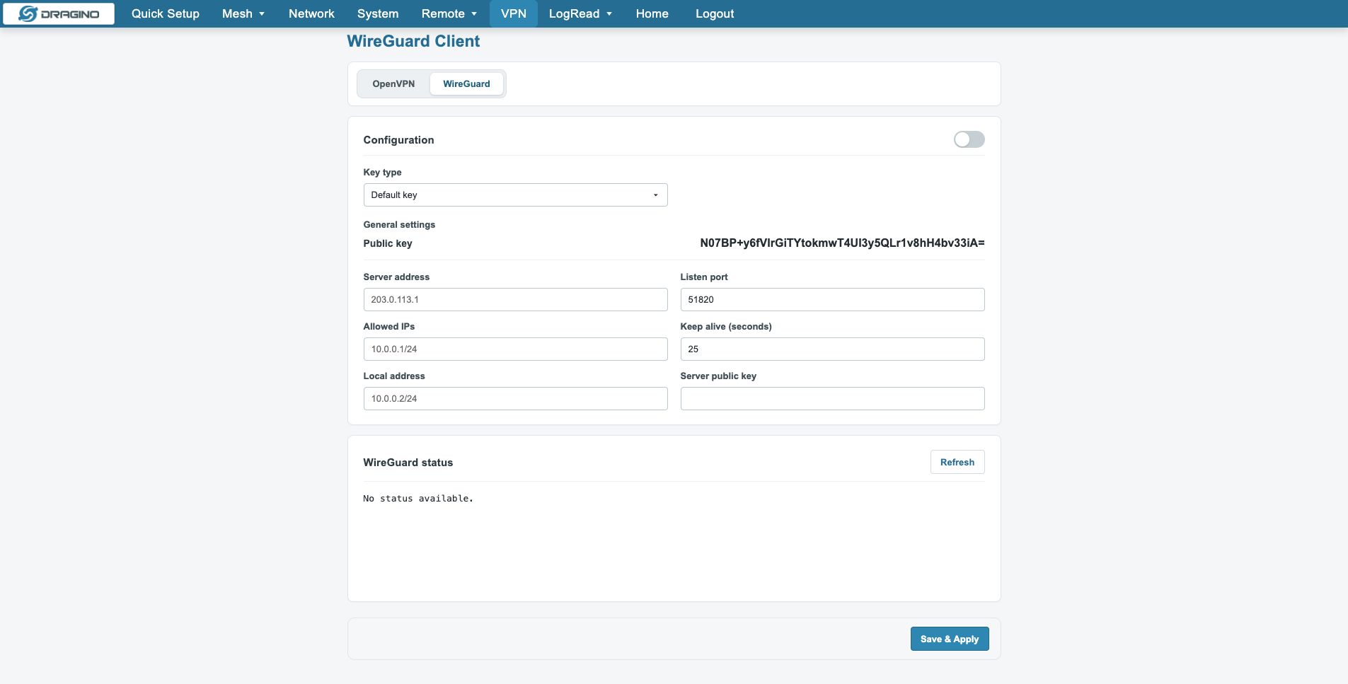
5.7.2 WireGuard
Configures WireGuard tunnels for lightweight fast‑speed VPN links.
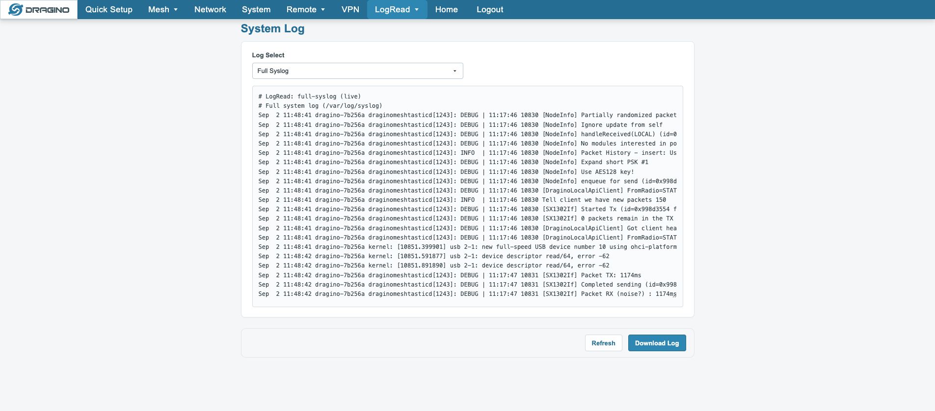
5.8 LogRead
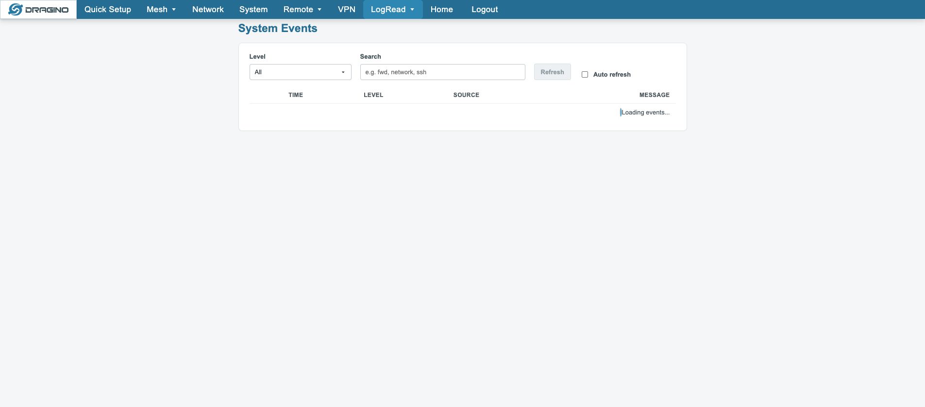
Shows Mesh Service State, Mesh Daemon, Mesh Gateway, MQTT Forwarder, System Log and Events.
6. Mesh Data and MQTT Operations
6.1 Gateway View
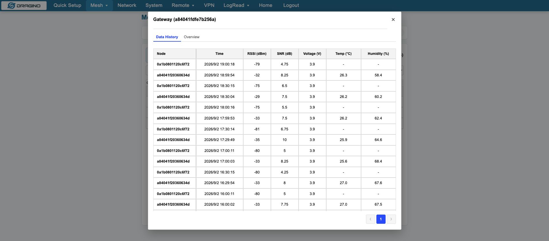
The Gateway view shows Saved Packets, Latest Data, Current/Historical Nodes, Packets per day, Packets by Node and gateway-wide Data History.
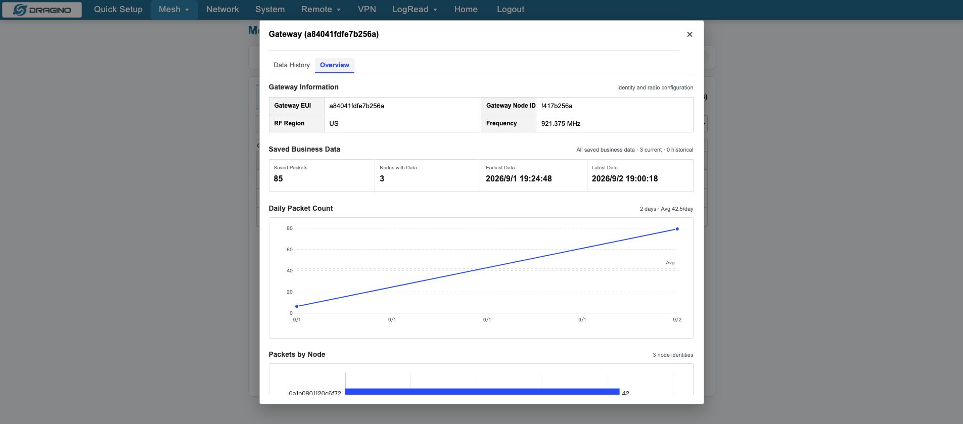
Open Data History to inspect business records from all nodes by time. Current/Historical usually uses the latest business-data time and is not the same as Managed/Observed state.
6.2 Network Nodes
Network Nodes shows Node, Dev EUI, State, Node ID, RSSI, SNR and Last Seen. Filters cover identity, profile type, activity and visibility.
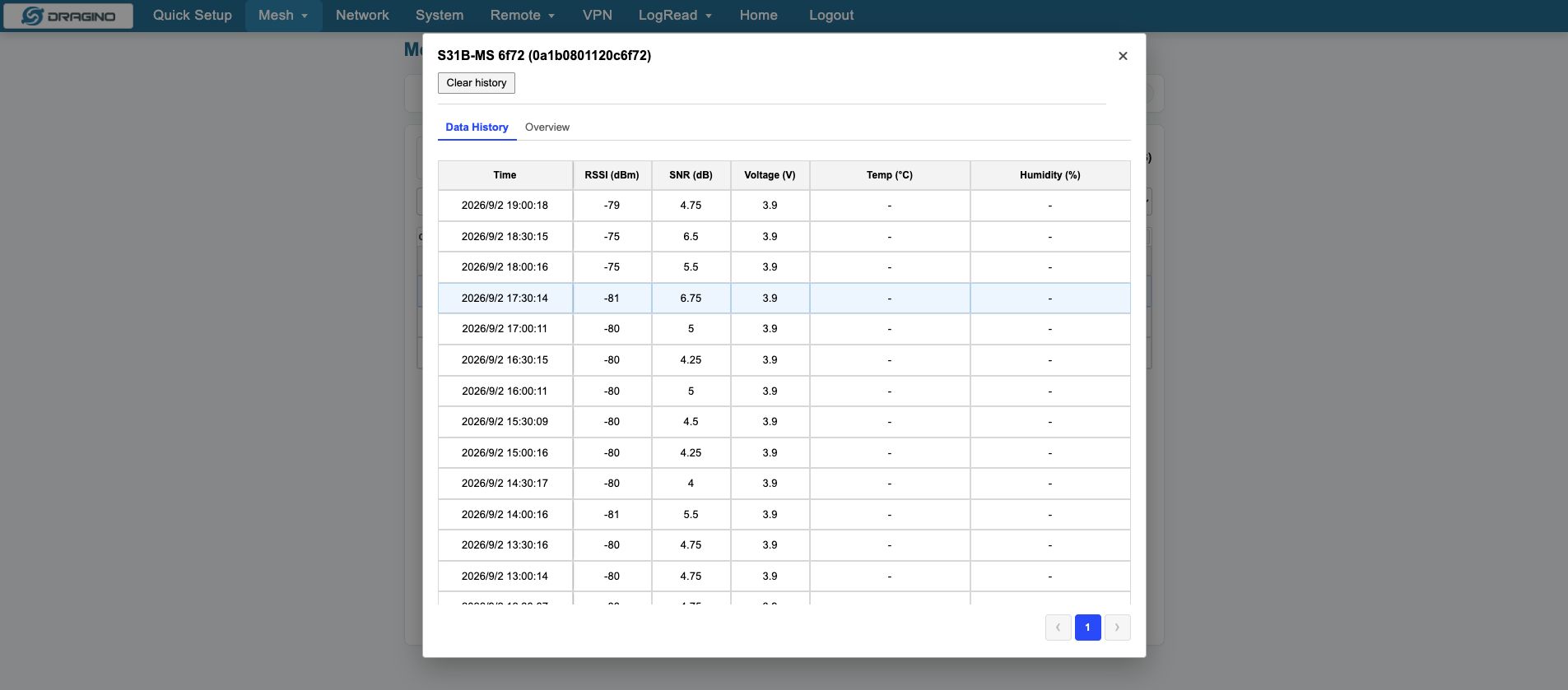
6.3 Node Data History
Open a node to view its Data History. Each record includes time, RSSI, SNR and device-specific business fields.
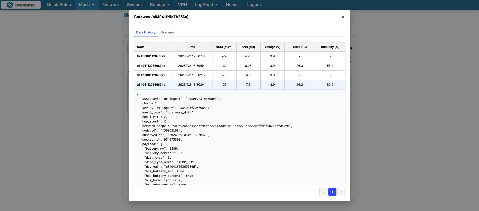
Open a row to view the complete JSON. Common fields include network_scope, node_id, dev_eui_at_ingest, event_type, observed_at, packet_id, rx_rssi, rx_snr, payload and values.
6.4 Node Overview
Node Overview shows Received, Last 1h, Last 24h, Average interval, Longest gap, daily packet count and RSSI/SNR trends. Evaluate trends together with the expected reporting period.
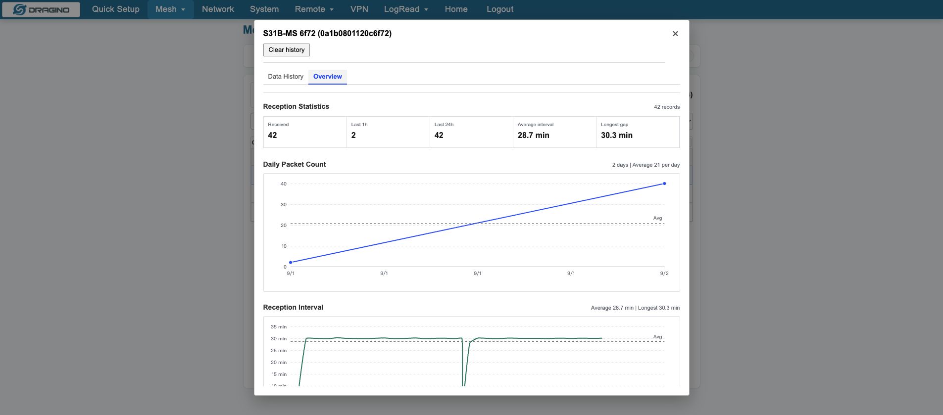
Clear history and Ignore affect stored history. Save required records first.
6.5 MQTT Business Data
Mesh business data → Outbox → MQTT Forwarder → Broker
Use the basic page for Broker, port, credentials and Topic Template.
Use Advanced configuration for Client ID, Protocol, QoS, Keepalive, Poll Interval, Batch Limit and TLS. Client Cert and Client Key must be paired.
Common Topic variables are {HOSTNAME}, {GATEWAY_DEV_EUI}, {BUSINESS_DEV_EUI}, {EVENT_TYPE}, {PACKET_ID} and {OUTBOX_ID}.
7. Remote and VPN Services
Network pages are already covered in Chapter 5 and are not repeated here.
7.1 Remote
7.1.1 Dragino Remote Manager
Use Dragino Remote Manager for continuous remote gateway management. Complete the external network, DNS and time synchronization first, then install the agent, register the gateway and confirm the connection state.
the users can refer to this link to configure them: Dragino Remote Manager
7.1.2 Remote.it
Open Remote → Remote.it to configure remote access through Remote.it. Install the service, enter the Bulk ID Code or Licence Key, save and register. Use Remove when the service is no longer required.
7.1.3 Auto Provision
Auto Provision requests configuration from a provisioning server; it is not continuous remote control. Confirm the Provision server, request an update, and refresh the page to check the version and log.
7.2 VPN
7.2.1 OpenVPN
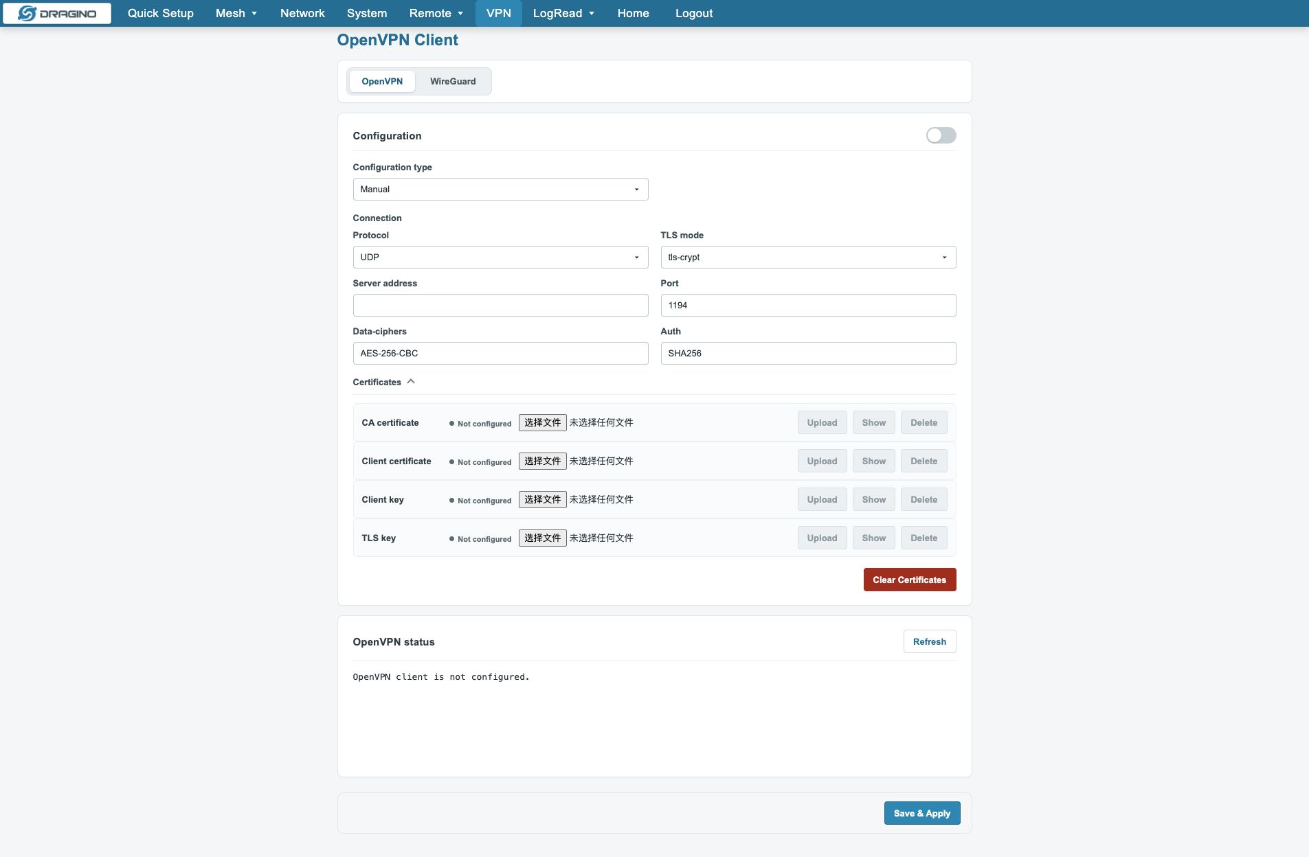
OpenVPN supports manual parameters and certificate/configuration import. After saving, check the interface, connection state, routes and system log.
7.2.2 WireGuard
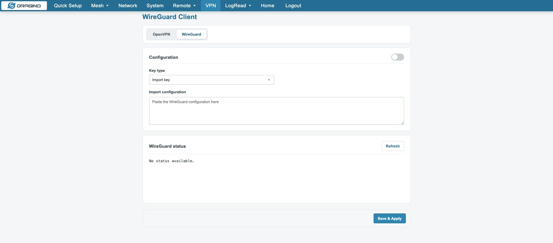
WireGuard can generate a local default key or import an existing configuration. Enter the server address, Allowed IPs, local address, public key and Keep Alive, then save and refresh the status.
Verify VPN in this order:
Configuration saved → materials stored → interface created → tunnel established → routes correct → Mesh/MQTT reachable
8. System Maintenance, Upgrade and Logs
8.1 System Overview
Check model, Host Name, Firmware, Uptime, network and Mesh service status first. A stopped Forwarder can be normal when MQTT is disabled.
8.2 Backup and Restore
Open System → Backup & Restore and use Generate archive. To restore, select the backup and use Upload & restore, then wait for the UI and services to return.
A configuration backup normally includes UCI, account and selected system configuration. Mesh SQLite history, runtime state and MQTT TLS certificates may need separate preservation.
8.3 Reboot and Reset
Reboot normally preserves configuration and temporarily makes the UI unavailable.
Reset restores factory settings and clears related configuration. Back up and prepare a reconnection method first.
8.4 Package Management and Upgrade
Open System → Package Management to check core packages, OTA state and update logs. Back up first, avoid Mesh/MQTT changes during upgrade, then verify firmware, packages and services.
8.5 Service State and Logs
Check Mesh Service State first, then open the Mesh Daemon, Mesh Gateway, MQTT Forwarder or Keep Alive log for the affected link.
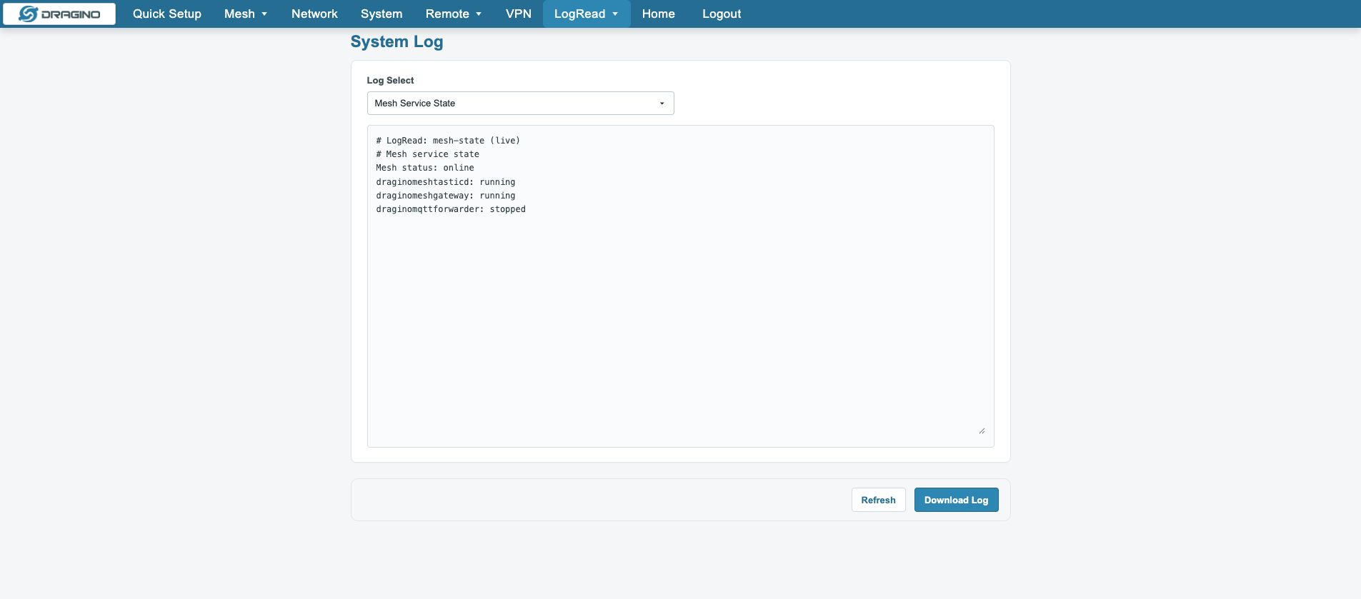
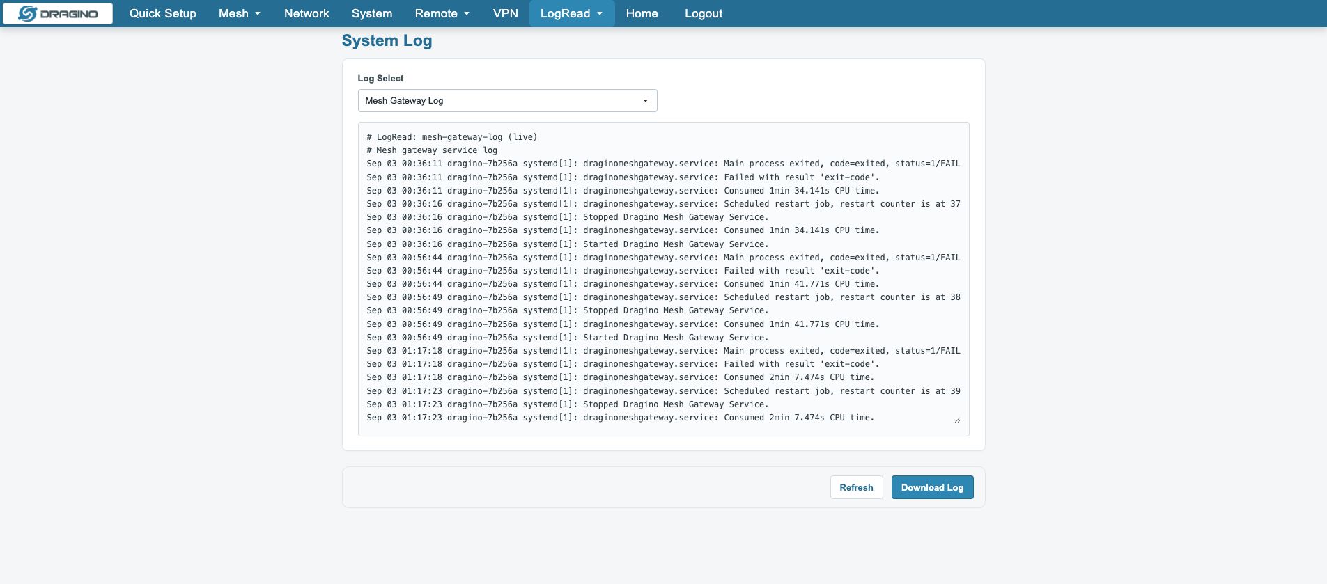
Common services are draginomeshtasticd, draginomeshgateway, draginomqttforwarder and draginoiotkeepalive.
journalctl -u draginomeshtasticd
journalctl -u draginomeshgateway
journalctl -u draginomqttforwarder
journalctl -u draginoiotkeepalive
9. FAQ
9.1 About Network Group and Public Channel
Network Group defines the Mesh network scope and membership. Public Channel is used for public-channel communication. They are different concepts; check the network key, channel settings, node identity and Network Scope separately. Exact fields depend on the device version.
9.2 Sync Sleep/Wake-up for Mesh Network
Coordinate the node sleep/wake behavior with the Mesh Network Wakeup Interval and the node's own reporting period. After a change, wait through several reporting cycles and check Last Seen, reporting intervals and node state.
9.3 How to upgrade IM01v2 to Mesh Gateway mode
Flash the Mesh‑supported firmware for IM01v2. Navigate to System -> General -> Radio Mode and switch the radio mode to Mesh.
9.4 How to Set Up Multiple Mesh Gateways in One Mesh Network
Use matching Mesh network parameters and choose Single Gateway or Multi Gateway according to the deployment design. In Multi Gateway mode, align Network Scope, Network Configuration Sync, RF Region and Network Key, then verify data and MQTT behavior on every gateway.
9.5 How to Use Mesh Network as Part of a LoRaWAN Network
Mesh and LoRaWAN are different radio modes. Mesh business data cannot be treated as LoRaWAN Packet Forwarder data by default. Use an explicitly supported bridge or integration if the product version provides one. Switching Radio Mode interrupts the current Mesh link.
10. Troubleshooting
| Symptom | First checks |
|---|---|
| Web UI unavailable | AP, LAN, address and session |
| Mesh Network page fails | Mesh Daemon, MeshGateway and service logs |
| Node remains waiting | Dev EUI, AppKey, JoinLock, RF Region and Network Key |
| Node active but no business data | Reporting period, payload, filters and logs |
| Mesh Data has data but MQTT has none | Uplink, Broker, Topic, ACL and TLS |
| Multi Gateway does not align | Network Scope, Sync and upstream configuration |
| Services restart repeatedly | Keep Alive, rendering and exit logs |
11. Field Deployment Checklist
- Web UI works and device information is recorded.
- Uplink, address, default route and DNS are verified.
- Mesh Mode, RF Region, Network Mode and Network Key are confirmed.
- Mesh Daemon and MeshGateway are healthy.
- Managed, Observed and Mesh Data states match the plan.
- Data History contains a new business record.
- When enabled, MQTT receives the actual Topic and payload.
- Logs contain no continuing error.
- Backup, business history, certificates and change records are saved.