10xDS18_1xSHT31-LB Firmware Guide
1. Overview
This guide describes the setup and operation of the custom firmware 10xDS18_1xSHT31-LB for the Dragino RS485-LB node. This firmware enables multi-point temperature monitoring by supporting up to 10 DS18B20 sensors and one SHT31 sensor.
2. Hardware Modification and Wiring Reference
2.1 Mandatory Board Modification:
Before connecting any sensors, you must perform the following modification on your RS485-BL motherboard to ensure stable communication with multiple DS18B20 sensors over long cables.
Adding the Pull-up Resistor
- Action: Solder a 1kΩ resistor between the +5V pin and the BOARD_RX pin on the mainboard.
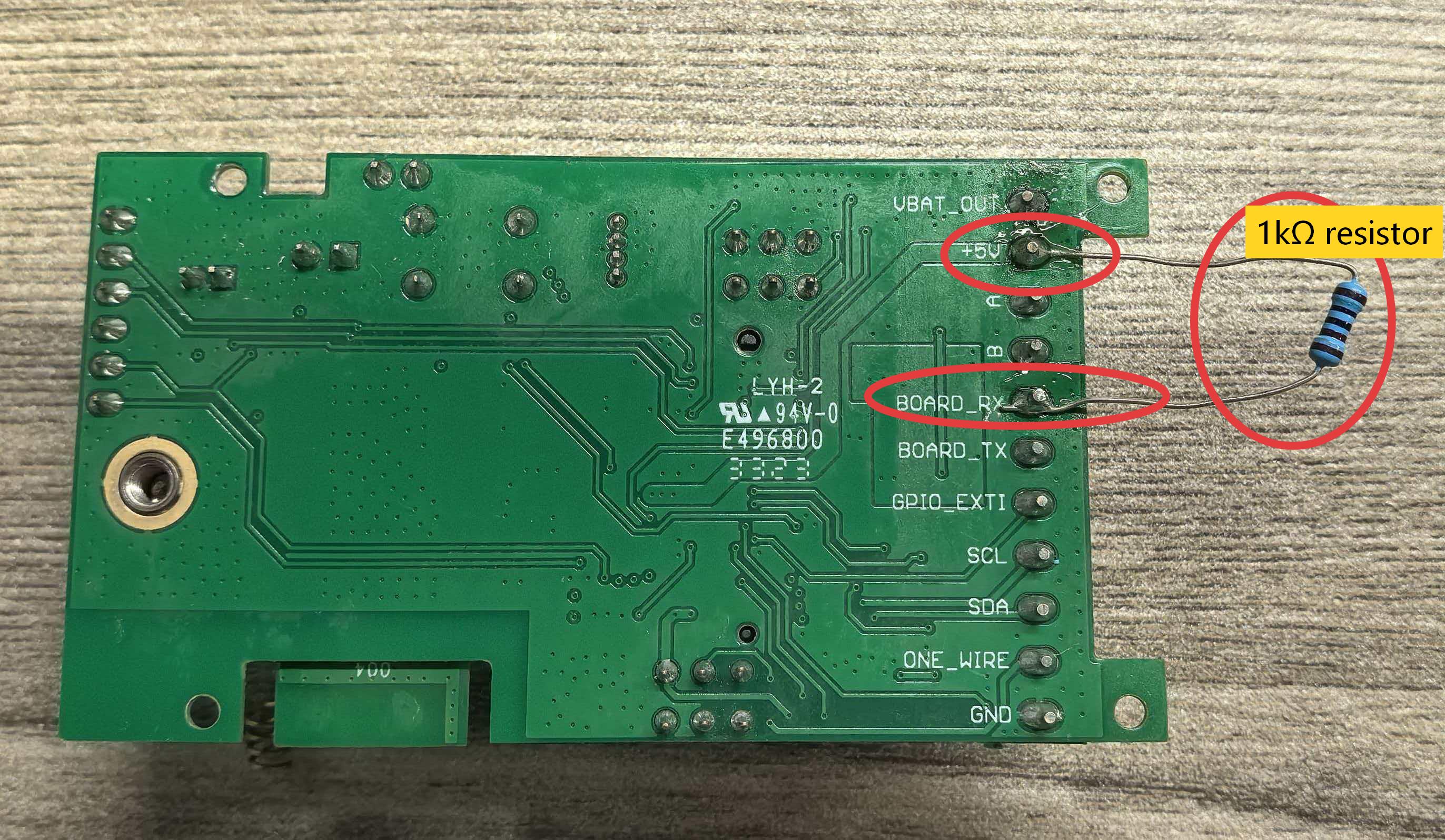
- Purpose: This resistor is critical. It provides the necessary signal strength (“pull-up”) for the 1-Wire communication bus to reliably detect and read from multiple sensors connected to long cables.
- Tested Configuration: With this 1kΩ resistor in place and using the +5V pin for power, this setup has been verified to support up to 10 DS18B20 sensors with a combined cable length of 100 meters.
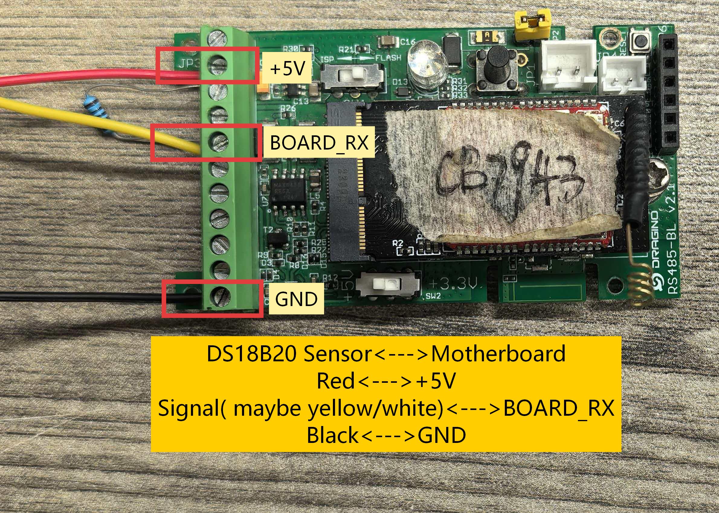
2.2 DS18B20 Wiring:
Diagram for connecting up to 10 sensors in parallel to BOARD_RX, +5V, and GND.
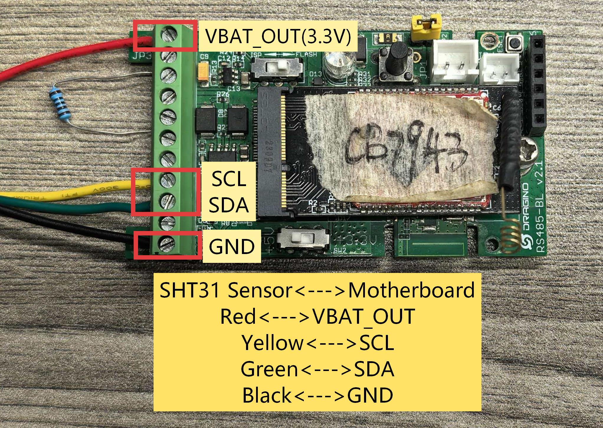
2.3 SHT31 Wiring:
Diagram for I2C connection.
3. Uplink Payload
3.1 Device Status, FPORT=5
Users can use the downlink command(0x26 01) to ask node to send device configure detail, include device configure status. S31x-LB/LS will uplink a payload via FPort=5 to server.
The Payload format is as below.
| Device Status (FPORT=5) | |||||
|---|---|---|---|---|---|
| Size (bytes) | 1 | 2 | 1 | 1 | 2 |
| Value | Sensor Model | Firmware Version | Frequency Band | Sub-band | BAT |
Example parse in TTNv3

Sensor Model: For 10xDS18B20+1xSHT31-LB, this value is 0x30
Firmware Version: 0x0100, Means: v1.0.0 version
Frequency Band:
0x01: EU868
0x02: US915
0x03: IN865
0x04: AU915
0x05: KZ865
0x06: RU864
0x07: AS923
0x08: AS923-1
0x09: AS923-2
0x0a: AS923-3
0x0b: CN470
0x0c: EU433
0x0d: KR920
0x0e: MA869
Sub-Band:
AU915 and US915:value 0x00 ~ 0x08
CN470: value 0x0B ~ 0x0C
Other Bands: Always 0x00
Battery Info:
Check the battery voltage.
Ex1: 0x0B45 = 2885mV
Ex2: 0x0B49 = 2889mV
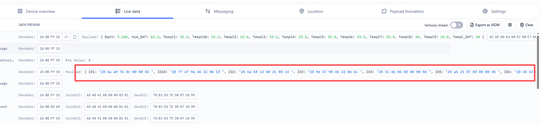
3.2DS18B20 Sensor ID Report, FPORT=5
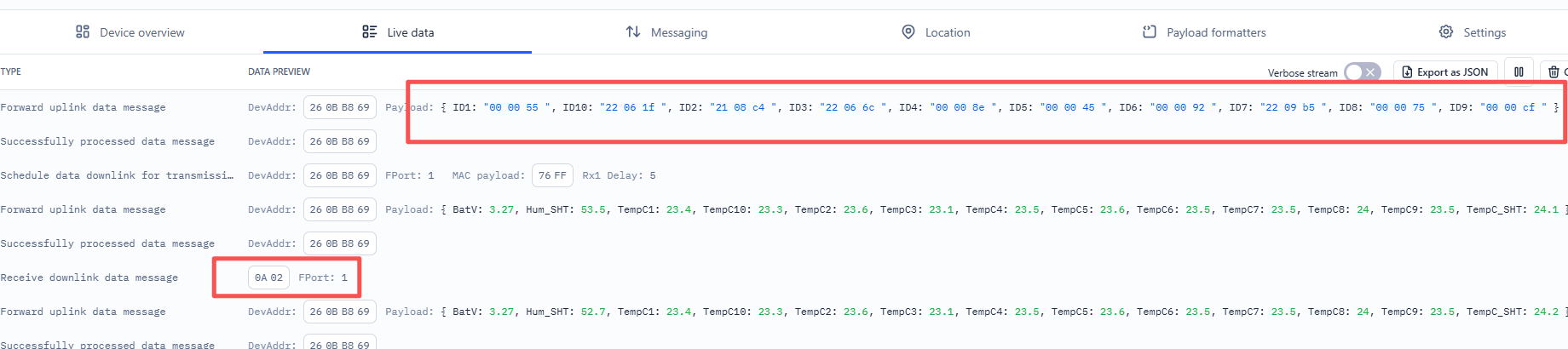
The list of connected DS18B20 sensor IDs is reported via FPort=5 in the following two scenarios:
- Automatically upon each device startup.
- When triggered by the downlink command 0x0A 02.
Payload: A sequence of DS18B20 unique IDs.
ID Format: Controlled by theAT+PIDSETcommand:
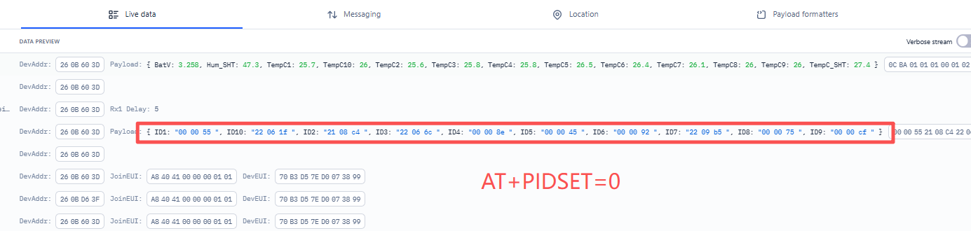
① AT+PIDSET=0(Default): Reports the last 3 bytes of each 8-byte ID (30 bytes max for 10 sensors).
Size(bytes) | 3 | 3 | ... | 3 | 3 |
|---|---|---|---|---|---|
| Value | ID1 | ID2 | ... | ID9 | ID10 |
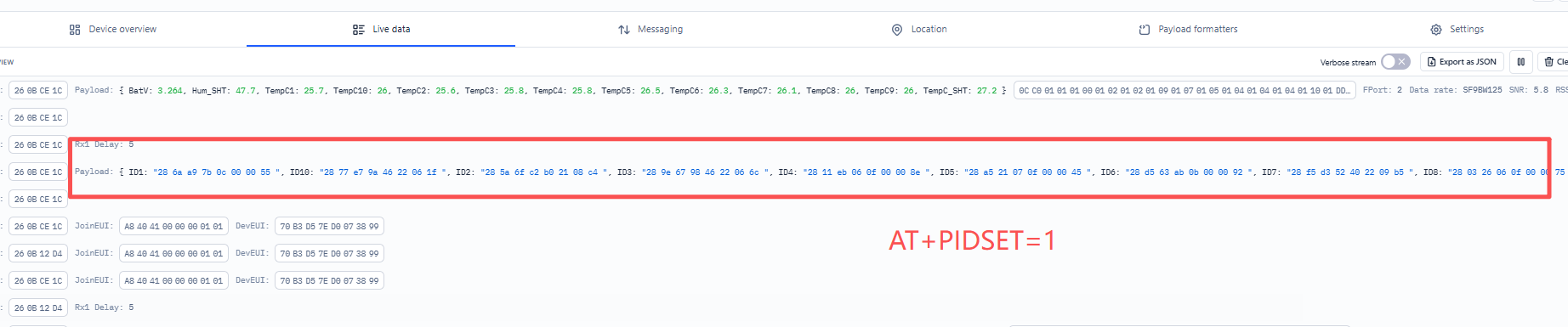
② AT+PIDSET=1: Reports the full 8 bytes of each ID (80 bytes max for 10 sensors).
Size(bytes) | 8 | 8 | ... | 8 | 8 |
|---|---|---|---|---|---|
| Value | ID1 | ID2 | ... | ID9 | ID10 |
3.3 Sensor Data, FPORT=2
Sensor Data is uplink via FPORT=2
Size(bytes) | 2 | 2 | 2 | ... | 2 | 2 | 2 |
|---|---|---|---|---|---|---|---|
| Value | Battery | TempC1 | TempC2 | TempC... | TempC10 | TempC_SHT | Hum_SHT |

Battery
Sensor Battery Level.
Ex1: 0x0B45 = 2885mV
Ex2: 0x0B49 = 2889mV
Temperature (DS18B20 & SHT31)
Fields TempC1 to TempC10 represent the temperature readings from DS18B20 sensors, while TempC_SHT represents the temperature from the SHT31 sensor.
All temperature values are transmitted as a 16-bit signed integer (2 bytes), representing the temperature in °C × 10.
Example:
If payload is: 0105H: (0105 & 8000 == 0), temp = 0105H /10 = 26.1 degree
If payload is: FF3FH : (FF3F & 8000 == 1) , temp = (FF3FH - 65536)/10 = -19.3 degrees.
(FF3F & 8000:Judge whether the highest bit is 1, when the highest bit is 1, it is negative)
Notes:
- If no DS18B20 sensor is detected in a channel, the corresponding field will be filled with the default value 0x7FFF.
- For SHT31, the absence of valid temperature data is also indicated by 0x7FFF.
Humidity (SHT31)
Hum_SHT (SHT31 Humidity) represents the relative humidity, scaled by 10 (%RH × 10).
Decoding Rule: Humidity (%RH) = Value / 10
Example:
0x0197 (407 in decimal): 40.7 %RH
Notes:
For SHT31, the absence of valid humidity data is indicated by 0xFFFF.
4. Special Command
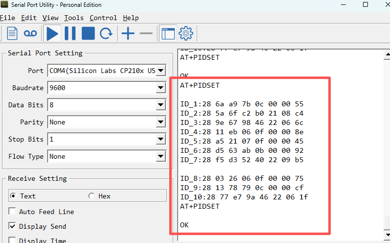
This command configures how DS18B20 sensor IDs are reported or triggers an immediate ID scan.
4.1 AT+PIDSET
Action: Immediately scans for and reports all connected DS18B20 IDs.
Downlink Equivalent: 0x0A 02
Example:

4.2 AT+PIDSET=0 (Default Mode)
Action: Sets the system to report only the last 3 bytes of each DS18B20's 8-byte unique ID.
Downlink Equivalent: 0x0A 00
Example:
4.3 AT+PIDSET=1
Action: Sets the system to report the full 8 bytes of each DS18B20's unique ID.
Downlink Equivalent: 0x0A 01
Example:
5. Download & Decoder
5.1 Firmware
Download the latest 10xDS18_1xSHT31-LB firmware from the link below:
Firmware: [Link to be updated]
5.2 Payload Decoder
Use the following decoder to parse the uplink data (FPort 2 & 5) on your LoRaWAN® Network Server (e.g., TTN, ChirpStack):
Decoder: [Link to be updated]