IVS-LN
1. Introduction
1.1 What is LoRaWAN Industrial Vibration Sensor
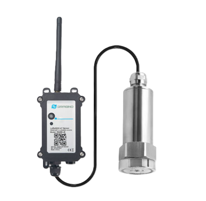
The Dragino IVS-LN is a LoRaWAN Vibration Sensor for Internet of Things solution. It is used to measure the vibration frequency of industrial motors, water pumps, fans, and other rotating equipment, and then upload to IoT server via LoRaWAN wireless protocol.
The industrial vibration sensor used in the IVS-LN is a composite vibration sensor. This sensor uses the standard Modbus-RTU protocol for data output and offers exceptional reliability and long-term stability.
The LoRa wireless technology used in IVS-LN allows device to send data and reach extremely long ranges at low data-rates. It provides ultra-long range spread spectrum communication and high interference immunity whilst minimizing current consumption.
IVS-LN supports Vibration alarm feature, users can set vibration-related alarm parameters to receive instant notifications. IVS-LN supports Datalog feature, it can save the data when there is no LoRaWAN network and uplink when network recover.
IVS-LN supports BLE configure and wireless OTA update which make user easy to use.
IVS-LN is powered by DC Power + 1000mAh BackUp Battery it is designed for long term.
Each IVS-LN is pre-load with a set of unique keys for LoRaWAN registrations, register these keys to local LoRaWAN server and it will auto connect after power on.
1.2 Features
- LoRaWAN 1.0.3 Class A
- Vibration alarm
- Compliant with ISO 20816-1 vibration evaluation guidelines.
- Monitor: RMS Acceleration/RMS Velocity/Vibration Frequency/Vibration Displacement/Temperature
- Bands: CN470/EU433/KR920/US915/EU868/AS923/AU915/IN865/RU864/MA869
- Support Bluetooth v5.1 and LoRaWAN remote configure
- Support wireless OTA update firmware
- Uplink on periodically
- Downlink to change configure
1.3 Specification
Common DC Characteristics:
- Operating Temperature: -40 ~ 85°C
Vibration Measure Parameters:
- Frequency: 10
1600Hz or 105000Hz - RMS Velocity: 0~ 50 mm/s, Accuracy:<1%
- Vibration Displacement: 0-5000 um (Peak-to-Peak)
- RMS Acceleration: 16g, Accuracy : <1%
- Surface Temperature: -40 ~ 80°C
Power Supply (IVS-LN):
- DC Power + 1000mAh Backup Battery (IVS-LN)
LoRa Spec:
- Frequency Range, Band 1 (HF): 862 ~ 1020 Mhz
- Max +22 dBm constant RF output vs.
- RX sensitivity: down to -139 dBm.
- Excellent blocking immunity
Battery:
- 1000mAh BackUp Battery
- Capacity: 1000mAh
- Self-Discharge: <1% / Year @ 25°C
- Max continuously current: 130mA
- Max boost current: 2A, 1 second
Power Consumption
- Sleep Mode: 5uA @ 3.3v
- LoRa Transmit Mode: 125mA @ 20dBm, 82mA @ 14dBm
1.4 Sleep mode and working mode
Deep Sleep Mode: Sensor doesn't have any LoRaWAN activate. This mode is used for storage and shipping to save battery life.
Working Mode: In this mode, Sensor will work as LoRaWAN Sensor to Join LoRaWAN network and send out sensor data to server. Between each sampling/tx/rx periodically, sensor will be in IDLE mode), in IDLE mode, sensor has the same power consumption as Deep Sleep mode.
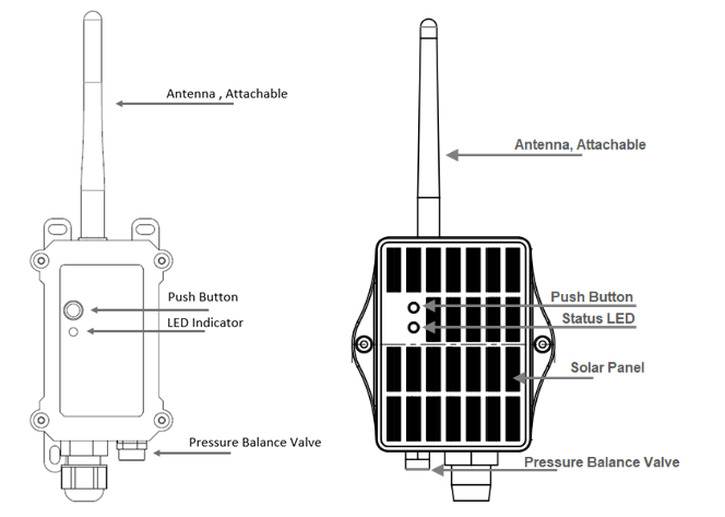
1.5 Button & LEDs
| Behavior on ACT | Function | Action |
|---|---|---|
| Send an uplink | If sensor is already Joined to LoRaWAN network, sensor will send an uplink packet, blue led will blink once. Meanwhile, BLE module will be active and user can connect via BLE to configure device. | |
| Active Device | Green led will fast blink 5 times, device will enter OTA mode for 3 seconds. And then start to JOIN LoRaWAN network. Green led will solidly turn on for 5 seconds after joining the network. Once sensor is active, BLE module will be active and user can connect via BLE to configure device, no matter if device join or not join LoRaWAN network. | |
| Deactivate Device | Red led will solid on for 5 seconds. Means device is in Deep Sleep Mode. |
1.6 BLE connection
IVS-LN support BLE remote configure.
BLE can be used to configure the parameter of sensor or see the console output from sensor. BLE will be only activate on below case:
- Press button to send an uplink
- Press button to active device.
- Device Power on or reset.
If there is no activity connection on BLE in 60 seconds, sensor will shut down BLE module to enter low power mode.
1.7 Pin Definitions
-45c99dbde93a3e8173c3325199aec460.jpeg)
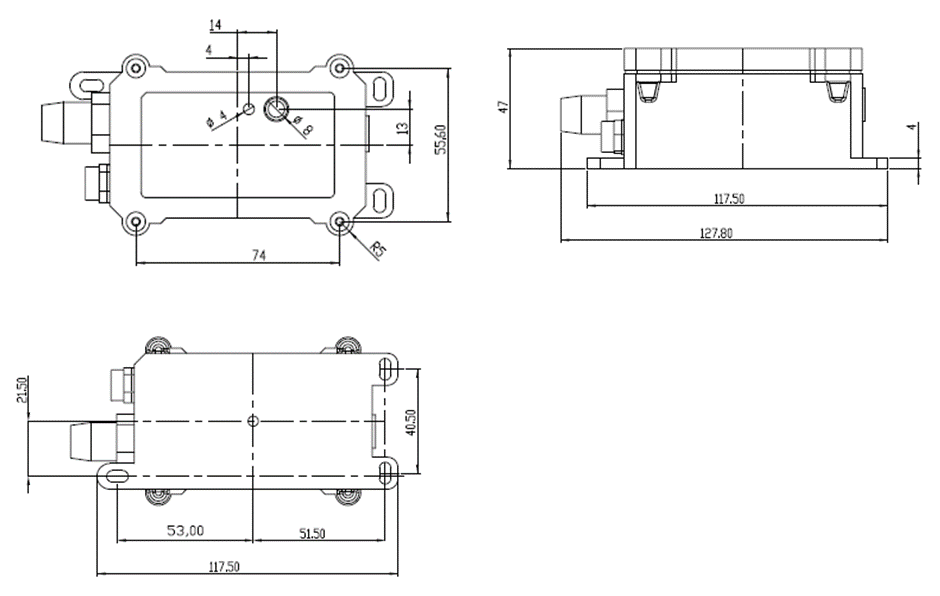
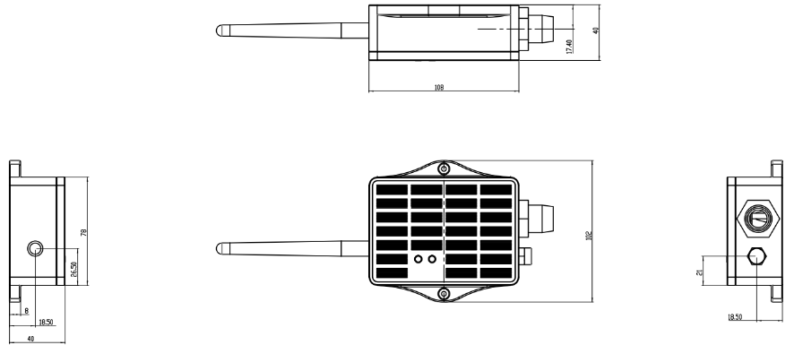
1.8 Mechanical
1.8.1 for LB version
1.8.2 for LS version
1.9 ISO standard Reference
IVS-LN is compliant with ISO 20816-1 vibration evaluation guidelines. ISO 20816-1 provides general guidelines for measuring and evaluating machine vibration and can be used as a reference for equipment condition monitoring and fault diagnosis.
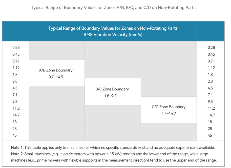
Additional Notes
Since the above data is taken from a basic document providing general guidelines for the measurement and evaluation of mechanical vibration in machines, no specific evaluation criteria for machines are defined. For machine types without specific international standards, evaluation criteria are usually based on successful operating experience with similarly designed machines and shall be subject to agreement between the machine supplier and the customer. Factors to be considered include measurement location and direction, frequency range, support flexibility, and operating conditions. In the absence of adequate experience or international standards, the table above gives typical ranges for the boundaries of zones A/B, B/C and C/D on non-rotating parts. For specific equipment types, priority should be given to the corresponding clauses of ISO 20816 and equivalent national standards such as the GB/T 41850 series.
2. Configure IVS-LN to connect to LoRaWAN network
2.1 How it works
The IVS-LN is configured as LoRaWAN OTAA Class A mode by default. It has OTAA keys to join LoRaWAN network. To connect a local LoRaWAN network, you need to input the OTAA keys in the LoRaWAN IoT server and press the button to activate the IVS-LN. It will automatically join the network via OTAA and start to send the sensor value. The default uplink interval is 20 minutes.
2.2 Quick guide to connect to LoRaWAN server (OTAA)
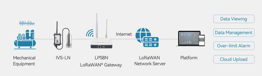
Following is an example for how to join the TTN v3 LoRaWAN Network. Below is the network structure; we use the LPS8v2 as a LoRaWAN gateway in this example.
The LPS8V2 is already set to connected to TTN network, so what we need to now is configure the TTN server.
Step 1: Create a device in TTN with the OTAA keys from IVS-LN.
Each IVS-LN is shipped with a sticker with the default device EUI as below:
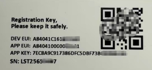
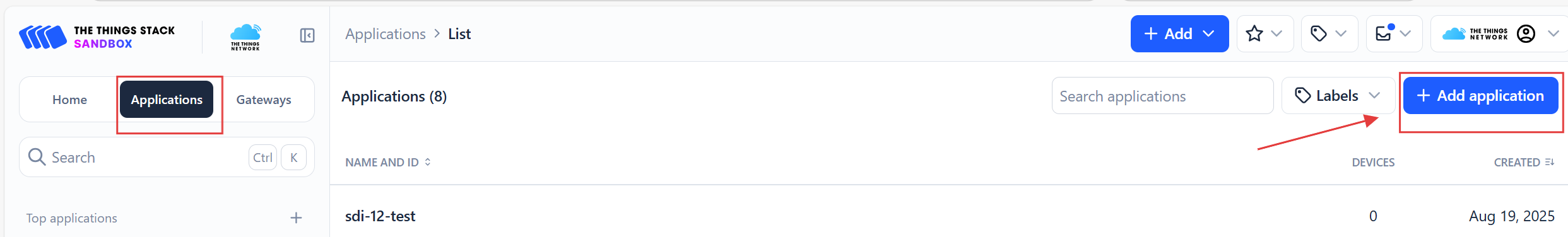
You can enter this key in the LoRaWAN Server portal. Below is TTN screen shot:
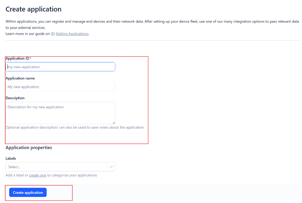
Create the application.
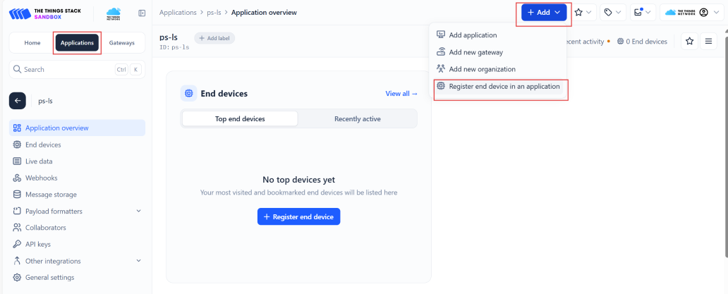
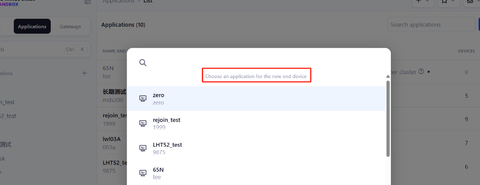
Add devices to the created Application.
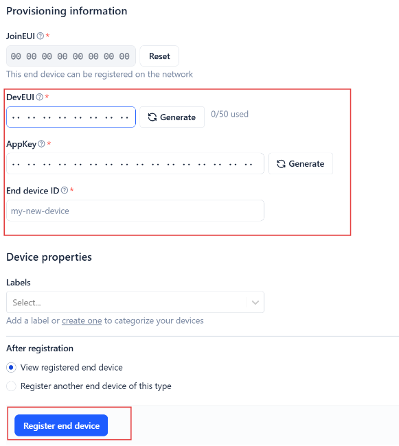
Enter end device specifics manually.
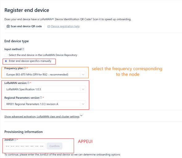
Add DevEUI and AppKey. Customize a platform ID for the device.
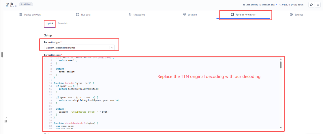
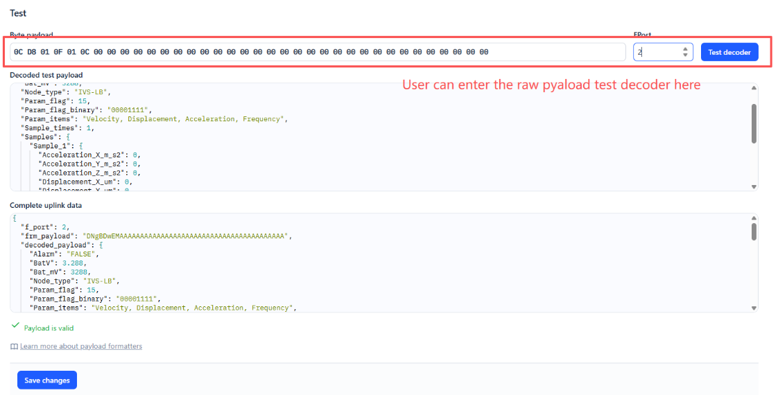
Step 2: Add decoder.
In TTN, user can add a custom payload so it shows friendly reading.
Click this link to get the decoder: https://github.com/dragino/dragino-end-node-decoder/tree/main/
Below is TTN screen shot:
Step 3: Activate on IVS-LN
Press the button for 5 seconds to activate the IVS-LN.
Green led will fast blink 5 times, device will enter OTA mode for 3 seconds. And then start to JOIN LoRaWAN network. Green led will solidly turn on for 5 seconds after joined in network.
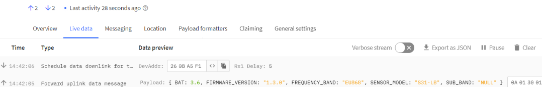
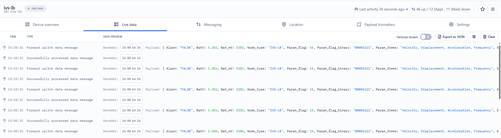
After join success, it will start to upload messages to TTN and you can see the messages in the panel.
2.3 Uplink Payload
2.3.1 Device Status, FPORT=5
Users can use the downlink command(0x26 01) to ask IVS-LN to send device configure detail, include device configure status. IVS-LN will uplink a payload via FPort=5 to server.
The Payload format is as below.
| Device Status (FPORT=5) | |||||
| Size (bytes) | 1 | 2 | 1 | 1 | 2 |
| Value | Sensor Model | Firmware Version | Frequency Band | Sub-band | BAT |
Example parse in TTNv3
Sensor Model: For IVS-LN, this value is 0x51
Firmware Version: 0x0100, Means: v1.0.0 version
Frequency Band:
0x01: EU868
0x02: US915
0x03: IN865
0x04: AU915
0x05: KZ865
0x06: RU864
0x07: AS923
0x08: AS923-1
0x09: AS923-2
0x0a: AS923-3
0x0b: CN470
0x0c: EU433
0x0d: KR920
0x0e: MA869
Sub-Band:
AU915 and US915:value 0x00 ~ 0x08
CN470: value 0x0B ~ 0x0C
Other Bands: Always 0x00
Battery Info:
Check the battery voltage.
Ex1: 0x0B45 = 2885mV
Ex2: 0x0B49 = 2889mV
2.3.2 Sensor Data. FPORT=2
2.3.2.1 Single-Package Mode(AT+DATAUP=0)
Sensor Data is uplink via FPORT=2
The following explanation uses AT+VIBE=15,1,2000as an example.
Note:
1. The device calculates the number of bytes in the uplink payload based on the customer-configured sampling parameters and sampling rate, and determines the minimum DR suitable for decoding.
2. If the number of bytes in the payload exceeds the maximum size for a single packet, the excess groups are removed (the groups sampled first are removed; the excess portion is treated as a single group for evaluation; the parameters within a single group are not split), ensuring that the entire payload can be sent in a single packet. This feature is primarily intended for cases where ADR=1; note that if ADR is configured as 0, packet splitting mode must be used.
| Size(bytes) | 2 | 1 | 1 | 2 | 6 | 6 | 6 | 12 |
|---|---|---|---|---|---|---|---|---|
| Value | Battery | Sampling Times | Sampling Parameters | Temperature | X,Y,Z Vibration Velocity | X,Y,Z Vibration Displacement | X,Y,Z Acceleration | X,Y,Z Frequency |
Battery
Sensor Battery Level.
Ex1: 0x0B45 = 2885mV
Ex2: 0x0B49 = 2889mV
Number of samples:
Example:
If payload is: 01H = 1 tims
Sampling parameters
Example:
If payload is: 0FH = 15 --> //Specify all sampling parameters: vibration velocity, vibration displacement, vibration acceleration, and vibration frequency.
Temperature
Example:
If payload is: 010BH: (010B & 8000 == 0), temp = 010BH /10 = 26.7 degree
If payload is: FF3FH : (FF3F & 8000 == 1) , temp = (FF3FH - 65536)/10 = -19.3 degrees.
(FF3F & 8000:Judge whether the highest bit is 1, when the highest bit is 1, it is negative)
X,Y,Z Vibration Velocity
Example:
If payload is: 0x001000000017H
The vibration velocity values for X, Y, and Z are as follows:
Vibration velocity values on the X-axis: 0x0010 = 16 / 10 =1.6 mm/s Vibration velocity values on the Y-axis: 0x0000 = 0 / 10 = 0 mm/s Vibration velocity values on the Z-axis: 0x0017 = 23 / 10 = 2.3 mm/s
X,Y,Z Vibration Displacement
Example:
If payload is:0x04E30000071DH
The vibration displacement values for the X, Y, and Z axes are as follows: X-axis vibration displacement: 0x04E3 = 1251 / 10 =125.1 µm Y-axis vibration displacement: 0x0000 = 0 / 10 = 0 µm Z-axis vibration displacement: 0x071D = 1821 / 10 =182.1 µm
X,Y,Z Acceleration
Example:
If payload is:0x000100020001H
The vibration acceleration values for the X, Y, and Z axes are as follows: Vibration acceleration value for the X axis: 0x0001 = 1 / 10 = 0.1 m/s² Vibration acceleration value for the Y axis: 0x0002 = 2 / 10 = 0.2 m/s² Vibration acceleration value for the Z axis: 0x0001 = 1 / 10 = 0.1 m/s²
X,Y,Z Frequency
Example:
If payload is:0x4111BAAB40B6880140F7D1DC
The vibration frequencies for the X, Y, and Z axes are as follows: X-axis vibration frequency: 0x4111BAAB = 9.108073234558105 Hz(float Type) Y-axis vibration frequency: 0x40B68801 = 5.704102039337158 Hz(float Type) Z-axis vibration frequency: 0x40F7D1DC = 7.744367599487305 Hz(float Type)
Note: In the uplink data packet, the vibration frequency payload must be converted directly from HEX format to a float type. Recommended tool: HEX TO FLOA
2.3.2.2 Subcontracting Mode (AT+DATAUP=1)
1. There are currently no decoders that support the sub-packet model.
2.The maximum number of bytes is calculated based on the maximum supported bytes for the lowest modulation order in each frequency band. As follows:
- For the AU915/AS923 bands, if Uplink Dwell Time = 0, the maximum number of bytes per uplink is 51 (i.e., 51 = 45 maximum payload bytes)
- For the AU915/AS923 bands, if Uplink Dwell Time = 1, each uplink transmission is limited to a maximum of 11 bytes (i.e., 11 = 5 maximum valid data bytes).
- For the US915 band, each uplink transmission is limited to a maximum of 11 bytes (i.e., 11 = 5 maximum valid data bytes).
- For all other bands: a maximum of 51 bytes per uplink (i.e., 51 = 45 maximum valid data units).
3. When AT+ADR=0, the maximum number of bytes in the payload is determined by the DR value.
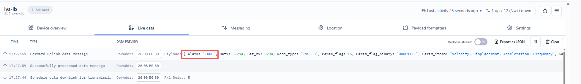
2.3.3 ALARM Mode
Sensor Data is uplink via FPORT=10
The following explanation uses AT+VIBE=15,1,2000, AT+ALARM=1,15,0,5,0,200,0,5,0,10as an example.
Note: The alarm mode is set to trigger once per minute. The alarm will stop when the monitored value falls within the configured threshold or when a manual alarm cooldown period is set.
| Size(bytes) | 2 | 1 | 1 | 2 | 6 | 6 | 6 | 12 |
|---|---|---|---|---|---|---|---|---|
| Value | Battery | Sampling Times | Sampling Parameters | Temperature | X,Y,Z Vibration Velocity | X,Y,Z Vibration Displacement | X,Y,Z Acceleration | X,Y,Z Frequency |
Battery
Sensor Battery Level.
Ex1: 0x0B45 = 2885mV
Ex2: 0x0B49 = 2889mV
Number of samples:
Example:
If payload is: 01H = 1 tims
Sampling parameters
Example:
If payload is: 0FH = 15 --> //Specify all sampling parameters: vibration velocity, vibration displacement, vibration acceleration, and vibration frequency.
Temperature
Example:
If payload is: 010BH: (010B & 8000 == 0), temp = 010BH /10 = 26.7 degree
If payload is: FF3FH : (FF3F & 8000 == 1) , temp = (FF3FH - 65536)/10 = -19.3 degrees.
(FF3F & 8000:Judge whether the highest bit is 1, when the highest bit is 1, it is negative)
X,Y,Z Vibration Velocity
Example:
If payload is: 0x0130013A01F4H
The vibration velocity values for X, Y, and Z are as follows:
Vibration velocity values on the X-axis: 0x0130 = 304 / 10 =30.4 mm/s Vibration velocity values on the Y-axis: 0x013A = 314 / 10 = 31.4 mm/s Vibration velocity values on the Z-axis: 0x01F4 = 500 / 10 = 50 mm/s
X,Y,Z Vibration Displacement
Example:
If payload is:0x1B112DA37EF5H
The vibration displacement values for the X, Y, and Z axes are as follows: X-axis vibration displacement: 0x1B11 = 6929 / 10 =692.9 µm Y-axis vibration displacement: 0x2DA3 = 11683 / 10 =1168.3 µm Z-axis vibration displacement: 0x7EF5 = 32501 / 10 =3250.1 µm
X,Y,Z Acceleration
Example:
If payload is:0x0047006B0076H
The vibration acceleration values for the X, Y, and Z axes are as follows: Vibration acceleration value for the X axis: 0x0047 = 71 / 10 = 7.1 m/s² Vibration acceleration value for the Y axis: 0x006B = 107 / 10 = 10.7 m/s² Vibration acceleration value for the Z axis: 0x0076 = 118 / 10 = 11.8 m/s²
X,Y,Z Frequency
Example:
If payload is:0x42922CC84225F25A41C3A0EE
The vibration frequencies for the X, Y, and Z axes are as follows: X-axis vibration frequency: 0x42922CC8 = 73.08746337890625 Hz(float Type) Y-axis vibration frequency: 0x4225F25A = 41.486671447753906 Hz(float Type) Z-axis vibration frequency: 0x41C3A0EE = 24.45357894897461 Hz(float Type)
Note:In the uplink data packet, the vibration frequency payload must be converted directly from HEX format to a float type. Recommended tool: HEX TO FLOA
2.4 Payload Decoder file
In TTN, use can add a custom payload so it shows friendly reading
In the page Applications --> Payload Formats --> Custom --> decoder to add the decoder from:
https://github.com/dragino/dragino-end-node-decoder/tree/main/IVS-LB
2.5 Datalog Feature
Datalog Feature is to ensure IoT Server can get all sampling data from Sensor even if the LoRaWAN network is down. For each sampling, IVS-LN will store the reading for future retrieving purposes.
2.5.1 How datalog works
IVS-LN will wait for ACK for every uplink, when there is no LoRaWAN network,IVS-LN will mark these records with non-ack messages and store the sensor data, and it will send all messages (10s interval) after the network recovery.
-
a) IVS-LN will do an ACK check for data records sending to make sure every data arrive server.
-
b) IVS-LN will send data in CONFIRMED Mode, but IVS-LN won't re-transmit the packet if it doesn't get ACK, it will just mark it as a NONE-ACK message. In a future uplink if IVS-LN gets a ACK, IVS-LN will consider there is a network connection and resend all NONE-ACK messages.
2.5.2 Enable Datalog
User need to make sure below two settings are enable to use datalog;
- SYNCMOD=1(Default) to enable sync time via LoRaWAN MAC command, click here (AT+SYNCMOD) for detailed instructions.
- PNACKMD=1** **to enable datalog feature, click here (AT+PNACKMD) for detailed instructions.
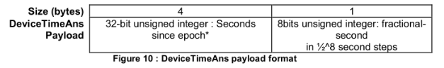
Once IVS-LN Joined LoRaWAN network, it will send the MAC command (DeviceTimeReq) and the server will reply with (DeviceTimeAns) to send the current time to IVS-LN. If IVS-LN fails to get the time from the server, IVS-LN will use the internal time and wait for next time request (AT+SYNCTDC to set the time request period, default is 10 days).
Note: LoRaWAN Server need to support LoRaWAN v1.0.3(MAC v1.0.3) or higher to support this MAC command feature, Chirpstack,TTN V3 v3 and loriot support but TTN V3 v2 doesn't support. If server doesn't support this command, it will through away uplink packet with this command, so user will lose the packet with time request for TTN V3 v2 if SYNCMOD=1.
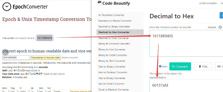
2.5.3 Unix TimeStamp
IVS-LN uses Unix TimeStamp format based on
User can get this time from link: https://www.epochconverter.com/ :
Below is the converter example
2.5.4 Poll sensor value
User can poll sensor value based on timestamps from the server. Below is the downlink command.
| 1byte | 4bytes | 4bytes | 1byte |
|---|---|---|---|
| 31 | Timestamp start | Timestamp end | Uplink Interval(range 5~255s) |
Timestamp start and Timestamp end use Unix TimeStamp format as mentioned above. Devices will reply with all data log during this time period, use the uplink interval.
For example, downlink command 31 6A3DF364 6A3DF4CC 05
Is to check 2026/6/26 03:35:00 to 2026/6/26 03:41:00's data
Uplink Internal =5s, means RS485-LB will send one packet every 5s.
2.5.5 Datalog Uplink payload (FPORT=3)
The Datalog uplinks will use below payload format.
Retrieval data payload:
| Size(bytes) | 4 | 1 | Length depends on the return from the commands |
|---|---|---|---|
| Value | Unix Time Stamp | Payload Length | Data returned by the sensor |
Example:
If IVS-LN has below data inside Flash:
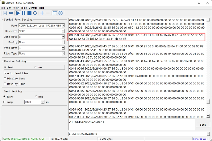
If user sends below downlink command: 316A3DF3646A3DF4CC05
Where : Start time: 646D84E1 = time 26/6/26 03:35:00
Stop time: 646D856C= time 26/6/26 03:41:00
IVS-LN will uplink this payload.
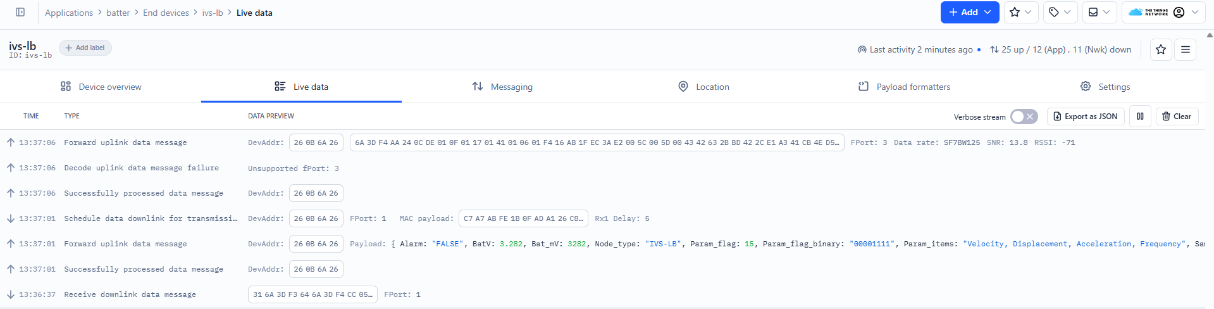
6A 3D F4 AA 24 0C DE 01 0F 01 17 01 41 01 06 01 F4 16 AB 1F EC 3A E2 00 5C 00 5D 00 43 42 63 2B BD 42 2C E1 A3 41 CB 4E D5
Unix time is 0x6A3DF4AA = 1782445226s = 26/6/26 03:35:00
Payload Length = 0x24 = 36 Total Valid Bytes
BatV: 0x0CDE = 3294mv/1000 = 3.294V
Number of samples: 0x01 = 1 times
Sampling parameters: 0x0F = 15 (vibration velocity, vibration displacement, vibration acceleration, vibration frequency)
Temp = 0x0117/10=27.9°C
Vibration velocity along the x-axis = 0x01 41 = 321 / 10 = 32.1 mm/s
Vibration velocity along the y-axis = 0x01 06 = 262 / 10 =26.2 mm/s
Vibration velocity along the z-axis = 0x01 F4 = 500 / 10 = 50.0 mm/s
Vibration displacement along the x-axis = 0x16 AB = 5803 / 10 = 580.3µm
Vibration displacement along the y-axis = 0x1F EC = 8172 / 10 = 817.2µm
Vibration displacement along the z-axis = 0x3A E2 = 15074 / 10 = 1507.4µm
Vibration acceleration along the x-axis = 0x00 5C = 92 / 10 = 9.2 m/s²
Vibration acceleration along the y-axis = 0x00 5D = 93 / 10 = 9.3 m/s²
Vibration acceleration along the z-axis = 0x00 43 = 67 / 10 = 6.7 m/s²
Vibration frequency along the x-axis = 0x42 63 2B BD = 56.7927131652832 Hz(float Type)
Vibration frequency along the y-axis = 0x42 2C E1 A3 = 43.2203483581543 Hz(float Type)
Vibration frequency along the z-axis = 0x41 CB 4E D5 = 25.41349220275879 Hz(float Type)
Note:In the uplink data packet, the vibration frequency payload must be converted directly from HEX format to a float type. Recommended tool: HEX TO FLOAT
2.6 Frequency Plans
The IVS-LN uses OTAA mode and below frequency plans by default. Each frequency band use different firmware, user update the firmware to the corresponding band for their country. See:Frequency Plans
2.7 Firmware Change Log
Firmware download link:https://www.dropbox.com/sh/fis3g6nmhv0eokg/AAC6BcCZaX4BdqZkduUvZ3jIa?dl=0
3. Configure IVS-LN
3.1 Configure Methods
IVS-LN supports below configure method:
- AT Command via Bluetooth Connection (Recommended): BLE Configure Instruction.
- AT Command via UART Connection : See UART Connection.
- LoRaWAN Downlink. Instruction for different platforms: See IoT LoRaWAN Server section.
3.2 General Commands
These commands are to configure:
- General system settings like: uplink interval.
- LoRaWAN protocol & radio related command.
They are same for all Dragino Devices which support DLWS-005 LoRaWAN Stack. These commands can be found on the wiki: AT Commands Downlink
3.3 Commands special design for IVS-LN
These commands only valid for IVS-LN, as below:
3.3.1 Set Transmit Interval Time
Feature: Change LoRaWAN End Node Transmit Interval.
AT Command: AT+TDC
| Command Example | Function | Response |
|---|---|---|
| AT+TDC=? | Show current transmit Interval | 30000 OK the interval is 30000ms = 30s |
| AT+TDC=60000 | Set Transmit Interval | OK Set transmit interval to 60000ms = 60 seconds |
Downlink Command: 0x01
Format: Command Code (0x01) followed by 3 bytes time value.
If the downlink payload=0100003C, it means set the END Node's Transmit Interval to 0x00003C=60(S), while type code is 01.
- Example 1: Downlink Payload: 0100001E // Set Transmit Interval (TDC) = 30 seconds
- Example 2: Downlink Payload: 0100003C // Set Transmit Interval (TDC) = 60 seconds
3.3.2 Get Device Status
Send a LoRaWAN downlink to ask device send Alarm settings.
Downlink Payload: 0x26 01
Sensor will upload Device Status via FPORT=5. See payload section for detail.
3.3.3 Set Sampling Items
Function: Configure the vibration sensor's data points, sampling rate, and sampling interval.
- AT Command:
AT+VIBE=<enable_bits>,<MC>,<ST>
Parameter Description:
<enable_bits>: Data Collection Item Mask.(1 = velocity, 2 = displacement, 4 = Acceleration, 8 = frequency)
<MC>: Number of samples, range: 155
<ST>: Sampling interval, range: 100ms0,000ms, unit ms
Note: The enable_bits parameter depends on the sum of the sensor parameter codes to be sampled. For example, if you need to sample both vibration velocity and vibration displacement, set it to 3-the sum of the vibration velocity code (1) and the vibration displacement code (2).
Example:
AT+VIBE=3,3,1000 --> Collect vibration velocity and vibration displacement, taking three samples at 1,000-millisecond intervals.
AT+VIBE=7,3,1000 --> Record vibration velocity, vibration displacement, and vibration acceleration, taking three samples at 1,000-millisecond intervals.
AT+VIBE=15,3,1000 --> Collect all vibration data points, taking 3 samples at 1000-millisecond intervals.
- Downlink Payload:
0xB0 03 03 03 E8 --> Same as AT+VIBE=3,3,1000
0xB0 07 03 03 E8 --> Same as AT+VIBE=7,3,1000
0xB0 0F 03 03 E8 --> Same as AT+VIBE=15,3,1000
3.3.4 Set Alarm Threshold
Feature: Configure the vibration alarm switch and set the upper and lower thresholds for monitoring vibration velocity, vibration displacement, vibration acceleration, and vibration frequency.
- AT Command:
AT+ALARM=<enable>,<mask>,<thresholds...>
Parameter Description:
<enable>: Configure the alarm function: Enable or disable. (1: Enable; 0: Disable)
<mask>: The thresholds are listed in ascending order of mask bits: velocity, displacement, acceleration, frequency
<thresholds>: Available parameters include <velocity Low Threshold>, <velocity High Threshold>,<Low Displacement Threshold>, <High Displacement Threshold>, <Low Vibration Acceleration Threshold>, <High Vibration Acceleration Threshold>, <Low Vibration Frequency Threshold>,< High Vibration Frequency Threshold>
-
The
maskparameter depends on the sum of the sensor parameter codes to be sampled. For example, if you need to sample both vibration velocity and vibration displacement, set it to 3-the sum of the vibration velocity code (1) and the vibration displacement code (2). -
This parameter must be used in conjunction with the AT+VIBE command. If the configured alarm parameters are not sampled, no alarm will be triggered.
Example:
AT+ALARM=1,1,28,56 // Monitor vibration velocity only; lower limit 28, upper limit 56.
AT+ALARM=1,3,28,56,10,100 //Monitor vibration velocity and vibration displacement; vibration velocity: 286, vibration displacement: 1000
AT+ALARM=0,0 // Disable Alarm Mode
- Downlink Payload:
0x(B1 01 01 00 1C 00 38) // Same as AT+ALARM=1,1,28,56
0x(B1 01 03 00 1C 00 38 00 0A 00 64) // Same as AT+ALARM=1,3,28,56,10,100
0x(B1 00 00) // Same as AT+ALARM=0,0
3.3.5 Set Alarm Cooling Time
Function: Clear the current alarm, or view/set the alarm cooldown time.
- AT Command:
AT+CLRALARM=<flag>,<cooldown_min>
Parameter Description:
<flag>: Enable or Disable the alarm cooling function (1: Enable; 0: Disable)
<cooldown_min>: Configure the cooling duration (range: 15535, unit: min)
Example:
AT+CLRALARM=1,30 -->Disable the current alarm and let it cool for 30 minutes
- Downlink Payload:
0x(B2 01 00 1E) **--> ** Same as AT+CLRALARM=1,30
- Once alarm mode is enabled, alarms are reported once every minute and uploaded via FPORT=10.
- While an alarm is active, you can send a command to cancel it; once canceled, no further alarms will be triggered during the cooldown period. All communication during this time uses normal packet transmission (FPORT=2).
- At the same time, during the alarm data upload process, sensor data is uploaded immediately after each reading is collected; this is to prevent conflicts between the need to split data into multiple packets for multiple uploads and the 1-minute alarm interval.
- When the cooling period ends, the flag in the AT command automatically resets to 0.
3.3.6 Set Power Output Duration
Control the output duration 5V . Before each sampling, device will
~1. first enable the power output to external sensor,
-
keep it on as per duration, read sensor value and construct uplink payload
-
final, close the power output.
AT Command: AT+5VT
| Command Example | Function | Response |
|---|---|---|
| AT+5VT=? | Show 5V open time. | 0 (default) OK |
| AT+5VT=1000 | Close after a delay of 1000 milliseconds. | OK |
Downlink Command: 0x07
Format: Command Code (0x07) followed by 2 bytes.
The first and second bytes are the time to turn on.
- Example 1: Downlink Payload: 070000 --> AT+5VT=0
- Example 2: Downlink Payload: 0701F4 --> AT+5VT=500
3.3.7 Subcontracting Model
Function: Set uplink mode: 0=single packet(auto raise DR, trim overflow; ADR fixed payload limits still apply by region), 1=fragment mode.
AT Command: AT+DATAUP
| Command Example | Function | Response |
|---|---|---|
| AT+DATAUP=? | Display the current configuration. | 0 (default) OK |
| AT+DATAUP=1 | Configured for subcontracting mode | OK |
Downlink Command: 0xAD
Format: Command Code (0xAD) followed by 1 bytes.
- Example 1: Downlink Payload: AD00 --> Same as AT+DATAUP=0
- Example 2: Downlink Payload: AD01 --> Same as AT+DATAUP=1
3.3.8 Print data entries base on page
Feature: Print the sector data from start page to stop page (max is 416 pages).
AT Command: AT+PDTA
| Command Example | Function |
|---|---|
| AT+PDTA=1,1 Print page 1 to 1 | Stop Tx events when read sensor data 8032000 2026/6/25 15:27:41 55 0c c6 0a 0f 01 1e 00 00 00 00 8032010 00 00 00 00 00 00 00 00 00 00 00 00 00 00 00 8032020 00 00 00 00 00 00 00 00 00 00 00 01 1f 00 00 8032030 00 00 00 00 00 00 00 00 00 00 00 00 00 00 00 8032040 2026/6/25 15:32:41 55 0c c6 0a 0f 01 1e 00 00 00 00 8032050 00 00 00 00 00 00 00 00 00 00 00 00 00 00 00 8032060 00 00 00 00 00 00 00 00 00 00 00 01 1f 00 00 8032070 00 00 00 00 00 00 00 00 00 00 00 00 00 00 00 Start Tx events OK |
Downlink Command:
No downlink commands for feature
3.3.9 Print last few data entries
Feature: Print the last few data entries
AT Command: AT+PLDTA
| Command Example | Function |
|---|---|
| AT+PLDTA=10 Print last 10 entries | Stop Tx events when read sensor data 0001 0002 0003 0004-0006 2026/6/26 00:32:49 36 0c c6 01 0f 01 20 00 00 00 00 00 00 00 00 00 00 00 00 00 00 00 00 00 00 00 00 00 00 00 00 00 00 00 00 00 00 0007-0010 2026/6/26 00:41:16 55 0c c6 0a 0f 01 20 00 00 00 00 00 00 00 00 00 00 00 00 00 00 00 00 00 00 00 00 00 00 00 00 00 00 00 00 00 00 01 20 00 00 00 00 00 00 00 00 00 00 00 00 00 00 00 00 00 Start Tx events OK |
Downlink Command:
No downlink commands for feature
3.3.10 Clear Flash Record
Feature: Clear flash storage for data log feature.
AT Command: AT+CLRDTA
| Command Example | Function | Response |
|---|---|---|
| AT+CLRDTA | Clear date record | Clear all stored sensor data OK |
Downlink Command: 0xA3
- Example: 0xA301 // Same as AT+CLRDTA
4. Battery & Power Consumption
IVS-LN use 1000mAh BackUp Battery pack. See below link for detail information about the battery info and how to replace.
To be updated
5. OTA Firmware update
User can change firmware IVS-LN to:
- Change Frequency band/ region.
- Update with new features.
- Fix bugs.
Firmware and changelog can be downloaded from : Firmware download link
Methods to Update Firmware:
- (Recommanded way) OTA firmware update via wireless : Firmware OTA Update for Sensors
- Update through UART TTL interface : Instruction.
6. FAQ
6.1 Why doesn't the LED respond when I press the button?
If the LED does not light up when you press the button, it is because the device is currently sampling. Normal operation will resume once sampling and packet transmission are complete.
7. Order Info
Part Number: IVS-LN-XX
XX: The default frequency band
-
AS923: LoRaWAN AS923 band
-
AU915: LoRaWAN AU915 band
-
EU433: LoRaWAN EU433 band
-
EU868: LoRaWAN EU868 band
-
KR920: LoRaWAN KR920 band
-
US915: LoRaWAN US915 band
-
IN865: LoRaWAN IN865 band
-
CN470: LoRaWAN CN470 band
8. Packing Info
Package Includes:
- IVS-LN LoRaWAN Industrial Vibration Sensor
Dimension and weight:
-
Device Size: cm
-
Device Weight: g
-
Package Size / pcs : cm
-
Weight / pcs : g
9. Support
-
Support is provided Monday to Friday, from 09:00 to 18:00 GMT+8. Due to different timezones we cannot offer live support. However, your questions will be answered as soon as possible in the before-mentioned schedule.
-
Provide as much information as possible regarding your enquiry (product models, accurately describe your problem and steps to replicate it etc) and send a mail to Support@dragino.cc