S31B-LE (E-Ink Display)
1. Introduction
1.1 What is S31B-LE LoRaWAN Temperature & Humidity Sensor
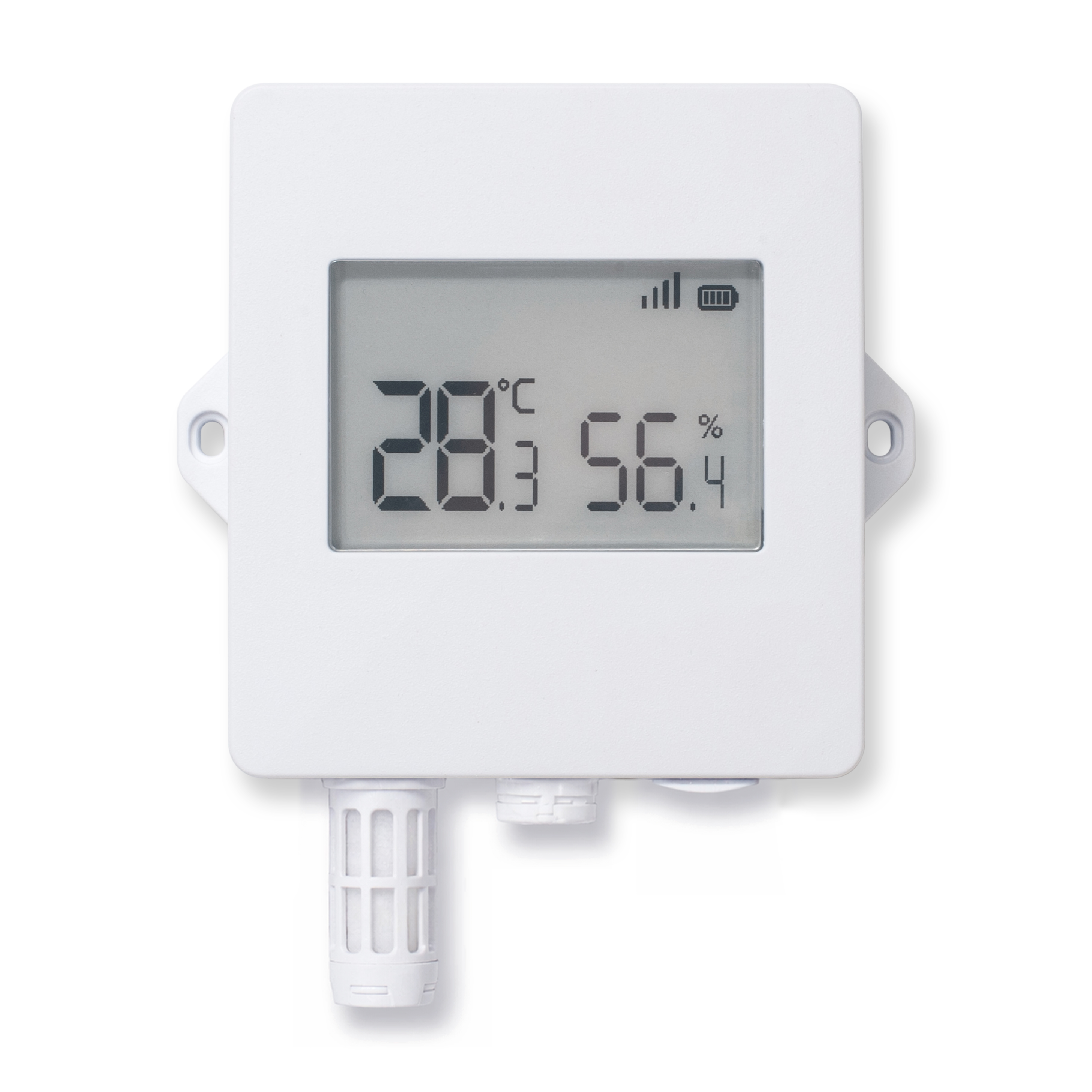
The Dragino S31B-LE is a LoRaWAN Temperature and Humidity Sensor for Internet of Things solution. It is used to measure the surrounding environment temperature and relative air humidity precisely, and then upload to IoT server via LoRaWAN wireless protocol.
The temperature & humidity sensor used in S31B-LE is SHT31, which is fully calibrated, linearized, and temperature compensated digital output from Sensirion, it provides a strong reliability and long-term stability. The SHT31 is fixed in a waterproof anti-condensation casing for long term use.
The LoRa wireless technology used in S31B-LE allows device to send data and reach extremely long ranges at low data-rates. It provides ultra-long range spread spectrum communication and high interference immunity whilst minimizing current consumption.
S31B-LE supports Temperature & Humdity alarm feature, user can set temperature alarm for instant notice. S31B-LE supports Datalog feature, it can save the data when there is no LoRaWAN network and uplink when network recover.
S31B-LE supports BLE configure and wireless OTA update which make user easy to use.
S31B-LE is powered by 8000mAh Li-SOCI2 battery,it is designed for long term use up to 5 years.
Each S31B-LE is pre-load with a set of unique keys for LoRaWAN registrations, register these keys to local LoRaWAN server and it will auto connect after power on.
1.2 Features
- LoRaWAN 1.0.3 Class A
- Ultra-low power consumption
- Measure range 0°C ~ 50°C
- Temperature & Humidity alarm
- Bands: CN470/EU433/KR920/US915/EU868/AS923/AU915/IN865
- Support Bluetooth v5.1 and LoRaWAN remote configure
- Support wireless OTA update firmware
- Uplink on periodically
- Downlink to change configure
- 8000mAh Li/SOCl2 Battery
The SHT31 sensing element supports -40 ~ +80°C, but the S31B-FE overall measurement range is 0 ~ 50°C, limited by the 2.7" E-Ink display operating temperature range
1.3 Specification
Common DC Characteristics:
- Supply Voltage: Built-in Battery , 2.5v ~ 3.6v
- Operating Temperature: 0 ~ 50°C
Temperature Sensor:
- Range: -40 to + 80°C
- Accuracy: ±0.2 @ 0-90 °C
- Resolution: 0.1°C
- Long Term Shift: <0.03 °C/yr
Humidity Sensor:
- Range: 0 ~ 99.9% RH
- Accuracy: ± 2%RH ( 0 ~ 100%RH)
- Resolution: 0.01% RH
- Long Term Shift: <0.25 %RH/yr
LoRa Spec:
- Frequency Range, Band 1 (HF): 862 ~ 1020 Mhz
- Max +22 dBm constant RF output vs.
- RX sensitivity: down to -139 dBm.
- Excellent blocking immunity
Battery:
- Li/SOCI2 un-chargeable battery
- Capacity: 8000mAh
- Self-Discharge: <1% / Year @ 25°C
- Max continuously current: 130mA
- Max boost current: 2A, 1 second
Power Consumption:
- Sleep Mode: 5uA @ 3.3v
- LoRa Transmit Mode: 125mA @ 20dBm, 82mA @ 14dBm
1.4 Sleep mode and working mode
Deep Sleep Mode: Sensor doesn't have any LoRaWAN activate. This mode is used for storage and shipping to save battery life.
Working Mode: In this mode, Sensor will work as LoRaWAN Sensor to Join LoRaWAN network and send out sensor data to server. Between each sampling/tx/rx periodically, sensor will be in IDLE mode), in IDLE mode, sensor has the same power consumption as Deep Sleep mode.
1.5 Button & LEDs
| Behavior on ACT | Function | Action |
|---|---|---|
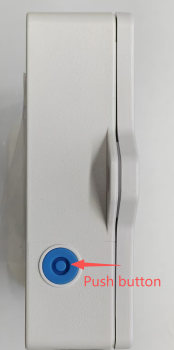
 1~3s 1~3s | Send an uplink | If sensor is already Joined to LoRaWAN network, sensor will send an uplink packet, blue led will blink once. Meanwhile, BLE module will be active and user can connect via BLE to configure device. |
| >3s | Active Device | Green led will fast blink 5 times, device will enter OTA mode for 3 seconds. And then start to JOIN LoRaWAN network. Green led will solidly turn on for 5 seconds after joined in network. Once sensor is active, BLE module will be active and user can connect via BLE to configure device, no matter if device join or not join LoRaWAN network. |
 x5 x5 | Deactivate Device | Red led will solid on for 5 seconds. Means device is in Deep Sleep Mode. |
1.6 BLE connection
S31B-LE support BLE remote configure.
BLE can be used to configure the parameter of sensor or see the console output from sensor. BLE will be only activate on below case:
- Press button to send an uplink
- Press button to active device.
- Device Power on or reset.
If there is no activity connection on BLE in 60 seconds, sensor will shut down BLE module to enter low power mode.
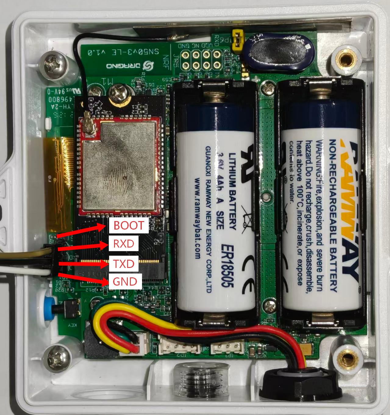
1.7 Pin Definitions
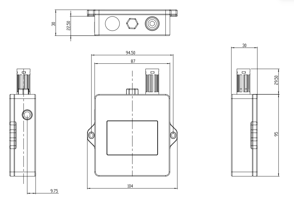
1.8 Mechanical
1.9. Meaning of E-Ink screen icons
Device mode icons
| Mode | Screen icon |
|---|---|
| Deep Sleep Mode | 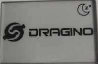 |
| Joining LoRaWAN network Mode | 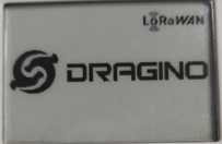 |
Signal strength
| Signal strength | Signal icon |
|---|---|
| RSSI greater than -55 |  |
| RSSI greater than -75 and less than or equal to -55 |  |
| RSSI greater than -90 and less than or equal to -75 |  |
| RSSI value less than or equal to -90 |  |
Battery percentage
| Battery percentage | Battery icon |
|---|---|
| Greater than 75% and less than or equal to 100% |  |
| Greater than 50% and less than or equal to 75% |  |
| Greater than 25% and less than or equal to 50% |  |
| Less than or equal to 25% |  |
2. Configure S31B-LE to connect to LoRaWAN network
2.1 How it works
The S31B-LE is configured as LoRaWAN OTAA Class A mode by default. It has OTAA keys to join LoRaWAN network. To connect a local LoRaWAN network, you need to input the OTAA keys in the LoRaWAN IoT server and press the button to activate the S31B-LE. It will automatically join the network via OTAA and start to send the sensor value. The default uplink interval is 20 minutes.
2.2 Quick guide to connect to LoRaWAN server (OTAA)
Following is an example for how to join the TTN v3 LoRaWAN Network. Below is the network structure; we use the LPS8v2 as a LoRaWAN gateway in this example.
The LPS8V2 is already set to connected to TTN network , so what we need to now is configure the TTN server.
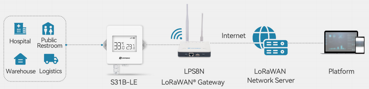
Step 1: Create a device in TTN with the OTAA keys from S31B-LE.
Each S31B-LE is shipped with a sticker with the default device EUI as below:
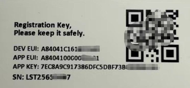
You can enter this key in the LoRaWAN Server portal. Below is TTN screen shot:
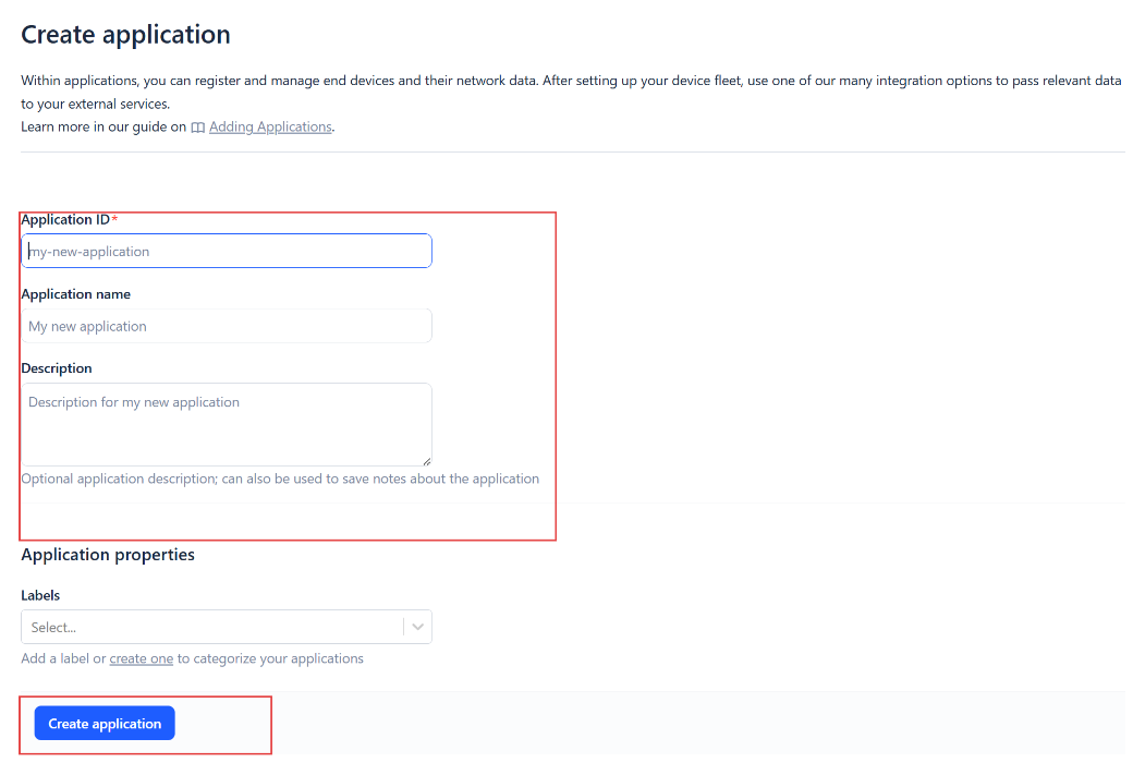
Create the application.

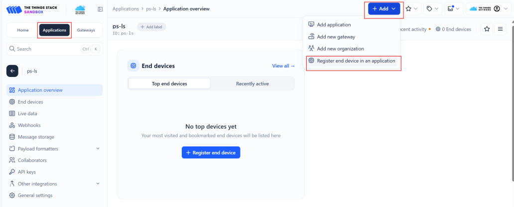
Add devices to the created Application.
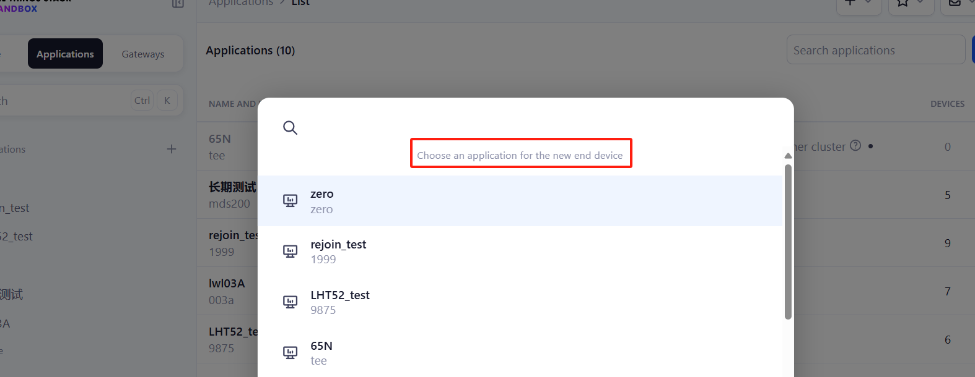
Enter end device specifics manually.
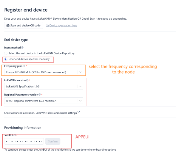
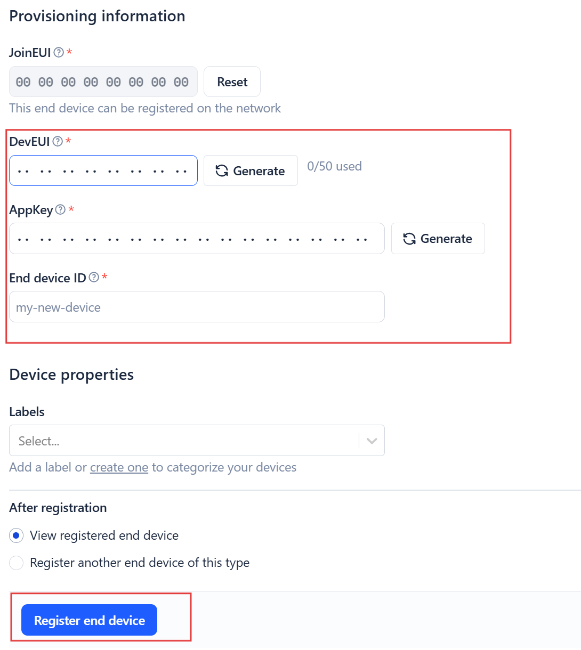
Add DevEUI and AppKey. Customize a platform ID for the device.
Step 2: Add decoder.
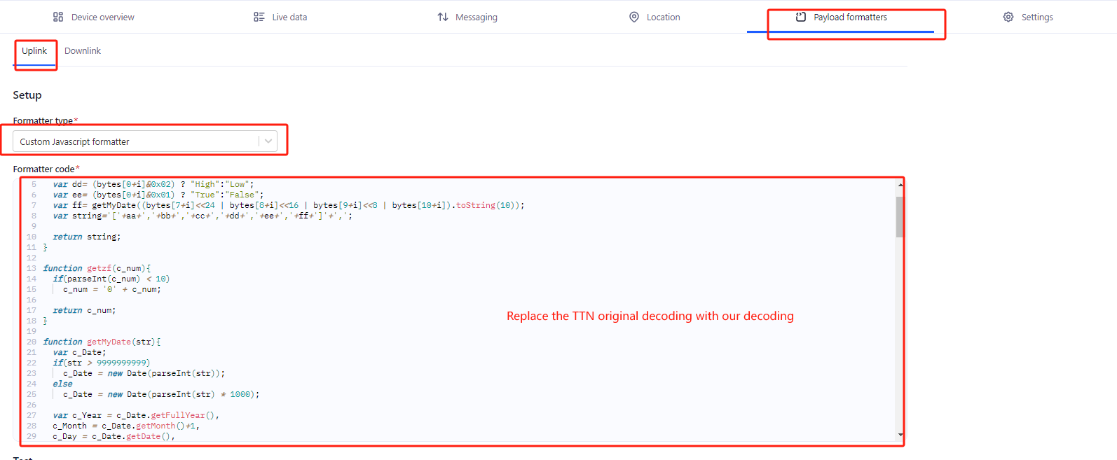
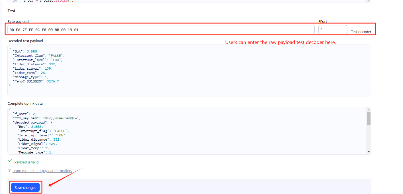
In TTN, user can add a custom payload so it shows friendly reading.
Click this link to get the decoder: S31B-LE decoder
Below is TTN screen shot:
Step 3: Activate on S31B-LE
Press the button for 5 seconds to activate the S31B-LE.
Green led will fast blink 5 times, device will enter OTA mode for 3 seconds. And then start to JOIN LoRaWAN network. Green led will solidly turn on for 5 seconds after joined in network.
After join success, it will start to upload messages to TTN and you can see the messages in the panel.
2.3 Uplink Payload
2.3.1 Device Status, FPORT=5
Users can use the downlink command(0x26 01) to ask S31B-LE to send device configure detail, include device configure status. S31B-LE will uplink a payload via FPort=5 to server.
The Payload format is as below.
| Device Status (FPORT=5) | |||||
| Size (bytes) | 1 | 2 | 1 | 1 | 2 |
| Value | Sensor Model | Firmware Version | Frequency Band | Sub-band | BAT |
Example parse in TTNv3

Sensor Model: For , this value is 0x0A
Firmware Version: 0x0100, Means: v1.0.0 version
Frequency Band:
0x01: EU868
0x02: US915
0x03: IN865
0x04: AU915
0x05: KZ865
0x06: RU864
0x07: AS923
0x08: AS923-1
0x09: AS923-2
0x0a: AS923-3
0x0b: CN470
0x0c: EU433
0x0d: KR920
0x0e: MA869
Sub-Band:
AU915 and US915:value 0x00 ~ 0x08
CN470: value 0x0B ~ 0x0C
Other Bands: Always 0x00
Battery Info:
Check the battery voltage.
Ex1: 0x0CD8 = 3288mV
Ex2: 0x0B49 = 2889mV
2.3.2 Sensor Data. FPORT=2
Sensor Data is uplink via FPORT=2
| Size(bytes) | 2 | 4 | 1 | 2 | 2 |
|---|---|---|---|---|---|
| Value | Battery | Unix TimeStamp & Sensor | EXTI_Trigger & Door_status & MOD | TempC_SHT | Hum_SHT |

Battery
Sensor Battery Level.
Ex1: 0x0CD8 = 3288mV
Ex2: 0x0B49 = 2889mV
EXTI_Trigger & Door_status & MOD
Example:
If (payload & 0x7C)>>2 = 0x00 --> means MOD=0, This is a sampling uplink message.
If (payload & 0x7C)>>2 = 0x31 --> means MOD=31, this message is a reply message for polling, this message contains the alarm settings. see this link for detail.
If payload & 0x02 = 0x00 --> The SENSOR is SHT3X.
If payload & 0x02 = 0x01 --> The SENSOR is SHT4X.
If payload & 0x01 = 0x00 --> This means that the EXTI_Trigger status is FALSE.
If payload & 0x01 = 0x01 --> This means that the EXTI_Trigger status is TRUE.
If payload & 0x80 = 0x00 --> This means that the Door_status is OPEN.
If payload & 0x80 = 0x01 --> This means that the Door_status is CLOSE.
Temperature
Example:
If payload is: 00FBH: (00FB & 8000 == 0), temp = 00FBH /10 = 25.1 degree
If payload is: FF3FH : (FF3F & 8000 == 1) , temp = (FF3FH - 65536)/10 = -19.3 degrees.
(FF3F & 8000:Judge whether the highest bit is 1, when the highest bit is 1, it is negative)
Humidity
Read:0x(0210)=528 Value: 528 / 10=52.8, So 52.8%
2.4 Payload Decoder file
In TTN, use can add a custom payload so it shows friendly reading
In the page Applications --> Payload Formats --> Custom --> decoder to add the decoder from:
2.5 Datalog Feature
Datalog Feature is to ensure IoT Server can get all sampling data from Sensor even if the LoRaWAN network is down. For each sampling, S31B-LE will store the reading for future retrieving purposes.
2.5.1 How datalog works
S31B-LE will wait for ACK for every uplink, when there is no LoRaWAN network,S31B-LE will mark these records with non-ack messages and store the sensor data, and it will send all messages (10s interval) after the network recovery.
a) S31B-LE will do an ACK check for data records sending to make sure every data arrive server.
b) S31B-LE will send data in CONFIRMED Mode, but S31B-LE won't re-transmit the packet if it doesn't get ACK, it will just mark it as a NONE-ACK message. In a future uplink if S31B-LE gets a ACK, S31B-LE will consider there is a network connection and resend all NONE-ACK messages.
2.5.2 Enable Datalog
User need to make sure below two settings are enable to use datalog;
- SYNCMOD=1(Default) to enable sync time via LoRaWAN MAC command, click here (AT+SYNCMOD) for detailed instructions.
- PNACKMD=1 to enable datalog feature, click here (AT+PNACKMD) for detailed instructions.
Once S31B-LE Joined LoRaWAN network, it will send the MAC command (DeviceTimeReq) and the server will reply with (DeviceTimeAns) to send the current time to S31B-LE. If S31B-LE fails to get the time from the server, S31B-LE will use the internal time and wait for next time request (AT+SYNCTDC to set the time request period, default is 10 days).
Note: LoRaWAN Server need to support LoRaWAN v1.0.3(MAC v1.0.3) or higher to support this MAC command feature, Chirpstack,TTN V3 v3 and loriot support but TTN V3 v2 doesn't support. If server doesn't support this command, it will through away uplink packet with this command, so user will lose the packet with time request for TTN V3 v2 if SYNCMOD=1.
2.5.3 Unix TimeStamp
S31B-LE uses Unix TimeStamp format based on
-a102bf3437d8e74cadc69b93cd1f79a6.png)
User can get this time from link: TimeStamp :
Below is the converter example
-bacdb57bb3ddf9fe164fb644989cd68e.png)
2.5.4 Datalog Uplink payload (FPORT=3)
The Datalog uplinks will use below payload format.
Retrieval data payload:
| Size(bytes) | 2 | 2 | 2 | 1 | 4 |
|---|---|---|---|---|---|
| Value | ignore | Humidity | Temperature | Poll message flag & Alarm Flag& Level of PA15 | Unix Time Stamp |
Poll message flag & Alarm Flag & Level of PA15:

No ACK Message: 1: This message means this payload is fromn Uplink Message which doesn't get ACK from the server before ( for PNACKMD=1 feature)
Poll Message Flag: 1: This message is a poll message reply.
-
Poll Message Flag is set to 1.
-
Each data entry is 11 bytes, to save airtime and battery, devices will send max bytes according to the current DR and Frequency bands.
For example, in US915 band, the max payload for different DR is:
a) DR0: max is 11 bytes so one entry of data
b) DR1: max is 53 bytes so devices will upload 4 entries of data (total 44 bytes)
c) DR2: total payload includes 11 entries of data
d) DR3: total payload includes 22 entries of data.
If devise doesn't have any data in the polling time. Device will uplink 11 bytes of 0
Example:
If S31B-LE has below data inside Flash:
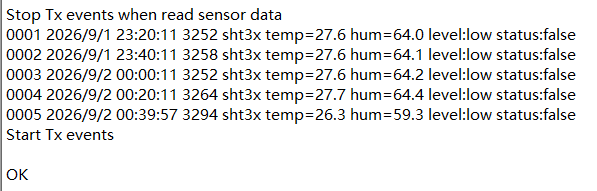
If user sends below downlink command: 316A975DA06A97706005
Where :
-
Start time: 6A975DA0 = time 2026/9/1 23:20:00
-
Stop time: 6A977060 = time 2026/9/2 00:40:00
S31B-LE will uplink this payload.
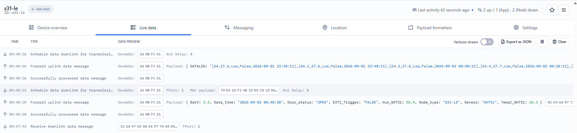
000002800114406A975DAB 000002810114406A97625B 000002820114406A97670B 000002840115406A976BBB 000002510107406A97705D
Where the first 11 bytes is for the first entry:
00 00 02 80 01 14 40 6A 97 5D AB
ignore = 0x0000
Hum = 0x0280/10=64.0%
Temp = 0x0114/10=27.6℃
poll message flag & Alarm Flag & Level of PA15 =0x40,means reply data,sampling uplink message,the PA15 is low level.
Unix time is 0x6A975DAB=1684899041s=2026/9/1 23:20:11
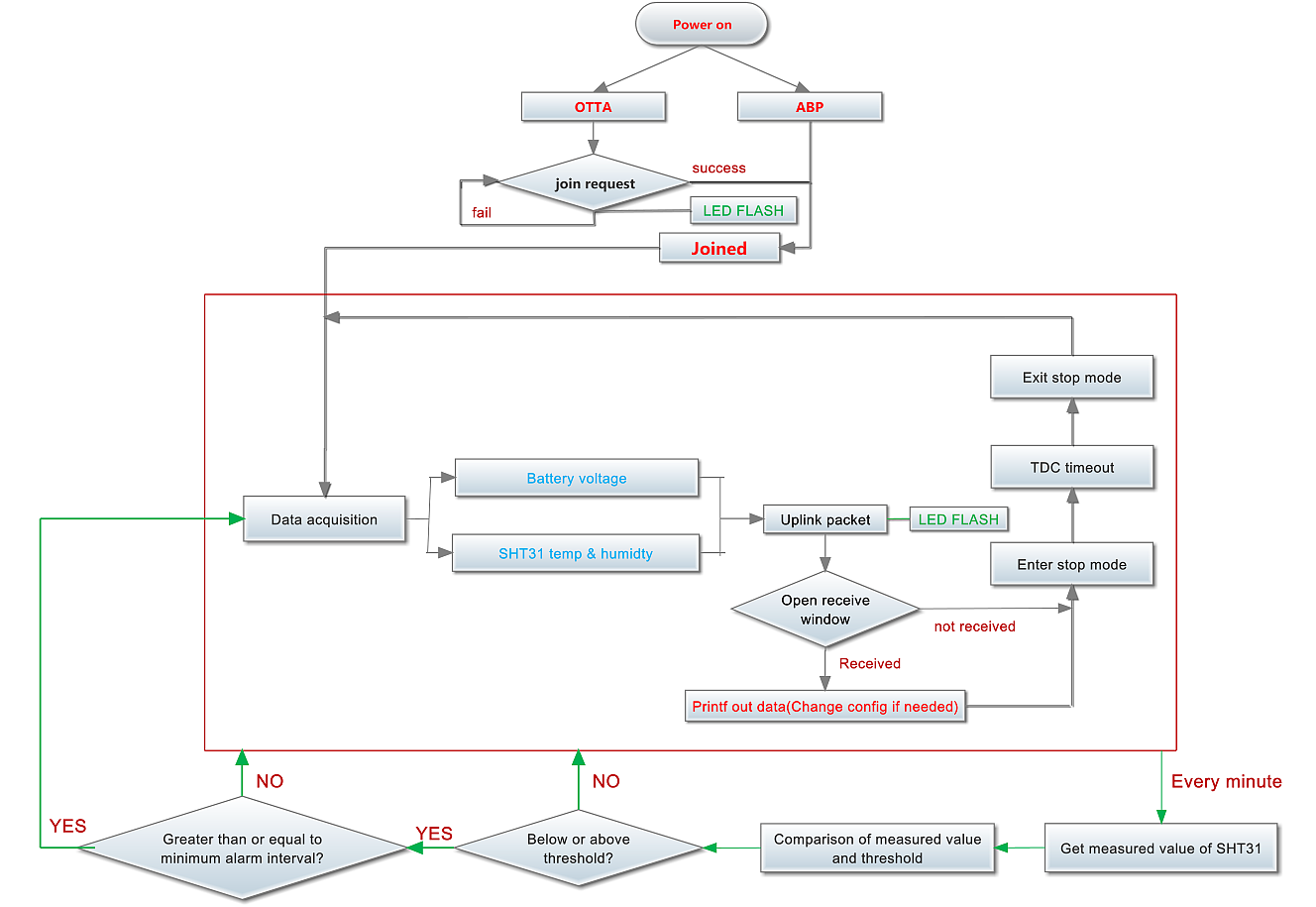
2.6 Temperature Alarm Feature
S31B-LE work flow with Alarm feature.
2.7 Frequency Plans
The S31B-LE uses OTAA mode and below frequency plans by default. Each frequency band use different firmware, user update the firmware to the corresponding band for their country.
2.8 Firmware Change Log
Firmware download link: https://www.dropbox.com/sh/fis3g6nmhv0eokg/AAC6BcCZaX4BdqZkduUvZ3jIa?dl=0
3. Configure S31B-LE
3.1 Configure Methods
S31B-LE supports below configure method:
- AT Command via Bluetooth Connection (Recommended): BLE Configure Instruction.
- AT Command via UART Connection : See UART Connection.
- LoRaWAN Downlink. Instruction for different platforms: See IoT LoRaWAN Server section.
3.2 General Commands
These commands are to configure:
- General system settings like: uplink interval.
- LoRaWAN protocol & radio related command.
They are same for all Dragino Devices which support DLWS-005 LoRaWAN Stack. These commands can be found on the wiki:
/docs/LoRaWAN-General-Configuration/at-commands-downlink/
3.3 Commands special design for S31B-LE
These commands only valid for S31B-LE, as below:
3.3.1 Set Transmit Interval Time
Feature: Change LoRaWAN End Node Transmit Interval.
AT Command: AT+TDC
| Command Example | Function | Response |
|---|---|---|
| AT+TDC=? | Show current transmit Interval | 30000 OK the interval is 30000ms = 30s |
| AT+TDC=60000 | Set Transmit Interval | OK Set transmit interval to 60000ms = 60 seconds |
Downlink Command: 0x01
Format: Command Code (0x01) followed by 3 bytes time value.
If the downlink payload=0100003C, it means set the END Node's Transmit Interval to 0x00003C=60(S), while type code is 01.
- Example 1: Downlink Payload: 0100001E // Set Transmit Interval (TDC) = 30 seconds
- Example 2: Downlink Payload: 0100003C // Set Transmit Interval (TDC) = 60 seconds
3.3.2 Get Device Status
Send a LoRaWAN downlink to ask device send Alarm settings.
Downlink Payload: 0x26 01
Sensor will upload Device Status via FPORT=5. See payload section for detail.
3.3.3 Set Temperature Alarm Threshold
- AT Command:
AT+SHTEMP=min,max
- When min=0, and max≠0, Alarm higher than max
- When min≠0, and max=0, Alarm lower than min
- When min≠0 and max≠0, Alarm higher than max or lower than min
Example:
AT+SHTEMP=0,30 // Alarm when temperature higher than 30.
- Downlink Payload:
0x(0C 01 00 1E) // Set AT+SHTEMP=0,30 (note: 3rd byte= 0x00 for low limit(not set), 4th byte = 0x1E for high limit: 30)
3.3.4 Set Humidity Alarm Threshold
- AT Command:
AT+SHHUM=min,max
- When min=0, and max≠0, Alarm higher than max
- When min≠0, and max=0, Alarm lower than min
- When min≠0 and max≠0, Alarm higher than max or lower than min
Example:
AT+SHHUM=70,0 // Alarm when humidity lower than 70%.
- Downlink Payload:
0x(0C 02 46 00) // Set AT+SHTHUM=70,0 (note: 3rd byte= 0x46 for low limit (70%), 4th byte = 0x00 for high limit (not set))
3.3.5 Set Alarm Interval
The shortest time of two Alarm packet. (unit: min)
- AT Command:
AT+ATDC=30 // The shortest interval of two Alarm packets is 30 minutes, Means is there is an alarm packet uplink, there won't be another one in the next 30 minutes.
- Downlink Payload:
0x(0D 00 1E) ---> Set AT+ATDC=0x 00 1E = 30 minutes
3.3.6 Get Alarm settings
Send a LoRaWAN downlink to ask device send Alarm settings.
- Downlink Payload: 0x0E 01
Example:
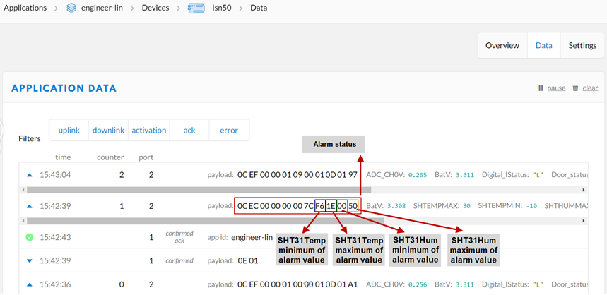
Explain:
- Alarm & MOD bit is 0x7C, 0x7C >> 2 = 0x31: Means this message is the Alarm settings message.
3.3.7 Set Interrupt Mode
Feature, Set Interrupt mode for PA15 of pin.
When AT+INTMOD=0 is set, PA15 is used as a digital input port.
AT Command: AT+INTMOD
| Command Example | Function | Response |
|---|---|---|
| AT+INTMOD=? | Show current interrupt mode | 0 OK the mode is 0 =Disable Interrupt |
| AT+INTMOD=2 | 0: Disable Interrupt 1: Trigger by rising and falling edge 2: Trigger by falling edge 3: Trigger by rising edge | OK |
Downlink Command: 0x06
Format: Command Code (0x06) followed by 3 bytes.
This means that the interrupt mode of the end node is set to 0x000003=3 (rising edge trigger), and the type code is 06.
- Example 1: Downlink Payload: 06000000 // Turn off interrupt mode
- Example 2: Downlink Payload: 06000003 // Set the interrupt mode to rising edge trigger
3.3.8 Set Power Output Duration
Control the output duration 5V . Before each sampling, device will
1. first enable the power output to external sensor,
2. keep it on as per duration, read sensor value and construct uplink payload
3. final, close the power output.
AT Command: AT+5VT
| Command Example | Function | Response |
|---|---|---|
| AT+5VT=? | Show 5V open time. | 0 (default) OK |
| AT+5VT=1000 | Close after a delay of 1000 milliseconds. | OK |
Downlink Command: 0x07
Format: Command Code (0x07) followed by 2 bytes.
The first and second bytes are the time to turn on.
- Example 1: Downlink Payload: 070000 //Same as AT+5VT=0
- Example 2: Downlink Payload: 0701F4 //Same as AT+5VT=500
3.3.9 Print data entries base on page
Feature: Print the sector data from start page to stop page (max is 416 pages).
AT Command: AT+PDTA
| Command Example | Function |
|---|---|
| AT+PDTA=1,1 Print page 1 to 1 | Stop Tx events when read sensor data 8037900 2026/9/1 23:00:11 3300 sht3x temp=27.6 hum=63.9 level:low status:false 8037910 2026/9/1 23:20:11 3252 sht3x temp=27.6 hum=64.0 level:low status:false 8037920 2026/9/1 23:40:11 3258 sht3x temp=27.6 hum=64.1 level:low status:false 8037930 2026/9/2 00:00:11 3252 sht3x temp=27.6 hum=64.2 level:low status:false 8037940 2026/9/2 00:20:11 3264 sht3x temp=27.7 hum=64.4 level:low status:false 8037950 2026/9/2 00:39:57 3294 sht3x temp=26.3 hum=59.3 level:low status:false 8037960 2026/9/2 00:48:30 3300 sht3x temp=26.3 hum=55.9 level:low status:false 8037970 2026/9/2 01:04:40 3300 sht3x temp=25.7 hum=52.9 level:low status:false 8037980 2026/9/2 01:20:25 3612 sht3x temp=25.7 hum=57.3 level:low status:false 8037990 2026/9/2 01:40:25 3306 sht3x temp=25.2 hum=49.7 level:low status:false Start Tx events OK |
Downlink Command:
No downlink commands for feature
3.3.10 Print last few data entries
Feature: Print the last few data entries
AT Command: AT+PLDTA
| Command Example | Function |
|---|---|
| AT+PLDTA=5 Print last 5 entries | Stop Tx events when read sensor data 0001 2026/9/2 00:39:57 3294 sht3x temp=26.3 hum=59.3 level:low status:false 0002 2026/9/2 00:48:30 3300 sht3x temp=26.3 hum=55.9 level:low status:false 0003 2026/9/2 01:04:40 3300 sht3x temp=25.7 hum=52.9 level:low status:false 0004 2026/9/2 01:20:25 3612 sht3x temp=25.7 hum=57.3 level:low status:false 0005 2026/9/2 01:40:25 3306 sht3x temp=25.2 hum=49.7 level:low status:false Start Tx events OK |
Downlink Command:
No downlink commands for feature
3.3.11 Clear Flash Record
Feature: Clear flash storage for data log feature.
AT Command: AT+CLRDTA
| Command Example | Function | Response |
|---|---|---|
| AT+CLRDTA | Clear date record | Clear all stored sensor data… OK |
Downlink Command: 0xA3
- Example: 0xA301 // Same as AT+CLRDTA
4. Battery & Power Consumption
S31B-LE use 2 × ER18505 battery pack. See below link for detail information about the battery info and how to replace.
5. OTA Firmware update
User can change firmware S31B-LE to:
- Change Frequency band/ region.
- Update with new features.
- Fix bugs.
Firmware and changelog can be downloaded from : Firmware download link
Methods to Update Firmware:
- (Recommended way) OTA firmware update via wireless: Firmware OTA Update for LoRaWAN End Node
- Update through UART TTL interface : Instruction.
6. FAQ
7. Order Info
Part Number: S31B-LE-XX
XX: The default frequency band
-
AS923: LoRaWAN AS923 band
-
AU915: LoRaWAN AU915 band
-
EU433: LoRaWAN EU433 band
-
EU868: LoRaWAN EU868 band
-
KR920: LoRaWAN KR920 band
-
US915: LoRaWAN US915 band
-
IN865: LoRaWAN IN865 band
-
CN470: LoRaWAN CN470 band
8. Packing Info
Package Includes:
- S31B-LE LoRaWAN Temperature & Humidity Sensor
Dimension and weight:
-
Package Size / pcs : mm
-
Weight / pcs : g
9. Support
-
Support is provided Monday to Friday, from 09:00 to 18:00 GMT+8. Due to different timezones we cannot offer live support. However, your questions will be answered as soon as possible in the before-mentioned schedule.
-
Provide as much information as possible regarding your enquiry (product models, accurately describe your problem and steps to replicate it etc) and send a mail to Support@dragino.cc.