SVC01-LS2
1. Introduction
1.1 What is SVC01-LS2 LoRaWAN Solenoid Valve Controller
The Dragino SVC01-LS2 is a LoRaWAN Solenoid Valve Controller designed for smart irrigation. SVC01-LS2 has the capability to control 2 of Solenoid Valve and able to get pulse count from water flow sensor. With these two features, SVC01-LS2 is suitable to be used in the remote water monitoring and controlling.
SVC01-LS2 supports BLE configure and wireless OTA update which make user easy to use.
SVC01-LS2 is powered by 19000mAh Li-SOCI2 battery or solar powered + Li-ion battery or 12 VDC power supply.
Each SVC01-LS2 is pre-load with a set of unique keys for LoRaWAN registrations, register these keys to local LoRaWAN server and it will auto connect after power on.
1.2 Features
- LoRaWAN: Version 1.0.3
- Valve Control: 2-channel solenoid valve control
- Valve Drive Capability: Supports DC 9V-12V latching pulse solenoid valves
- Maximum Drive Current: 1.5A
- Compatibility: TORO P150, PGV101 (9V DC), and other irrigation pulse valves
- Water Measurement: 2-channel pulse counting for water volume measurement
- Irrigation Scheduling: Configurable timed irrigation
- Battery: 10000 mAh Li-ion rechargeable battery
- Solar Panel: 1.2 W
- Ingress Protection: IP67 rated
- Durability Feature: Air pressure balance to sustain operation in tough environments
1.3 Specification
Common DC Characteristics:
- Supply Voltage: Built-in Battery, 2.8v ~ 3.6v
- Operating Temperature: -40 ~ 85°C
LoRa Spec:
- Frequency Range, Band 1 (HF): 862 ~ 1020 Mhz
- Max +22 dBm constant RF output vs.
- RX sensitivity: down to -139 dBm.
- Excellent blocking immunity
Battery:
- Li/SOCI2 un-chargeable battery
- Capacity: 19000mAh
- Self-Discharge: <1% / Year @ 25°C
- Max continuously current: 130mA
- Max boost current: 2A, 1 second
- Li-ion rechargeable battery
- Capacity: 10000mAh
- Self-Discharge: <1% / Year @ 25°C
- Max continuously current: 130mA
- Max boost current: 2A, 1 second
Power Consumption
- Sleep Mode: 5uA @ 3.3v
- LoRa Transmit Mode: 125mA @ 20dBm, 82mA @ 14dBm
1.4 Sleep mode and working mode
Deep Sleep Mode: Sensor doesn't have any LoRaWAN activate. This mode is used for storage and shipping to save battery life.
Working Mode: In this mode, Sensor will work as LoRaWAN Sensor to Join LoRaWAN network and send out sensor data to server. Between each sampling/tx/rx periodically, sensor will be in IDLE mode), in IDLE mode, sensor has the same power consumption as Deep Sleep mode.
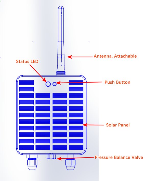
1.5 Button & LEDs
| Behavior on ACT | Function | Action |
|---|---|---|
| Send an uplink | If sensor is already Joined to LoRaWAN network, sensor will send an uplink packet, blue led will blink once. Meanwhile, BLE module will be active and user can connect via BLE to configure device. | |
| Active Device | Green led will fast blink 5 times, device will enter OTA mode for 3 seconds. And then start to JOIN LoRaWAN network. Green led will solidly turn on for 5 seconds after joined in network. Once sensor is active, BLE module will be active and user can connect via BLE to configure device, no matter if device join or not join LoRaWAN network. | |
| Deactivate Device | Red led will solid on for 5 seconds. Means device is in Deep Sleep Mode. |
1.6 BLE connection
SVC01-LS2 support BLE remote configure.
BLE can be used to configure the parameter of sensor or see the console output from sensor. BLE will be only activate on below case:
- Press button to send an uplink
- Press button to active device.
- Device Power on or reset.
If there is no activity connection on BLE in 60 seconds, sensor will shut down BLE module to enter low power mode.
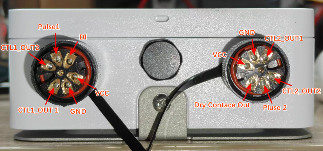
1.7 Pin Definitions
1.7.1 Pin Definitions
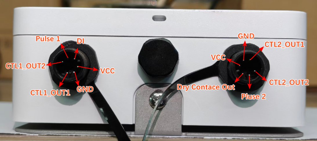
1.7.2 Connector Pin Definitions
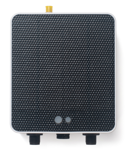
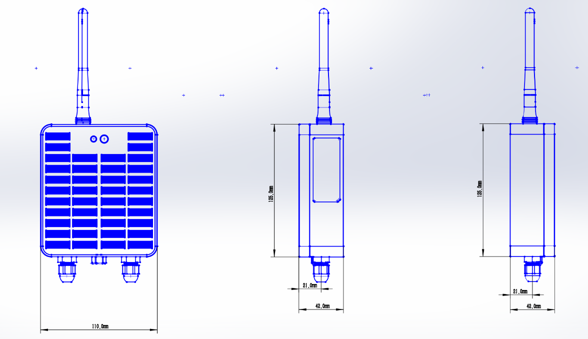
1.8 Mechanical
2. Configure SVC01-LS2 to connect to LoRaWAN network
2.1 How it works
The SVC01-LS2 is configured as LoRaWAN OTAA Class A mode by default. It has OTAA keys to join LoRaWAN network. To connect a local LoRaWAN network, you need to input the OTAA keys in the LoRaWAN IoT server and press the button to activate the SVC01-LS2. It will automatically join the network via OTAA and start to send the sensor value. The default uplink interval is 20 minutes.
2.2 Quick guide to connect to LoRaWAN server (OTAA)
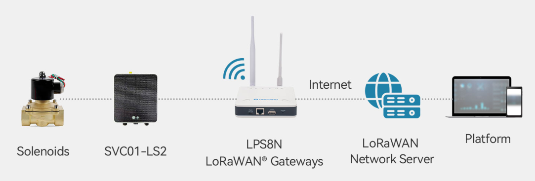
Following is an example for how to join the TTN v3 LoRaWAN Network. Below is the network structure; we use the LPS8v2 as a LoRaWAN gateway in this example.
The LPS8V2 is already set to connected to TTN network, so what we need to now is configure the TTN server.
Step 1: Create a device in TTN with the OTAA keys from SVC01-LS2.
Each SVC01-LS2 is shipped with a sticker with the default device EUI as below:
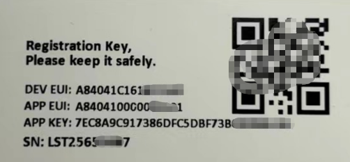
You can enter this key in the LoRaWAN Server portal. Below is TTN screen shot:
Create the application.
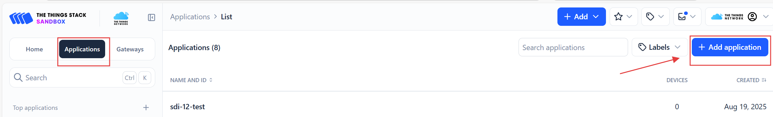
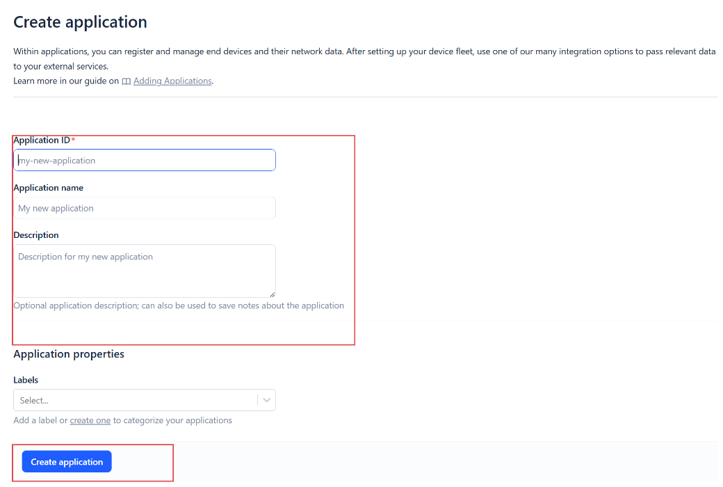
Add devices to the created Application.
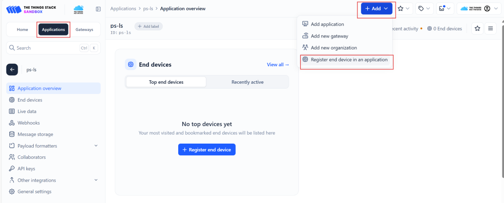
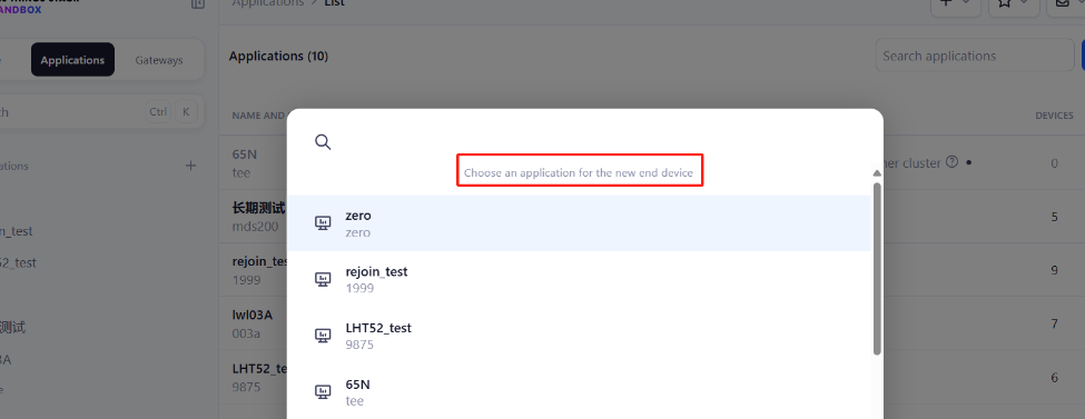
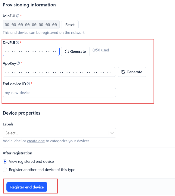
Enter end device specifics manually.
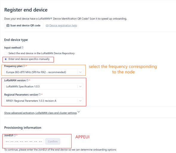
Add DevEUI and AppKey. Customize a platform ID for the device.
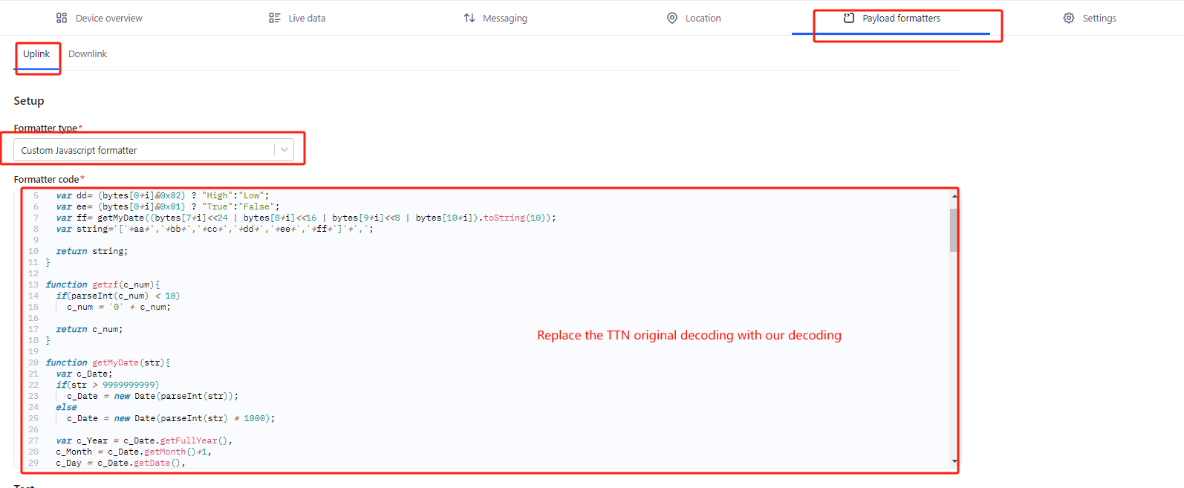
Step 2: Add decoder.
In TTN, user can add a custom payload so it shows friendly reading.
Click this link to get the decoder: https://github.com/dragino/dragino-end-node-decoder/tree/main/
Below is TTN screen shot:
Step 3: Activate on SVC01-LS2
Press the button for 5 seconds to activate the SVC01-LS2.
Green led will fast blink 5 times, device will enter OTA mode for 3 seconds. And then start to JOIN LoRaWAN network. Green led will solidly turn on for 5 seconds after joined in network.
After join success, it will start to upload messages to TTN and you can see the messages in the panel.
2.3 Uplink Payload
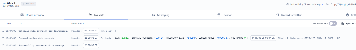
2.3.1 Device Status, FPORT=5
Users can use the downlink command(0x26 01) to ask SVC01-LS2 to send device configure detail, include device configure status. SVC01-LS2 will uplink a payload via FPort=5 to server.
The Payload format is as below.
| Device Status (FPORT=5) | |||||
| Size (bytes) | 1 | 2 | 1 | 1 | 2 |
| Value | Sensor Model | Firmware Version | Frequency Band | Sub-band | BAT |
Example parse in TTNv3
Sensor Model: For SVC01-LS2, this value is 0x4A
Firmware Version: 0x0100, Means: v1.0.0 version
Frequency Band:
0x01: EU868
0x02: US915
0x03: IN865
0x04: AU915
0x05: KZ865
0x06: RU864
0x07: AS923
0x08: AS923-1
0x09: AS923-2
0x0a: AS923-3
0x0b: CN470
0x0c: EU433
0x0d: KR920
0x0e: MA869
Sub-Band:
AU915 and US915:value 0x00 ~ 0x08
CN470: value 0x0B ~ 0x0C
Other Bands: Always 0x00
Battery Info:
Check the battery voltage.
Ex1: 0x0A3E = 2622mV
Ex2: 0x0B49 = 2889mV
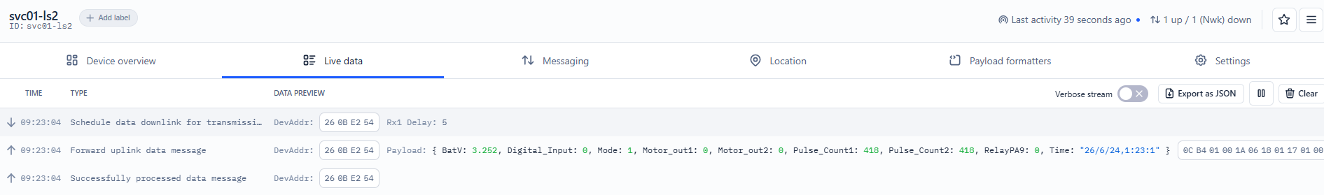
2.3.2 Working Modes & Sensor Data. Uplink via FPORT=2
2.3.2.1 MOD=1(Default Mode)
In this mode, uplink payload includes in total 19 bytes. Uplink packets use FPORT=2.
| Size(bytes) | 2 | 1 | 1 | 6 | 1 | 4 | 4 |
|---|---|---|---|---|---|---|---|
| Value | Battery | MOD | RelayPA9 & Motor_out1 & Motor_out2 | Time | Digital_Input | Pulse_Count1 | Pulse_Count2 |
Battery
Sensor Battery Level.
Ex1: 0x0A62 = 2658mV
Ex2: 0x0B49 = 2889mV
MOD
Example:
If payload is 0x01 = 0x01 --> The MOD is 1.
RelayPA9 & Motor_out1 & Motor_out2
Example:
RelayPA9: If payload is (0x40 >>1) & 0x01 = 0x00 --> The PA9 is Low level.
Motor_out1: If payload is (0x40 >>4) & 0x01 = 0x00 --> Indicates that Valve 1 is close.
Motor_out2: If payload is (0x40 >>5) & 0x01 = 0x00 --> Indicates that Valve 2 is close.
Time
Example:
If payload is 0x1A 06 0C 03 05 2D = 26/6/12,3:5:45
Digital_Input
If payload is 0x00 = 0 --> Digital_Input is Low level.
Pulse_Count1
If payload is 0x000001A2 = 418 --> Indicates that the Pulse1 count is 418.
Pulse_Count2
If payload is 0x000001A2 = 418 --> Indicates that the Pulse2 count is 418.
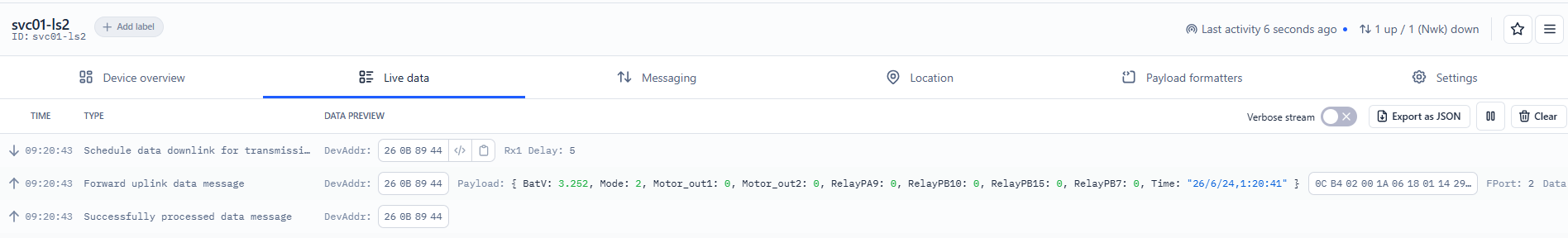
2.3.2.2 MOD=2(Relay Mode)
In this mode, uplink payload includes in total 10 bytes. Uplink packets use FPORT=2.
| Size(bytes) | 2 | 1 | 1 | 6 |
|---|---|---|---|---|
| Value | Battery | MOD | RelayPB10 & RelayPB15 & RelayPB7 & RelayPA9 & Motor_out1 & Motor_out2 | Time |
Battery
Sensor Battery Level.
Ex1: 0x0A62 = 2658mV
Ex2: 0x0B49 = 2889mV
MOD
If payload is 0x02 = 0x02 --> The MOD is 2.
RelayPB10 & RelayPB15 & RelayPB7 & RelayPA9 & Motor_out1 & Motor_out2
Example:
RelayPB10: If payload is (0x1A >>2) & 0x01 = 0x01 --> The RelayPB10 is high level.
RelayPB15: If payload is (0x1A >>3) & 0x01 = 0x01 --> The RelayPB15 is high level.
RelayPB7: If payload is 0x1A & 0x01 = 0x01 --> The RelayPB7 is high level.
RelayPA9: If payload is (0x1A >>1) & 0x01 = 0x01 --> The RelayPA9 is high level.
Motor_out1: If payload is (0x1A >>4) & 0x01 = 0x00 --> Indicates that Valve 1 is close.
Motor_out2: If payload is (0x1A >>5) & 0x01 = 0x00 --> Indicates that Valve 2 is close.
Time
Example:
If payload is 0x1A 06 17 0A 13 27 = 26/6/24,10:19:39
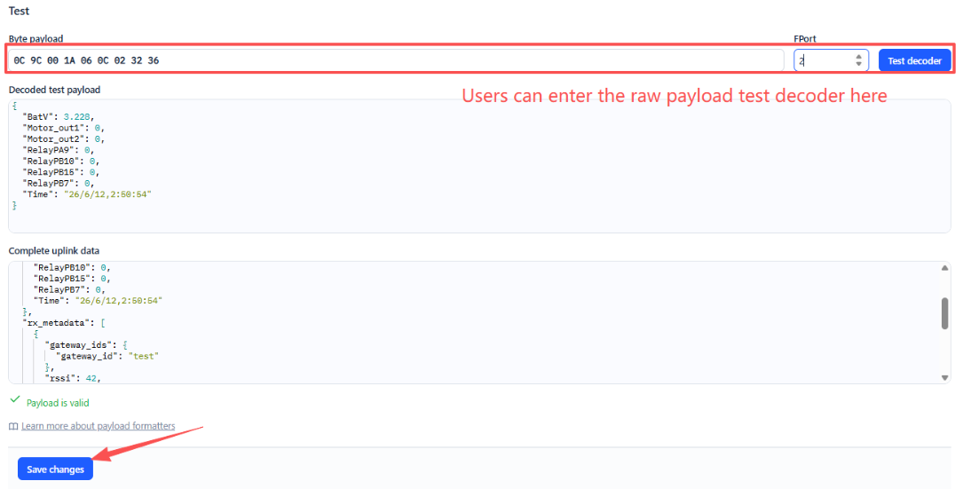
2.4 Payload Decoder file
In TTN, use can add a custom payload so it shows friendly reading
In the page Applications --> Payload Formats --> Custom --> decoder to add the decoder from:
https://github.com/dragino/dragino-end-node-decoder/tree/main/SVC01-L
2.5 Frequency Plans
The SVC01-LS2 uses OTAA mode and below frequency plans by default. Each frequency band use different firmware, user update the firmware to the corresponding band for their country.
2.6 Firmware Change Log
Firmware download link: To be updated
3. Configure SVC01-LS2
3.1 Configure Methods
SVC01-LS2 supports below configure method:
- AT Command via Bluetooth Connection (Recommended): BLE Configure Instruction.
- AT Command via UART Connection : See UART Connection.
- LoRaWAN Downlink. Instruction for different platforms: See IoT LoRaWAN Server section.
3.2 General Commands
These commands are to configure:
- General system settings like: uplink interval.
- LoRaWAN protocol & radio related command.
They are same for all Dragino Devices which support DLWS-005 LoRaWAN Stack. These commands can be found on the wiki:
/docs/Configuration/end-node/at-commands-downlink/
3.3 Commands special design for SVC01-LS2
These commands only valid for SVC01-LS2, as below:
3.3.1 Set Transmit Interval Time
Feature: Change LoRaWAN End Node Transmit Interval.
AT Command: AT+TDC
| Command Example | Function | Response |
|---|---|---|
| AT+TDC=? | Show current transmit Interval | 30000 OK the interval is 30000ms = 30s |
| AT+TDC=60000 | Set Transmit Interval | OK Set transmit interval to 60000ms = 60 seconds |
Downlink Command: 0x01
Format: Command Code (0x01) followed by 3 bytes time value.
If the downlink payload=0100003C, it means set the END Node's Transmit Interval to 0x00003C=60(S), while type code is 01.
- Example 1: Downlink Payload: 0100001E // Set Transmit Interval (TDC) = 30 seconds
- Example 2: Downlink Payload: 0100003C // Set Transmit Interval (TDC) = 60 seconds
3.3.2 Get Device Status
Send a LoRaWAN downlink to ask device send Alarm settings.
Downlink Payload: 0x26 01
Sensor will upload Device Status via FPORT=5. See payload section for detail.
3.3.3 Set the pulse time
Feature: Get or set the pulse time of the valve(ms)
Note: For this feature, it is recommended that the pulse duration for valves 1 and 2 be set to 20 ms (default). Increasing the pulse duration will increase power consumption.
AT Command: AT+MVT
| Command Example | Function | Response |
|---|---|---|
| AT+MVT=? | Show current parameters | 20,20 OK |
| AT+MVT=Motor_out1,Motor_out2 Ex1: AT+MVT=20,20 | Configure the pulse duration for Valve 1 and Valve 2 | OK |
Downlink Command: 0xA1
Format: Command Code (0xA1) followed by 4 bytes.
This means that the pulse times for Valves 1 and 2 on the terminal node are set to 0x00140014 = 20,20, with a type code of A1.
- Example 1: Downlink Payload: A100140014 // Same as AT+MVT=20,20
- Example 2: Downlink Payload: A100280028 // Same as AT+MVT=40,40
3.3.4 Set sd3178 time
Feature: Get or Set sd3178 time in second
Note: We recommend using the automatic time synchronization feature, as manually set times may differ slightly from the actual time.
AT Command: AT+SDTIME
| Command Example | Function | Response |
|---|---|---|
| AT+SDTIME=? | Get the current time | 26/06/12 09:20:37 - w5 OK |
| AT+SDTIME=1 | Set to automatic time synchronization | OK |
Downlink Command: 0xA3
Format: Command Code (0xA3) followed by 1 or 7 bytes.
This means that the endpoints are configured manually or set to automatic synchronization, with a type code of A3.
- Example 1: Downlink Payload: A3 01 // Same as AT+SDTIME=1, Set to automatic time synchronization
- Example 2: Downlink Payload: A3 1A 06 0C 09 14 25 05 // Same as AT+SDTIME=26,06,12,09,20,36,5, Configured on: 06/26/12 09:20:36 - w5
3.3.5 Set Workmode
Feature: Switch working mode.
AT Command: AT+MOD
| Command Example | Function | Response |
|---|---|---|
| AT+MOD=? | Get the current working mode | 1(Default) OK |
| AT+MOD=2 | 1. Counting + Relay Mode 2. 4-Channel Relay Mode | OK Attention:Take effect after ATZ |
Downlink Command: 0x0A
Format: Command Code (0x0A) followed by 1 bytes.
- Example 1: Downlink Payload: 0A01 ---> AT+MOD=1
- Example 2: Downlink Payload: 0A02 ---> AT+MOD=2
Note:
-
In Mode 1, the count pins are: Pulse1 and Pulse2; The relay pins are: dry contact outputs
-
In Mode 2, the relay pins are: Pulse1, DI, Pulse2, Dry Contact Out.
-
For pin assignments, please refer to 1.7 Pin Definitions
-
After configuring the device, you'll need to reset it; otherwise, the configuration will not take effect.
3.3.6 Set Relay Status(Pulse1, DI, Pulse2, Dry Contact Out.)
Function: Configure relay mode.
AT Command: AT+RELAY
Format:
AT+RELAY=Parameter 1,Parameter 2,Parameter 3,Parameter 4
Parameter Description:
- Parameter 1: Control the relay status on the Pulse1 port. (1.Enabled; 0.Disabled)
- Parameter 2: Control the status of the DI port relay. (1.Enabled; 0.Disabled)
- Parameter 3: Control the relay status on the Pulse2 port. (1.Enabled; 0.Disabled)
- Parameter 4: Control the status of the Dry Contact Out port relay. (1.Enabled; 0.Disabled)
Note:
-
When AT+MOD=1, this command can only control the relay status of the Dry Contact Out port.
-
When AT+MOD=2, this command can control the relay status of all four ports either simultaneously or individually.
-
Whenever the relay status changes, a data packet indicating the change is sent to the platform.
-
For pin assignments, please refer to 1.7 Pin Definitions
Downlink Command:
Format: Command Code followed by 1 bytes.
- Example 1: Downlink Payload: 0601 ---> Enable the Pulse1 Relay.
- Example 2: Downlink Payload: 0600 ---> Disable the Pulse1 Relay.
- Example 3: Downlink Payload: 0701 ---> Enable the DI Relay.
- Example 4: Downlink Payload: 0700 ---> Disable the DI Relay.
- Example 5: Downlink Payload: 0801 ---> Enable the Pulse2 Relay.
- Example 6: Downlink Payload: 0800 ---> Disable the Pulse2 Relay.
- Example 7: Downlink Payload: 0901 ---> Enable the Dry Contact Out Relay.
- Example 8: Downlink Payload: 0900 ---> Disable the Dry Contact Out Relay.
3.3.7 Valve Control
Feature: Instant control valve.
- AT Command:
AT+VALVE=<port>,<action>,<duration>
Parameter Description:
- port: Valve number
- action: 0=Close, 1=Open, 2=Open and start timer
- duration: Duration (minutes)
Downlink Payload:
Format: A2 <port>,<action>,<duration>
Example:
0xA2 01 01 00 ---> Same as AT+VALVE=1,1,0 // This means that Valve 1 opens immediately
0xA2 02 01 00 ---> Same as AT+VALVE=2,1,0 // This means that Valve 2 opens immediately
0xA2 02 02 02 ---> Same as AT+VALVE=2,2,2 // This means that Valve 2 opens immediately and remains open for two minutes before closing automatically.
0xA2 01 02 02 ---> Same as AT+VALVE=1,2,2 // This means that Valve 1 opens immediately and remains open for two minutes before closing automatically.
3.3.8 Add or delete scheduled tasks for timed valves
Feature: Get or set the irrigation plan
Note: This feature relies on the device's internal clock for timing, so you must first synchronize the time or manually set the time before using it.
3.3.8.1 Configure scheduled tasks for valves
This command allows you to configure up to 16 scheduled tasks.
AT Command:
AT+PLANADD=<id>,<valve>,<weekday>,<start_h>,<start_m>,<duration>,<enable>
Parameter Description:
<id>: Plan ID (1-16)<valve>: Target valve number. (1: Valve 1; 2: Valve 2; 3: Control two valves simultaneously)<weekday>: Day of the week (1=Sunday, 2=Monday, 4=Tuesday, 8=Wednesday, 16=Thursday, 32=Friday, 64=Saturday, 127=All day)<start_h>: During operating hours (00:00 AM-11:00 PM). Note: This parameter must be based on SDTIME time.<start_m>: Start-up minutes (0-59 minutes)<duration>: Duration (minutes)<enable>: Enable or Disable this task (0=Disable, 1=Enable)
Downlink Payload:
Format: A4 <id>,<valve>,<weekday>,<start_h>,<start_m>,<duration>,<enable>
Example:
To configure the following: "Schedule 0: Monday 8:30 AM, open Valve 1, duration 15 minutes, enabled," Downlink the following command
0xA4 01 01 01 08 1E 0F 01 ---> Same as AT+PLANADD=1,1,1,8,30,15,1
3.3.8.2 Get all current scheduled tasks
| Command Example | Function | Response |
|---|---|---|
| AT+PLANADD | Get all current scheduled tasks | Plan1:1,1,8,30,15,1 Plan2:0,0,0,0,0,0 Plan3:0,0,0,0,0,0 Plan4:0,0,0,0,0,0 Plan5:0,0,0,0,0,0 Plan6:0,0,0,0,0,0 Plan7:0,0,0,0,0,0 Plan8:0,0,0,0,0,0 Plan9:0,0,0,0,0,0 Plan10:0,0,0,0,0,0 Plan11:0,0,0,0,0,0 Plan12:0,0,0,0,0,0 Plan13:0,0,0,0,0,0 Plan14:0,0,0,0,0,0 Plan15:0,0,0,0,0,0 Plan16:0,0,0,0,0,0 OK |
3.3.8.3 Delete scheduled task
Note: When set to 0, clear all scheduled tasks; when set to 1-16, clear specific scheduled tasks.
| Command Example | Function | Response |
|---|---|---|
| AT+PLANDEL=<id> Parameter: <id>: Plan ID (0-16) | Delete scheduled task | OK |
Downlink Payload:
- 0xA5 00 ---> Same as AT+PLANDEL=0 // This means clearing all scheduled tasks
- 0xA5 01 ---> Same as AT+PLANDEL=1 // This means deleting the first scheduled task
3.3.9 Set Interrupt Mode
Feature, Set Interrupt mode for Pulse1 and Pulse2 of pin.
When AT+INTMOD=0,0 is set, Pulse1 and Pulse2 is used as a digital input port.
AT Command: AT+INTMOD
| Command Example | Function | Response |
|---|---|---|
| AT+INTMOD=? | Show current interrupt mode | 0,0 OK the mode is 0 =Disable Interrupt |
| AT+INTMOD=2,2 | 0: Disable Interrupt 1: Trigger by rising and falling edge 2: Trigger by falling edge 3: Trigger by rising edge | OK |
Downlink Command: 0x03
Format: Command Code (0x03) followed by 2 bytes.
This means that the interrupt mode of the end node is set to 0x0303=3,3 (rising edge trigger), and the type code is 03.
- Example 1: Downlink Payload: 030000 // Turn off interrupt mode
- Example 2: Downlink Payload: 030303 // Set the interrupt mode to rising edge trigger
3.3.10 Set Digital pulse count value
Feature: Set the pulse count value.
AT Command: AT+SETCNT
| Command Example | Function | Response |
|---|---|---|
| AT+SETCNT=Parameter 1, Parameter 2 | Parameter 1: Count value for Pulse1 Parameter 2: Count value for Pulse2 | |
| AT+SETCNT=200,100 | Initialize the count value of Pulse1 to 200; initialize the count value of Pulse2 to 100. | OK |
Downlink Command: 0x10
Format: Command Code (0x10) followed by 8 bytes.
The first four bytes are the initial count value for Pulse1, and the last four bytes are the initial count value for Pulse2.
- Example 1: Downlink Payload: 10000000010000000A ---> AT+SETCNT=1,10
- Example 2: Downlink Payload: 1000000002000003E8 ---> AT+SETCNT=2,1000
4. Battery & Power Consumption
SVC01-LS2 use 3 x ER26500 + SPC1520 battery pack and SVC01-LS2 use 10000mAh Recharable Battery with Solar Panel. See below link for detail information about the battery info and how to replace.
To be updated
5. OTA Firmware update
User can change firmware SVC01-LS2 to:
- Change Frequency band/ region.
- Update with new features.
- Fix bugs.
Firmware and changelog can be downloaded from: Firmware download link
Methods to Update Firmware:
- (Recommended way) OTA firmware update via wireless: Firmware OTA Update for LoRaWAN End Node
- Update through UART TTL interface : Instruction.
6. FAQ
6.1 Why is there no LED response when I press the button on the solar panel model?
If the LED does not light up when you press the button, it may be because the battery has entered protection mode.
Solution: To reactivate the battery, simply expose the solar panel to direct sunlight. For more details, please refer to: Battery Protection State (Apply to Solar Panel + Li-ion battery)
7. Order Info
Part Number: SVC01-LS2-XX
XX: The default frequency band
-
AS923: LoRaWAN AS923 band
-
AU915: LoRaWAN AU915 band
-
EU433: LoRaWAN EU433 band
-
EU868: LoRaWAN EU868 band
-
KR920: LoRaWAN KR920 band
-
US915: LoRaWAN US915 band
-
IN865: LoRaWAN IN865 band
-
CN470: LoRaWAN CN470 band
8. Packing Info
Package Includes:
- SVC01-LS2 LoRaWAN Solenoid Valve Controller
Dimension and weight:
-
Device Size: cm
-
Device Weight: g
-
Package Size / pcs : cm
-
Weight / pcs : g
9. Support
-
Support is provided Monday to Friday, from 09:00 to 18:00 GMT+8. Due to different timezones we cannot offer live support. However, your questions will be answered as soon as possible in the before-mentioned schedule.
-
Provide as much information as possible regarding your enquiry (product models, accurately describe your problem and steps to replicate it etc) and send a mail to Support@dragino.cc.