IBPv1
1. Introduction
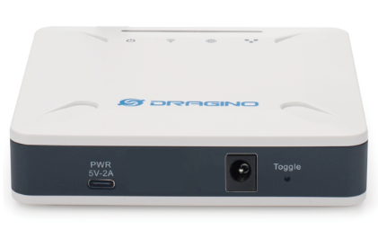
1.1 What is IBPv1 Backup Power Supply & LoRaWAN End Node
The IBPv1 is a reliable backup power supply specifically designed for Dragino Indoor Gateways . It integrates a 6Ah lithium-ion battery and provides a 5V / 2A Type-C output to power the LPS8N series gateways.
With its dedicated mounting bracket , the IBPv1 can be installed neatly together with the LPS8N, making deployment faster and more user-friendly.
Beyond its power backup functionality, the IBPv1 also acts as a LoRaWAN End Node . It can report battery voltage, input power, and output power over a LoRaWAN v1.0.3 network or via the FSK protocol , making it a versatile tool for network operators. It also allows real-time monitoring of local power outages.
1.2 Features
- 6Ah Li-ion battery for reliable backup power
- 5V / 2A Type-C output to support LPS8N and similar devices
- Built-in power monitoring (input, output, battery level)
- Dual transmission support: LoRaWAN v1.0.3 and FSK
- Compact design with bracket for easy installation
1.3 Specification
- Battery Type: 6Ah Li-ion battery
- Recharge Time: ~12 hours
- Backup Duration:
- ~18 hours (LPS8N with 4G connection)
- ~14 hours (LPS8v2 with 4G connection)
- Output: 5V DC / 2A via Type-C port
- Monitoring: Input power, output power, battery voltage
- Wireless Protocols: LoRaWAN v1.0.3 / FSK
1.4 Typical Applications
- Continuous power supply for Dragino LPS8N gateways during power outages
- Backup power for Dragino indoor gateway deployments
- Remote sites where uninterrupted gateway availability is important
- Real-time monitoring of power conditions in LoRaWAN networks
1.5 LED Indicator
IBPv1 has four LED indicators. From left to right, the LEDs are OUT, IN, NET, and SYS.
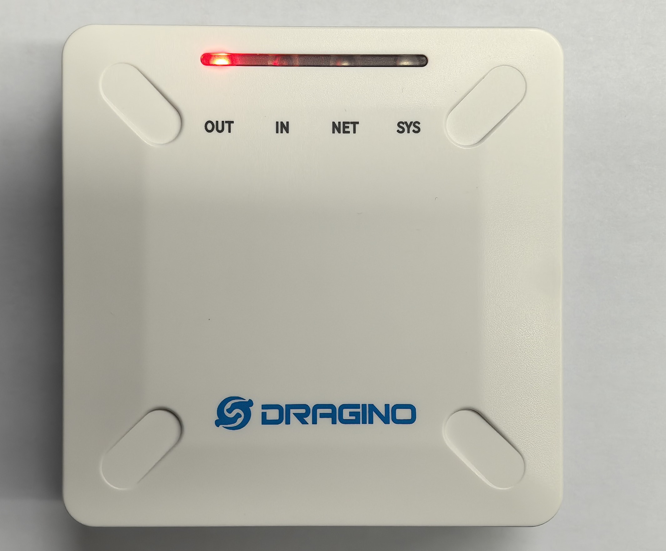
| LED | Function | Behavior |
|---|---|---|
| OUT | 5V output indicator | After IBPv1 joins the LoRaWAN network, after IBPv1 samples the 5V output data and sends an uplink packet, the OUT LED will turn solid red. |
| IN | 12V input indicator | After IBPv1 joins the LoRaWAN network, use an external 12V DC power supply to charge IBPv1. After IBPv1 samples the 12V input data and sends an uplink packet, the IN LED will turn solid red. |
| NET | Network join indicator | Each time IBPv1 joins the LoRaWAN network successfully, the NET LED will turn solid red for 5 seconds. |
| SYS | System indicator | The SYS LED will blink green once each time IBPv1 sends an uplink packet or join request packet. |
For example, after registering IBPv1 in the LoRaWAN server, switch the device to ON. The device will start up and send join request packets. Each time IBPv1 sends a join request packet, the SYS LED will blink green once. After IBPv1 joins the LoRaWAN network successfully, the NET LED will turn solid red for 5 seconds.
1.6 Installation
IBPv1 can be installed together with the LPS8V2 gateway by using the dedicated two-layer metal bracket. The bracket has round locking posts for fixing IBPv1 and the gateway. Both IBPv1 and LPS8V2 have mounting slots on the bottom side. The device can be fixed to the bracket by aligning the round opening of the slot with the round locking post, placing the device down, and then sliding the device forward or backward until it is locked.
1.6.1 Install IBPv1 on the bracket
Place the IBPv1 on the middle layer of the metal bracket.
Align the round openings of the mounting slots on the bottom of IBPv1 with the round locking posts on the bracket.
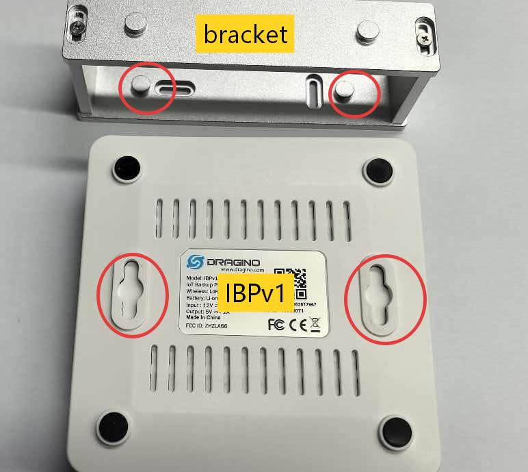
Put the IBPv1 down onto the bracket, and then slide the IBPv1 forward or backward slightly. The mounting slots will lock onto the bracket posts and fix the IBPv1 in place.
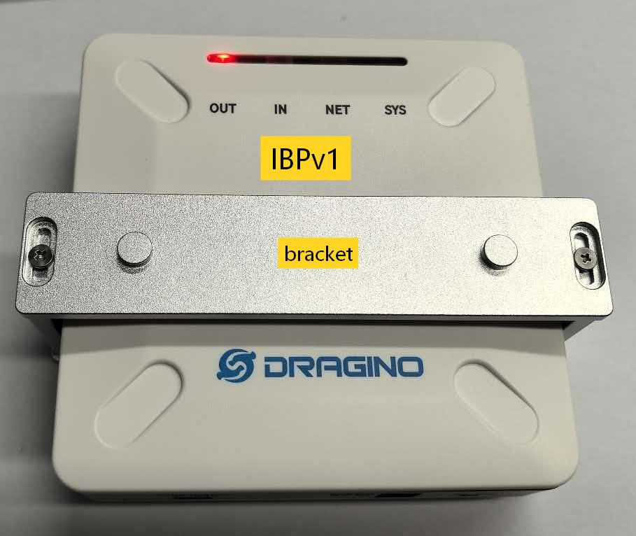
1.6.2 Install a gateway(LPS8N series gateways) on the bracket
Take the LPS8V2 gateway as an example, place the LPS8V2 gateway on the top layer of the metal bracket.
Align the round openings of the mounting slots on the bottom of the LPS8V2 gateway with the round locking posts on the top layer of the bracket.
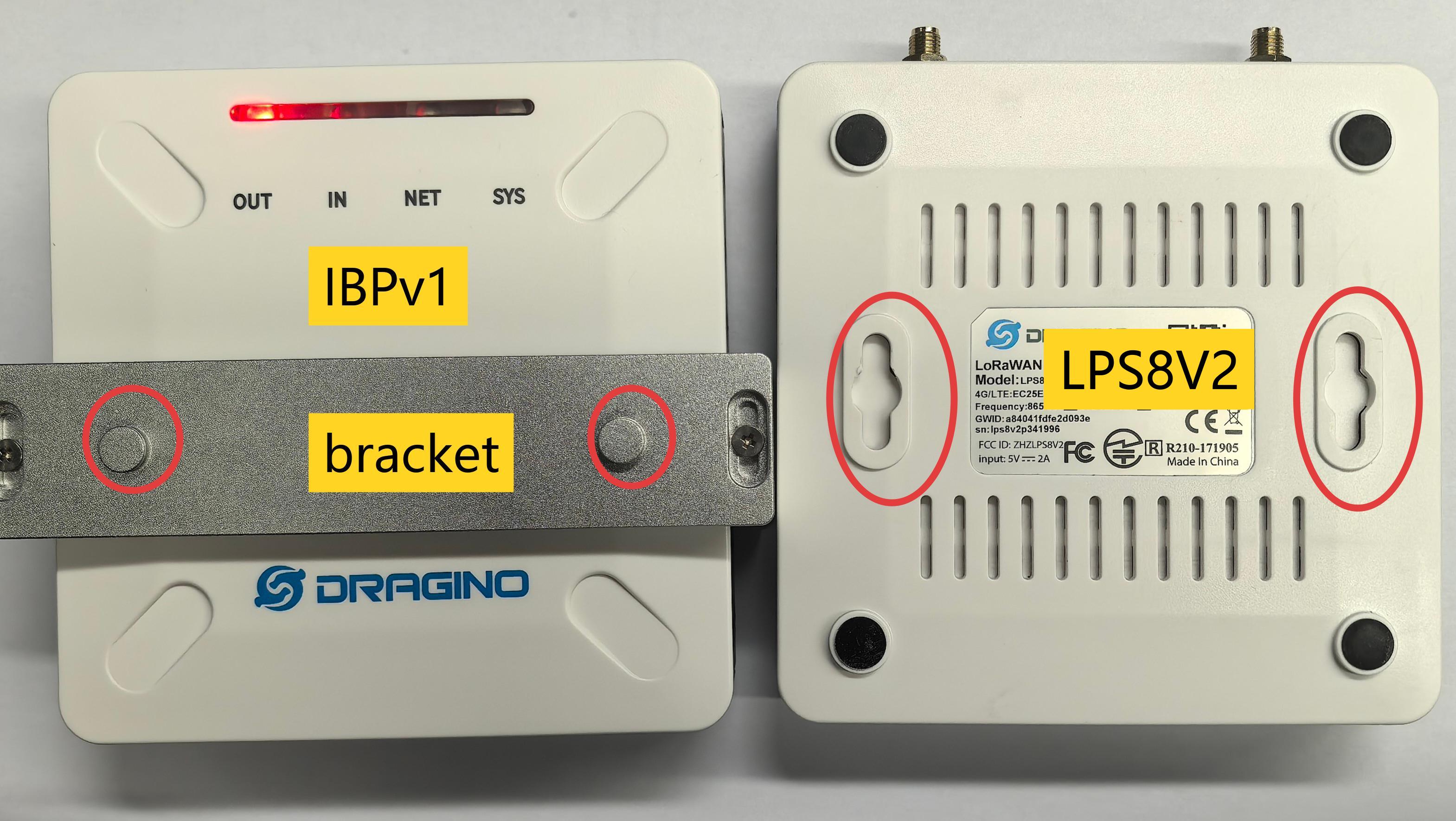
Put the LPS8V2 gateway down onto the bracket, and then slide the gateway forward or backward slightly. The mounting slots will lock onto the bracket posts and fix the LPS8V2 gateway on the top layer.
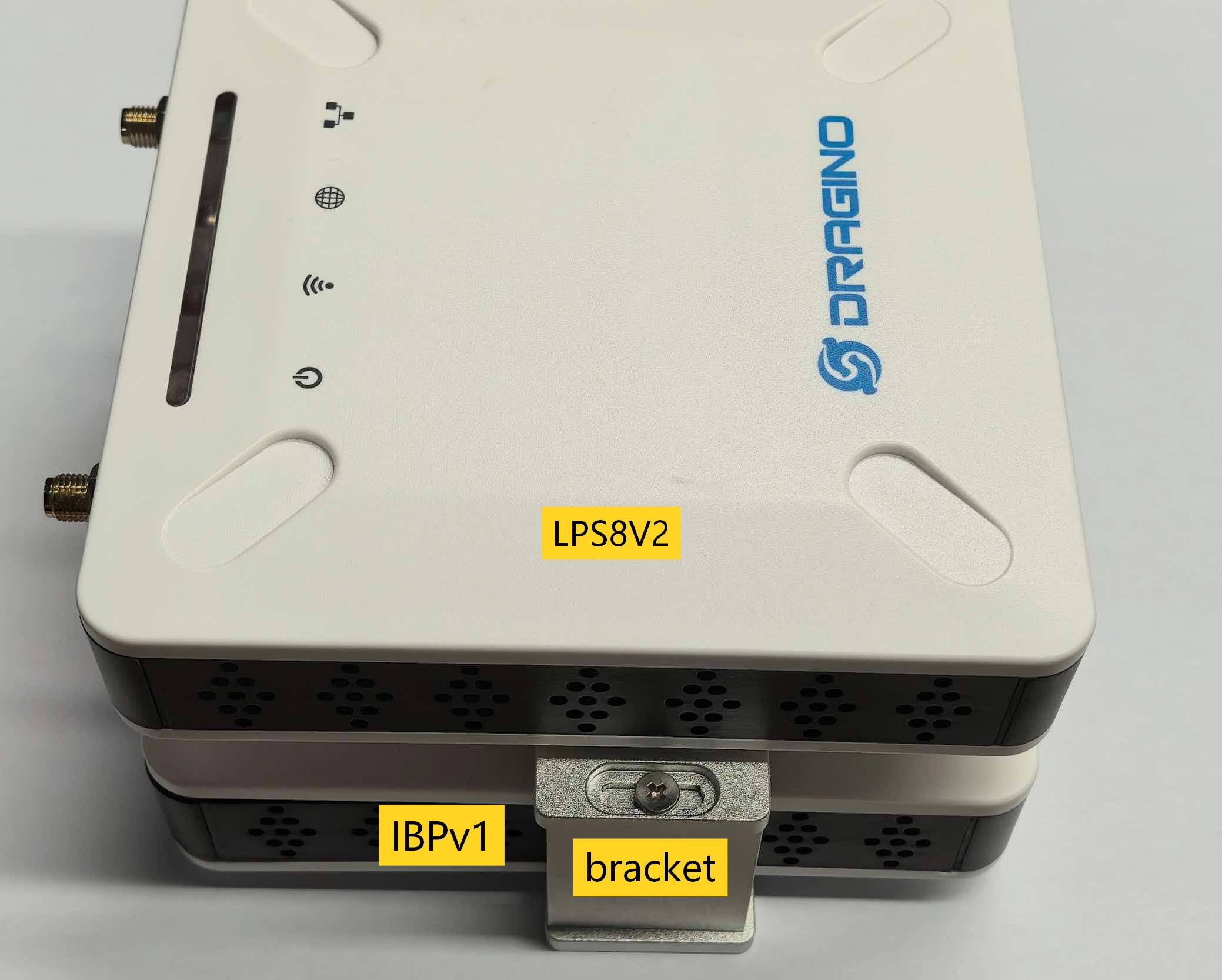
After installation, IBPv1 and the LPS8V2 gateway are fixed together by the bracket. The two devices are separated by the bracket structure, which leaves space between them and helps heat dissipation.
1.6.3 Connect IBPv1 output to LPS8V2 gateway
Use the supplied white Type-C to Type-C adapter cable to connect:
- IBPv1 Out-PWR 5V-2A port
- LPS8V2 gateway PWR 5V-2A port
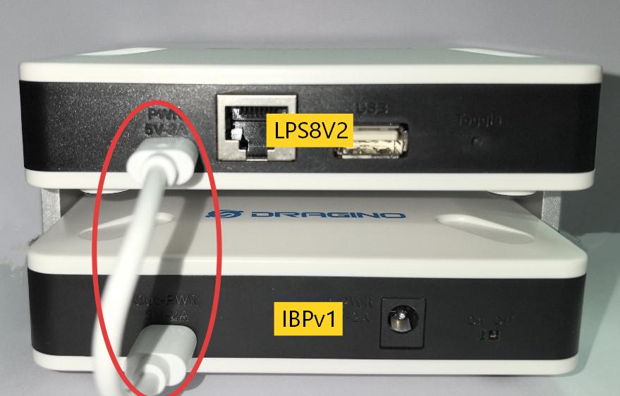
After this connection, IBPv1 can provide 5V power output to the LPS8V2 gateway.
1.6.4 Charge IBPv1
Use a compatible 12V DC power adapter to connect to the IBPv1 In-PWR 12V-2A port.
When the 12V DC input is connected, IBPv1 can charge its built-in battery and provide power backup for the connected gateway.
2. Configure IBPv1 to connect to LoRaWAN network
2.1 How it works
The IBPv1 is configured as LoRaWAN OTAA Class A mode by default. It has OTAA keys to join LoRaWAN network. To connect a local LoRaWAN network, you need to input the OTAA keys in the LoRaWAN IoT server and press the button to activate the IBPv1. It will automatically join the network via OTAA and start to send the sensor value. The default uplink interval is 20 minutes.
2.2 Quick guide to connect to LoRaWAN server (OTAA)
The following network diagram shows how IBPv1 communicates with a LoRaWAN Network Server, for example TTN v3 LoRaWAN Network . We use the LPS8N as a LoRaWAN gateway in this example and ThingsEye as the IoT platform.
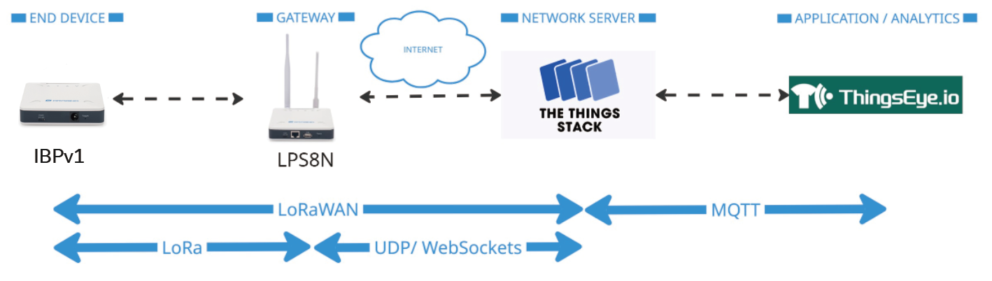
Step 1: Create a device in The Things Stack with the OTAA keys from IBPv1.
Each IBPv1 is shipped with a unique DevEUI, AppEUI, and AppKey. You can find it inside the package of the device. Please keep your registration information in a safe place and don't share with anyone.
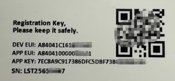
You can enter this key in the LoRaWAN Network Server portal.
The following steps describe how to do it with The Things Stack network server portal. Follow the screenshots for correct configuration:
Create an application.
- On the home screen, click the + Add application button.
- On the Create application page, enter an Application ID to identify your application within The Things Stack and provide an Application name . Read https://thethingsindustries.com/docs/integrations/adding-applications for more information on how to do that.
- Click the Create application button.
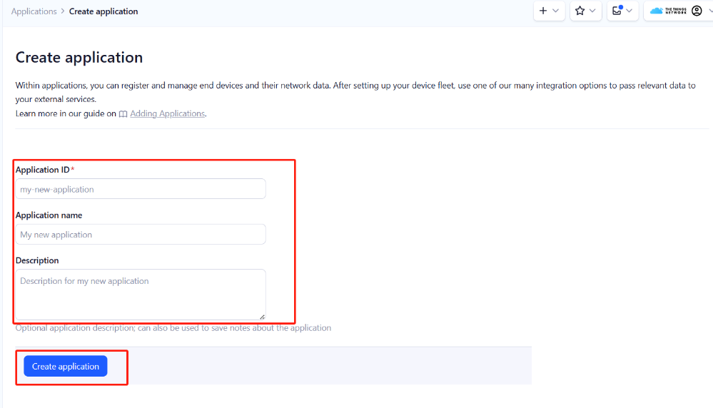
Add devices to the created Application

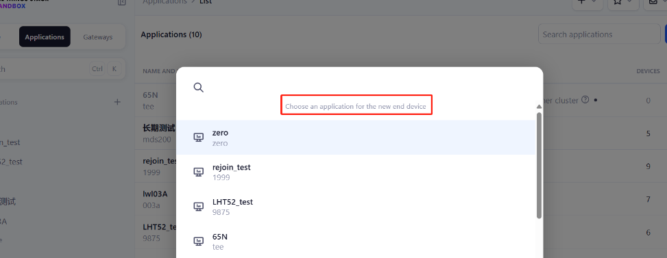
- After creating the application, you will be redirected to the Application overview page.
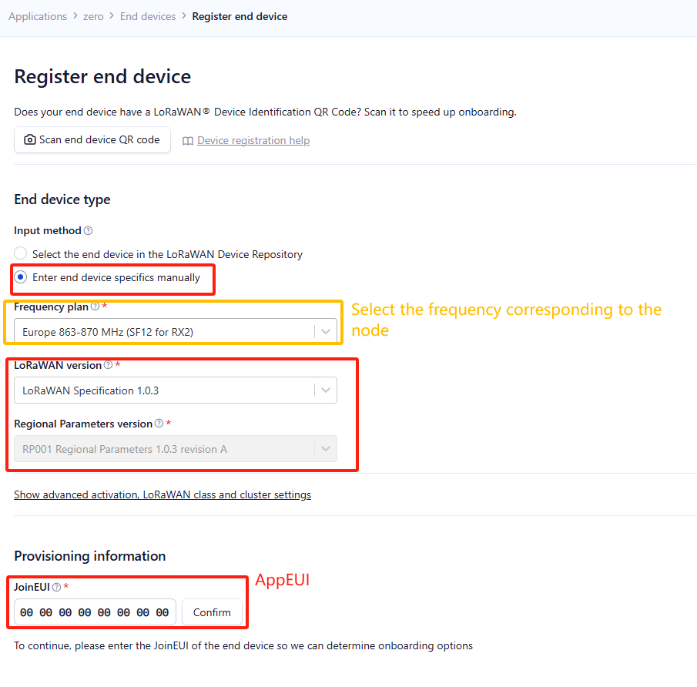
- On the Application overview page, click the + Register end device button.
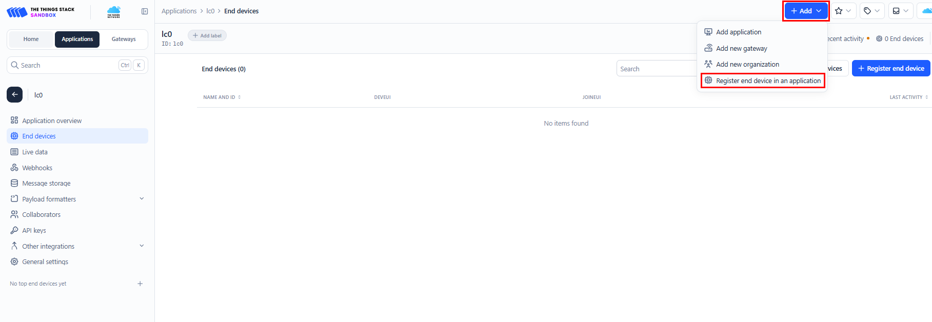
Enter end device specifics manually.
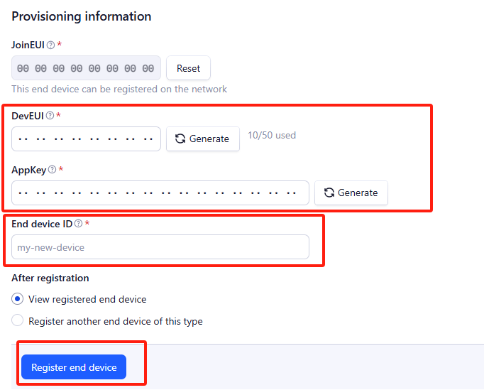
Add DevEUI and AppKey. Customize a platform ID for the device.
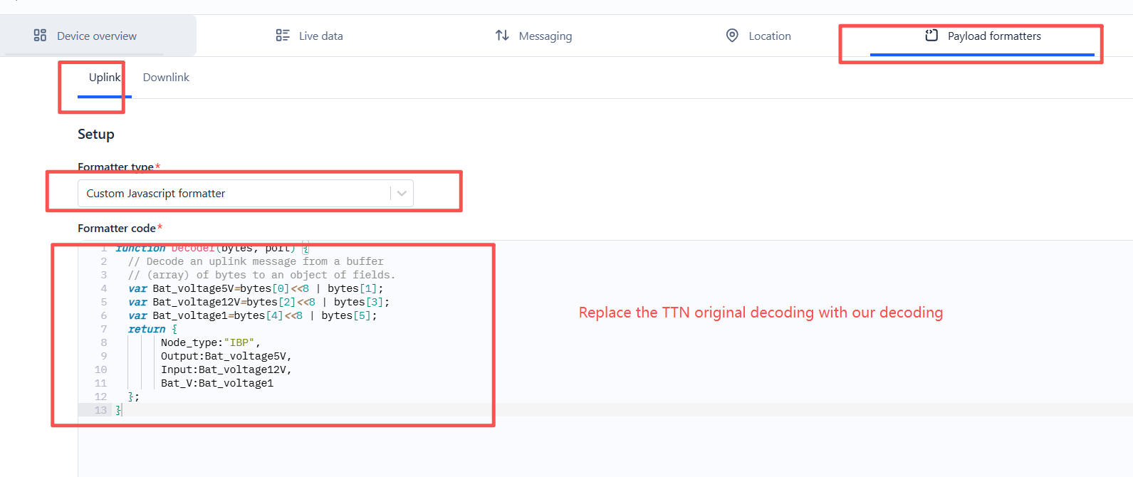
Step 2: Add decoder.
In TTN, user can add a custom payload so it shows friendly reading.
Click this link to get the decoder: https://github.com/dragino/dragino-end-node-decoder/tree/main/
Below is TTN screen shot:
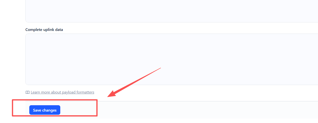
To save the payload formatter, click the ‘Save changes’ button.
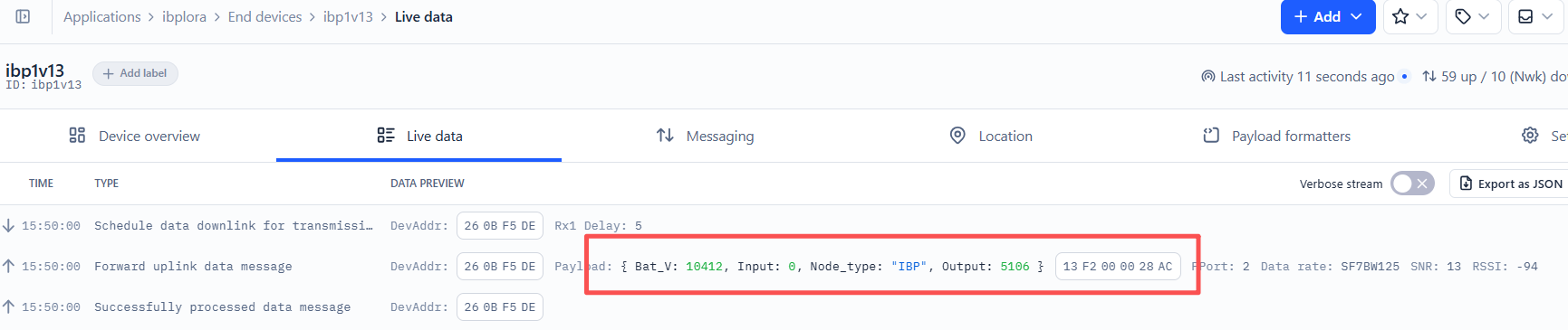
After applying the uplink payload formatter, you can see that all uplink payloads shown in the Live Data section are decoded into fields.
Step 3: Activate on IBPv1
Power on the IBPv1 and let it join the LoRaWAN network. After join success, it will start to upload power status data to the server.
2.3 Uplink Payload (FPort=2)
IBPv1 uploads power status data via FPORT=2.
| Size(bytes) | 2 | 2 | 2 |
|---|---|---|---|
| Value | Output | Input | Bat_V |
| Field | Description | Unit |
|---|---|---|
| Output | 5V output voltage | mV |
| Input | 12V input voltage | mV |
| Bat_V | Battery voltage | mV |
Example:
13 F2 00 00 28 99
Decode:
- Output =
0x13F2= 5106 mV = 5.106V - Input =
0x0000= 0 mV = 0V - Bat_V =
0x2899= 10393 mV = 10.393V
In this example, the IBPv1 5V output is about 5.106V, the 12V input is 0V, and the battery voltage is about 10.393V.
2.4 Frequency Plans
The IBPv1 uses OTAA mode and uses the below frequency plans by default (please visit the link below). Each frequency band uses different firmware. You should update the firmware to the corresponding band for your country.
/docs/LoRaWAN-General-Configuration/frequency-band/
2.5 Firmware Change Log
The firmware can be downloaded from this link: Dropbox--firmware
3. Configure IBPv1
3.1 Configure Methods
IBPv1 supports below configure method:
- LoRaWAN Downlink. Instruction for different platforms: See IoT LoRaWAN Server section.
3.2 General Commands
The general commands are used to configure:
- General system settings like uplink interval.
- LoRaWAN protocol and radio related commands.
These commands are common for all Dragino Devices which support DLWS-005 LoRaWAN Stack. These commands can be found on the wiki:
/docs/LoRaWAN-General-Configuration/at-commands-downlink/
3.3 Set Transmit Interval Time
Feature: Change LoRaWAN End Node Transmit Interval via Downlink Command.
Downlink Command Code: 0x01
Format:The downlink payload consists of the command code (0x01) followed by a 3-byte time value (in seconds).
Example:
| Downlink Payload | Description |
|---|---|
01 00 00 1E | Set Transmit Interval (TDC) = 30 seconds |
01 00 00 3C | Set Transmit Interval (TDC) = 60 seconds |
01 00 01 2C | Set Transmit Interval (TDC) = 300 seconds |
Note: The 3-byte time value is in seconds, ranging from 0 to 16,777,215 (0xFFFFFF). After the end node receives this command, it will apply the new interval.
4. OTA Firmware update
You can update the firmware on IBPv1 to:
- Change the frequency band/region.
- Add new features.
- Fix bugs.
The firmware and changelog can be downloaded from : Firmware download link
Methods to Update Firmware:
- (Recommended way) OTA firmware update via wireless: Firmware OTA Update for LoRaWAN End Node
5. FAQ
This will be added later.
6. Order Info
Part Number: IBPv1-XX
XX : The default frequency band
-
AS923 : LoRaWAN AS923 band
-
AU915 : LoRaWAN AU915 band
-
EU433 : LoRaWAN EU433 band
-
EU868 : LoRaWAN EU868 band
-
KR920 : LoRaWAN KR920 band
-
US915 : LoRaWAN US915 band
-
IN865 : LoRaWAN IN865 band
-
CN470 : LoRaWAN CN470 band
7. Packing Info
Package Includes :
- IBPv1- Backup Power Supply & LoRaWAN End Node x 1
Dimension and weight :
-
Device Size: cm
-
Device Weight: g
-
Package Size / pcs : cm
-
Weight / pcs : g
8. Support
-
Support is provided Monday to Friday, from 09:00 to 18:00 GMT+8. Due to time zone differences, we cannot offer live support. However, your questions will be answered as soon as possible within the mentioned schedule.
-
Please provide as much information as possible regarding your inquiry (e.g., product model, a clear description of the issue, and steps to reproduce it), and send an email to support@dragino.cc .