CO2-LE – LoRaWAN Indoor CO2 Sensor
1. Introduction
1.1 What is CO2-LE LoRaWAN Indoor CO2 Sensor
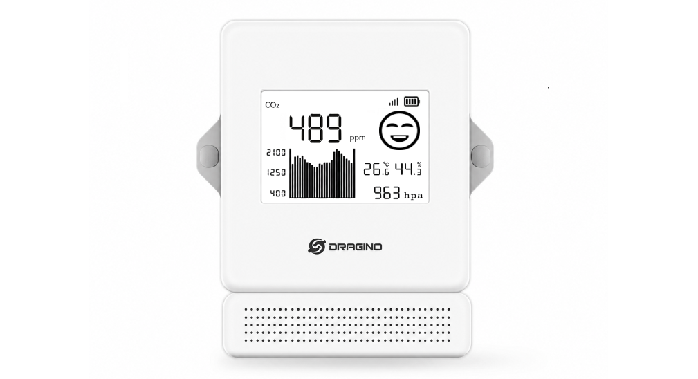
The Dragino CO2-LE is an Indoor LoRaWAN Air Quality Sensor for the Internet of Things solution. It is designed to measure the surrounding environment parameters include: CO2, Temperature , Relative Air Humidity and Air pressure, and then upload to IoT server via LoRaWAN wireless protocol.
CO2-LE is powered by two ER18505 4000mAh battery. The battery can last more than 5 years and is easy to change.
CO2-LE supports BLE configure and wireless OTA update which make user easy to use.
CO2-LE supports CO2 Alarm and Temperature Alarm* features, users can get an alarm for instant notice.
CO2-LE supports Datalog feature, User can retrieve the sensor data from LoRaWAN commands.
Note*: CO2 Alarm and temperature Alarm will decrease a lot the battery life.
1.2 Features
- LoRaWAN 1.0.3 Class A
- Monitor CO2/Temperature/Relative Humidity/Pressure
- Support CO2 alarm
- Support Datalog Feature
- Bands: CN470/EU433/KR920/US915/EU868/AS923/AU915/IN865
- Support Bluetooth v5.4 and LoRaWAN remote configure
- Support wireless OTA update firmware
- Uplink on periodically
- Downlink to change configure
- 8000mAh batteries powered
1.3 Specification
Common DC Characteristics:
- Supply Voltage: built in 8000mAh Li-SOCI2 battery , 2.5v ~ 3.6v
- Operating Temperature: -20 ~ 65°C
CO2 Sensor:
- Sensor: Senseair Sunrise Article No. 006-1-0100
- Target gas: Carbon dioxide(CO2)
- Operating principle: Non-dispersiveinfrared(NDIR)
- Operating range: 0-50°C, 0-85% RH(non-condensing)
- Measurement range: 400ppm to 10000 ppm
- Accuracy: Type ±(50 ppm +3% of reading)
- Pressure Compensation
Temperature Sensor:
- Sensor: sht41
- Range: -40 ~ 125 °C
- Accuracy: ±0.2°C
- Resolution: 0.01°C
Humidity Sensor:
- Sensor: sht41
- Range: 0 ~ 99.9% RH
- Accurancy: ± 1.8%RH
- Resolution: 0.1% RH
Air Pressure:
- Sensor: SPA06-003
- Range: 300~1100hPa
- Accuracy: ± 0.3 hPa (0-65 °C)
- Resolution: 0.06Pa
- Long term stability: ±1.0 hPa/yr
LoRa Spec:
- Frequency Range, Band 1 (HF): 862 ~ 1020 Mhz
- Max +22 dBm constant RF output vs.
- RX sensitivity: down to -139 dBm.
- Excellent blocking immunity
Battery:
- Li/SOCI2 un-chargeable battery
- Capacity: 4000mAh*2
- Self-Discharge: <1% / Year @ 25°C
Power Consumption:
- Sleep Mode: 9uA @ 3.3v
- Each Sampling & Refresh e-Ink: ~13uAh
- LoRa Transmit Mode: 125mA @ 20dBm, 82mA @ 14dBm
1.4 Applications
- Smart Building
- Industrial Monitoring and Control
1.5 Sleep mode and working mode
Deep Sleep Mode: Sensor doesn't have any LoRaWAN activity. This mode is used for storage and shipping to save battery life.
Working Mode: In this mode, Sensor will work as LoRaWAN Sensor to Join LoRaWAN network and send out sensor data to server. Between each sampling/tx/rx periodically, sensor will be in IDLE mode), in IDLE mode, sensor has the same power consumption as Deep Sleep mode.
1.6 BLE connection
CO2-LE supports BLE remote configure.
BLE can be used to configure the parameter of CO2-LE or see the console output from CO2-LE. BLE will be only activate on below case:
- Press button to send an uplink.
- Press button to active CO2-LE.
- Device Power on or reset.
If there is no activity connection on BLE in 60 seconds, CO2-LE will shut down BLE module to enter low power mode.
2. Configure CO2-LE to connect to LoRaWAN network
2.1 How it works
The CO2-LE is configured as LoRaWAN OTAA Class A mode by default. It has OTAA keys to join LoRaWAN network. To connect a local LoRaWAN network, you need to input the OTAA keys in the LoRaWAN IoT server and press the button to activate the CO2-LE. It will automatically join the network via OTAA and start to send the sensor value. The default uplink interval is 20 minutes.
2.2 Quick guide to connect to LoRaWAN server (OTAA)
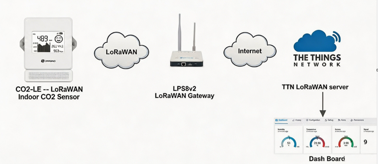
Following is an example for how to join the TTN v3 LoRaWAN Network. Below is the network structure; we use the LPS8v2 as a LoRaWAN gateway in this example.
The LPS8V2 is already set to connected to TTN network , so what we need to now is configure the TTN server.
Step 1: Create a device in TTN with the OTAA keys from CO2-LE.
Each CO2-LE is shipped with a sticker with the default device EUI as below:
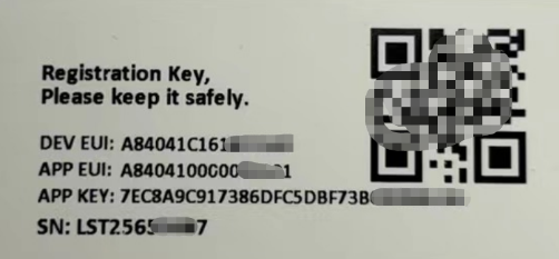
You can enter this key in the LoRaWAN Server portal. Below is TTN screen shot:
Create the application.

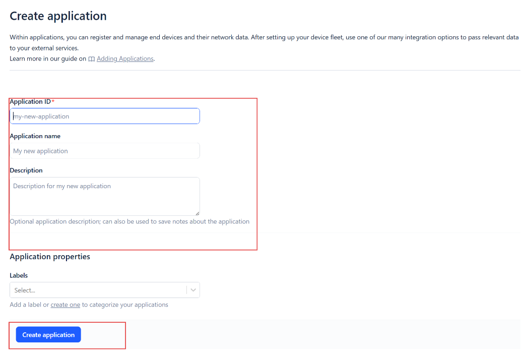
Add devices to the created Application.
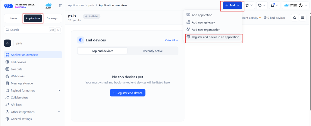
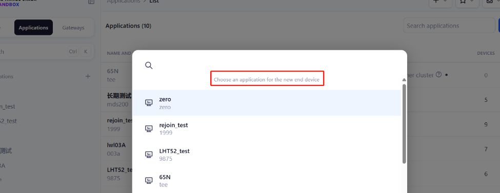
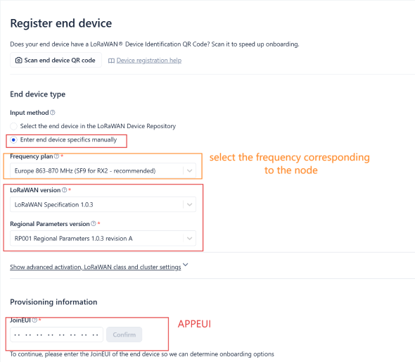
Enter end device specifics manually.
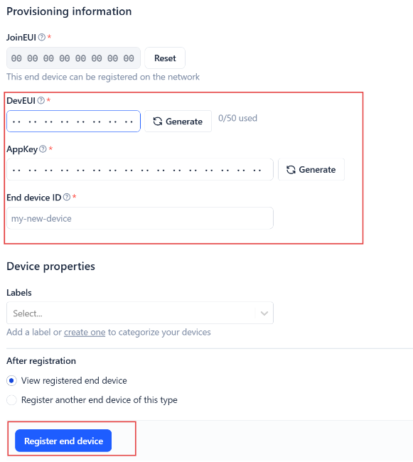
Add DevEUI and AppKey. Customize a platform ID for the device.
Step 2: Add decoder.
In TTN, user can add a custom payload so it shows friendly reading.
Click this link to get the decoder: https://github.com/dragino/dragino-end-node-decoder/tree/main/
Below is TTN screen shot:
Step 3: Activate on CO2-LE
Press the button for 5 seconds to activate the CO2-LE
After join success, it will start to upload messages to TTN and you can see the messages in the panel.
2.3 Calibrate CO2-LE
CO2-LE uses the non-dispersive infrared (NDIR) principle to measure CO2. The device must be calibrated before its first use.
After calibration, all subsequent CO2 measurements use the adjusted calibration parameters. Recalibration is also required after restoring the device to factory settings or replacing the battery, because the original calibration values will be lost.
2.3.1 Button CO2 calibration
The button calibration function is equivalent to AT+CALCMD=3 (Background Calibration). Follow these steps:
- Enter sleep mode. Quickly press the button five times. The device display will show the sleep interface.
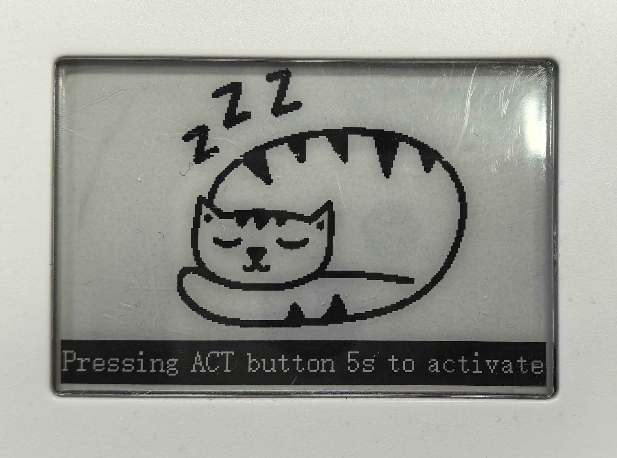
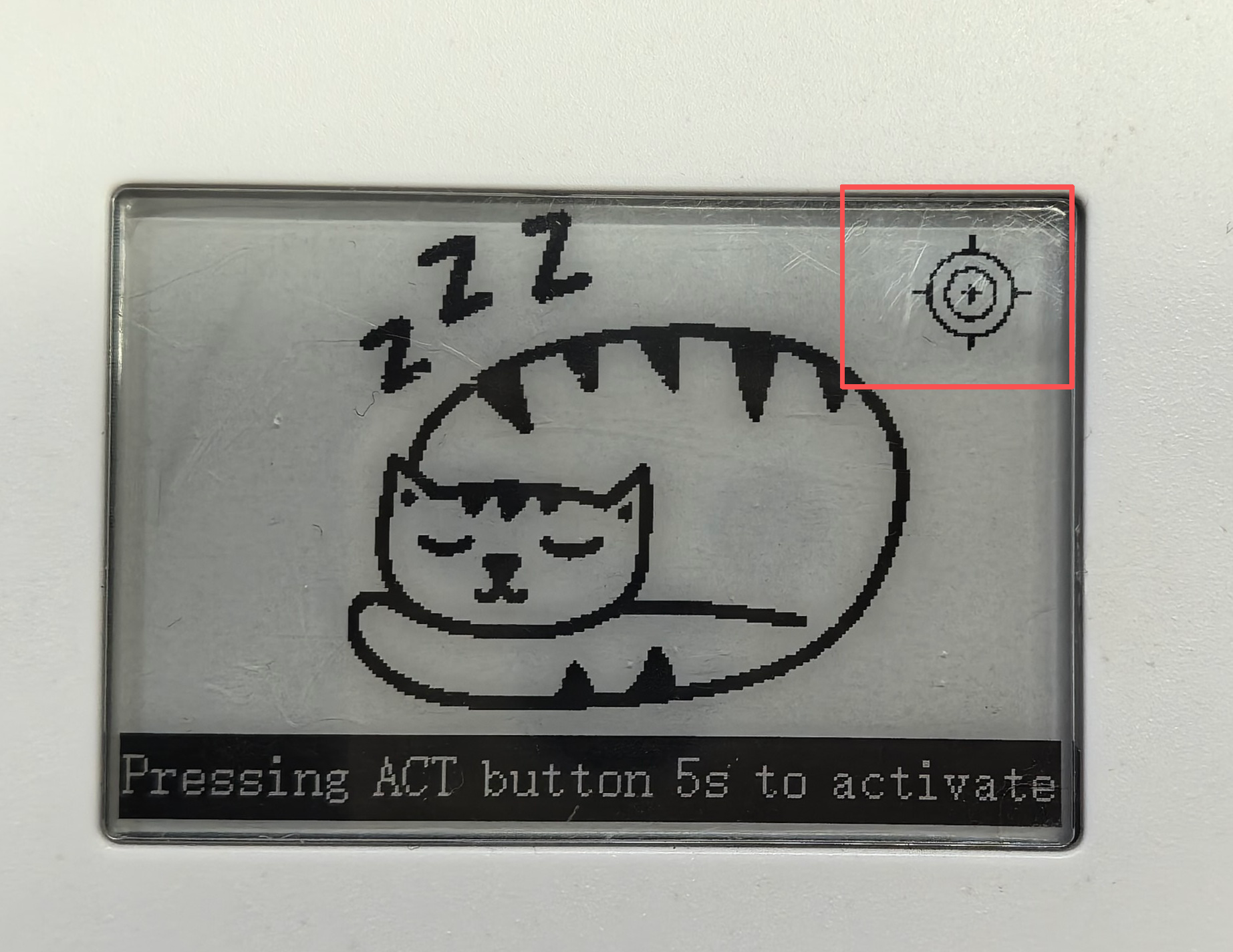
- Prepare a fresh-air environment. Place the device outdoors or in another environment without combustion sources or people. Leave it there for a few minutes, then quickly press the button three times. When calibration is complete, the device will display the calibration-completed interface.
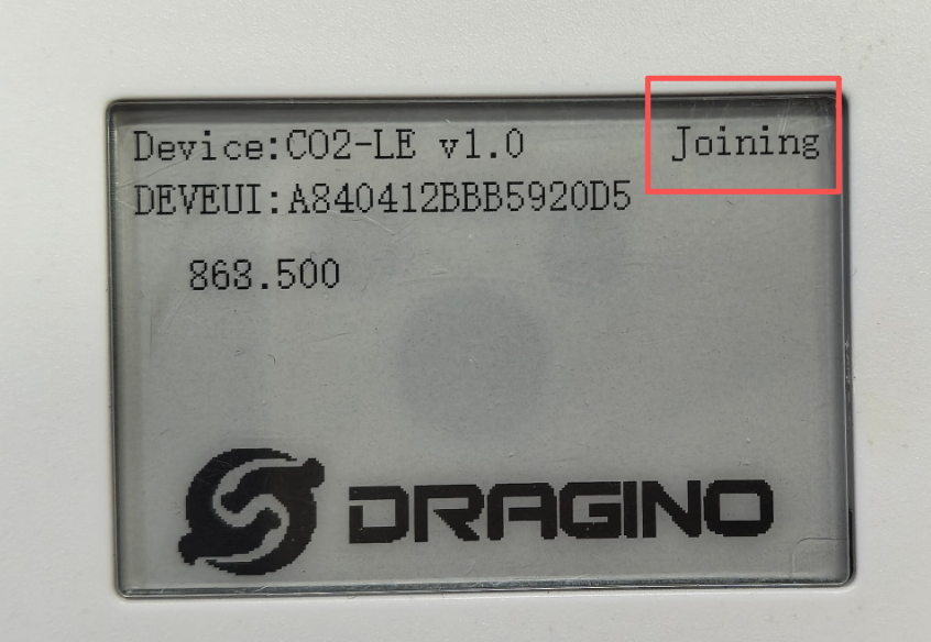
- Reset the device. Press and hold the button until the display shows the Joining interface.
For more calibration methods, please refer to 3.4 Calibration command and 3.5 Calibration mode.
2.4 Uplink Payload
2.4.1 Device Status, FPORT=5
Users can use the downlink command(0x26 01) to ask CO2-LE to send device configure detail, include device configure status. CO2-LE will uplink a payload via FPort=5 to the server.
The Payload format is as below.
| Device Status (FPORT=5) | |||||
|---|---|---|---|---|---|
| Size (bytes) | 1 | 2 | 1 | 1 | 2 |
| Value | Sensor Model | Firmware Version | Frequency Band | Sub-band | BAT |
Example parse in TTNv3

Sensor Model: For CO2-LE, this value is 0x37
Firmware Version: 0x0110, Means: v1.1.0 version
Frequency Band:
0x01: EU868
0x02: US915
0x03: IN865
0x04: AU915
0x05: KZ865
0x06: RU864
0x07: AS923
0x08: AS923-1
0x09: AS923-2
0x0a: AS923-3
0x0b: CN470
0x0c: EU433
0x0d: KR920
0x0e: MA869
Sub-Band:
AU915 and US915:value 0x00 ~ 0x08
CN470: value 0x0B ~ 0x0C
Other Bands: Always 0x00
Battery Info:
Check the battery voltage.
Ex1: 0x0B45 = 2885mV
Ex2: 0x0B49 = 2889mV
2.4.2 Sensor Data. FPORT=2
Sensor Data is uplink via FPORT=2
Size(bytes) | 2 | 2 | 2 | 2 | 2 | 1 |
|---|---|---|---|---|---|---|
| Value | Battery | Temperature | Humidity | Pressure | CO2 | Alarm flag&Other flag |
Alarm flag & Other flag:
| Size(bit) | [bit7:bit6] | bit5 | bit4 | bit3 | bit2 | bit1 | bit0 |
|---|---|---|---|---|---|---|---|
| Value | Reserve | Pressure unit | SHT41_sensor | TEMPL_ flag | TEMPH_ flag | CO2L_ flag | CO2H_ flag |

Battery
Sensor Battery Level.
Ex1: 0x0D32 = 3378mV
Ex2: 0x0B49 = 2889mV
Temperature
If payload is: 0A32H: (0A32 & 8000 == 0), temp = 0A32H /100 = 26.10 degree
If payload is: F876H : (F876 & 8000 == 1) , temp = (F876H - 65536)/100 = -19.30 degrees.
(F876 & 8000: Judge whether the highest bit is 1, when the highest bit is 1, it is negative)
Humidity
Read:0x(018F)=399 Value: 399 / 10=39.9, So 39.9%
PressureExample:
If payload is: 279BH, Pressure = 279BH /10 = 1013.9 hPa
CO2Example:
If payload is: 01FDH, CO2 = 01FDH= 509ppm
Alarm flag
Pressure unit:When the flag is 0, the pressure resolution is 10 Pa; when the flag is 1, the pressure resolution is 1 Pa.
TEMPH_flag: When it is True, the actual temperature exceeds the set alarm temperature.
TEMPL_flag: When it is True, the actual temperature lower than the set alarm temperature.
CO2H_flag: When it is True, the actual CO2 concentration exceeds the set alarm CO2 concentration.
CO2L_flag: When it is True, the actual CO2 concentration lower than the set alarm CO2 concentration.
Example:
AT+TEMPALARM=25,60 ------> temperature: 23.1, TEMPH_flag: "False", TEMPL_flag: "True"
AT+CO2ALARM=400,2000 ------> co2: 2368, CO2H_flag:"True", CO2L_flag:"False"
The display will show:
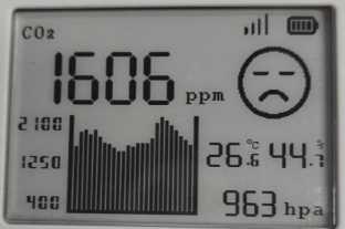
Display content:
The 1606 ppm displayed on the screen represents the carbon dioxide concentration.
The 26.6 °C displayed on the screen represents the current temperature.
The 44.7% displayed on the screen represents humidity.
The 963 hpa displayed on the screen represents air pressure.
The icon in the upper right corner (left side) represents the strength of the RSSI value.
The icon in the upper right corner (right side) displays the battery percentage.
The bar chart on the left shows historical carbon dioxide concentration data for the past 25 groups (excluding the 1606 ppm group).The leftmost bar in a bar chart represents the earliest data, and the rightmost bar represents the latest data.
The emoji icon on the right will change according to the ppm value.
2.5 Payload Decoder file
In TTN, user can add a custom payload so it shows friendly reading
In the page Applications --> Payload Formats --> Custom --> decoder to add the decoder from:
https://github.com/dragino/dragino-end-node-decoder/tree/main
2.6 Datalog Feature
Datalog Feature is to ensure IoT Server can get all sampling data from Sensor even if the LoRaWAN network is down. For each sampling, CO2-LE will store the reading for future retrieving purposes.
2.6.1 How datalog works
CO2-LE will wait for ACK for every uplink, when there is no LoRaWAN network,CO2-LE will mark these records with non-ack messages and store the sensor data, and it will send all messages (10s interval) after the network recovery.
-
a) CO2-LE will do an ACK check for data records sending to make sure every data arrive server.
-
b) CO2-LE will send data in CONFIRMED Mode, but CO2-LE won't re-transmit the packet if it doesn't get ACK, it will just mark it as a NONE-ACK message. In a future uplink if CO2-LE gets a ACK, CO2-LE will consider there is a network connection and resend all NONE-ACK messages.
2.6.2 Enable Datalog
User need to make sure below two settings are enable to use datalog;
- SYNCMOD=1(Default) to enable sync time via LoRaWAN MAC command, click here (AT+SYNCMOD) for detailed instructions.
- PNACKMD=1 to enable datalog feature, click here (AT+PNACKMD) for detailed instructions.
Once CO2-LE Joined LoRaWAN network, it will send the MAC command (DeviceTimeReq) and the server will reply with (DeviceTimeAns) to send the current time to CO2-LE. If CO2-LE fails to get the time from the server, CO2-LE will use the internal time and wait for next time request (AT+SYNCTDC to set the time request period, default is 10 days).
Note: LoRaWAN Server need to support LoRaWAN v1.0.3(MAC v1.0.3) or higher to support this MAC command feature, Chirpstack,TTN V3 v3 and loriot support but TTN V3 v2 doesn't support. If server doesn't support this command, it will through away uplink packet with this command, so user will lose the packet with time request for TTN V3 v2 if SYNCMOD=1.
2.6.3 Unix TimeStamp
CO2-LE uses Unix TimeStamp format based on

User can get this time from link: https://www.epochconverter.com/ :
Below is the converter example
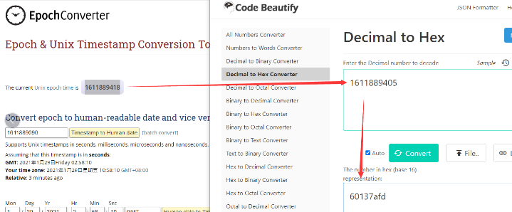
So, we can use AT+TIMESTAMP=1611889405 or downlink 3060137afd00 to set the current time 2021 – Jan -- 29 Friday 03:03:25
2.6.4 Datalog Uplink payload (FPORT=3)
The Datalog uplinks will use below payload format.
Retrieval data payload:
Size(bytes) | 2 | 2 | 2 | 1 | 4 |
|---|---|---|---|---|---|
| Value | CO2 | Humidity | Temperature | Poll message flag | Unix Time Stamp |
Poll message flag :
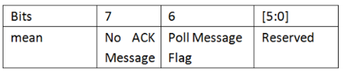
No ACK Message: 1: This message means this payload is fromn Uplink Message which doesn't get ACK from the server before ( for PNACKMD=1 feature)
Poll Message Flag: 1: This message is a poll message reply.
-
Poll Message Flag is set to 1.
-
Each data entry is 11 bytes, to save airtime and battery, devices will send max bytes according to the current DR and Frequency bands.
For example, in US915 band, the max payload for different DR is:
a) DR0: max is 11 bytes so one entry of data
b) DR1: max is 53 bytes so devices will upload 4 entries of data (total 44 bytes)
c) DR2: total payload includes 11 entries of data
d) DR3: total payload includes 22 entries of data.
If devise doesn't have any data in the polling time. Device will uplink 11 bytes of 0
Example:
If CO2-LE has below data inside Flash:
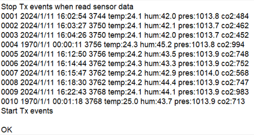
If user sends below downlink command: 3165A010F865A015E405
Where : Start time: 65A010F8 = time 24/1/11 16:02:00
Stop time: 65A015E4 = time 24/1/11 16:23:00
CO2-LE will uplink this payload.
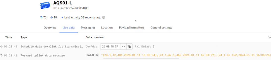
01E401A400F14065A0112E01CE01A500F14065A0114F01C401A400F14065A0118A02EC01B300F24065A0138202F001B100F34065A013F4023801AD00F24065A0143302EB01BC00F24065A014D603D701B900F14065A015D3
Where the first 11 bytes is for the first entry: 01 E4 01 A4 00 F1 40 65 A0 11 2E
- CO2=0x01E4=484 ppm
- Hum=0x01A4/10=42 %
- Temp=0x00F1/10=24.1 ℃
- **poll message flag **=0x40,means reply data,sampling uplink message.
- Unix time is 0x65A0112E=1704888040s=24/1/11 16:02:54
2.7 Frequency Plans
The CO2-LE uses OTAA mode and below frequency plans by default. Each frequency band use different firmware, user update the firmware to the corresponding band for their country.
2.8 Firmware Change Log
Firmware download link:https://www.dropbox.com/scl/fo/o5v6j7qewlks12eso98kl/h?rlkey=v1ian3hmva65924j4h4n0yfz8&dl=0
3. Configure CO2-LE
3.1 Configure Methods
CO2-LE supports below configure method:
- AT Command via Bluetooth Connection (Recommended): BLE Configure Instruction.
- AT Command via UART Connection : See UART Connection.
- LoRaWAN Downlink. Instruction for different platforms: See IoT LoRaWAN Server section.
3.2 General Commands
These commands are to configure:
- General system settings like: uplink interval.
- LoRaWAN protocol & radio related command.
They are same for all Dragino Devices which support DLWS-005 LoRaWAN Stack. These commands can be found on the wiki: AT Commands
3.3 Commands special design for CO2-LE
These commands only valid for CO2-LE, as below:
3.3.1 Set Transmit Interval Time
Feature: Change LoRaWAN End Node Transmit Interval.
AT Command: AT+TDC
| Command Example | Function | Response |
|---|---|---|
| AT+TDC=? | Show current transmit Interval | 30000 |
| AT+TDC=60000 | Set Transmit Interval | OK |
Downlink Command: 0x01
Format: Command Code (0x01) followed by 3 bytes time value.
If the downlink payload=0100003C, it means set the END Node's Transmit Interval to 0x00003C=60(S), while type code is 01.
- Example 1: Downlink Payload: 0100001E // Set Transmit Interval (TDC) = 30 seconds
- Example 2: Downlink Payload: 0100003C // Set Transmit Interval (TDC) = 60 seconds
3.3.2 Get Device Status
Send a LoRaWAN downlink to ask device send Alarm settings.
Downlink Payload: 0x26 01
Sensor will upload Device Status via FPORT=5. See payload section for detail.
3.3.3 Set Temperature Alarm Threshold
-
AT Command:AT+TEMPALARM=min,max (Among them, 100 is an invalid value, which means not set)
-
When min=100, and max≠100, Alarm higher than max
-
When min≠100, and max=100, Alarm lower than min
-
When min≠100 and max≠100, Alarm higher than max or lower than min
Example:
AT+TEMPALARM=100,30 // Alarm when temperature higher than 30.
- Downlink Payload:0x(0C 01 64 1E) // Set AT+TEMPALARM=100,30
(note: 3rd byte= 0x64 for low limit(not set), 4th byte = 0x1E for high limit: 30)
3.3.4 Set CO2 Alarm Threshold
The CO2 alarm function detects CO2 once every minute, so it consumes more power.
-
AT Command:AT+CO2ALARM=min,max (Among them, 0 is an invalid value, which means not set)
-
When min=0, and max≠0, Alarm higher than max
-
When min≠0, and max=0, Alarm lower than min
-
When min≠0 and max≠0, Alarm higher than max or lower than min
Example:
AT+CO2ALARM=400,0 // Alarm when humidity lower than 400.
- Downlink Payload:0x(0C 02 01 90 00 00) // Set AT+CO2ALARM=400,0
(note: 3rd byte+4rd byte= 0x0190 for low limit (400ppm), 5th byte+6rd byte = 0x00 for high limit (not set))
3.3.5 Set Alarm Interval
The shortest time of two Alarm packet. (unit: min)
-
AT Command:AT+ATDC=20 // The shortest interval of two Alarm packets is 20 minutes, Means if there is an alarm packet uplink, there won't be another one in the next 20 minutes.
-
Downlink Payload:0x(0D 14) ---> Set AT+ATDC=0x 14 = 20 minutes
3.3.6 Set Pressure resolution
Set the pressure resolution.
- AT Command:
AT+PRESSACC=1 // The pressure resolution is 10 Pa.
AT+PRESSACC=0 // The pressure resolution is 1 Pa.
- Downlink Payload:
0x(10 01) ---> Set AT+PRESSACC=1
0x(10 00) ---> Set AT+PRESSACC=0
3.3.7 Set Time Sync Mode
Feature: Enable/Disable Sync system time via LoRaWAN MAC Command (DeviceTimeReq), LoRaWAN server must support v1.0.3 protocol to reply to this command.
SYNCMOD is set to 1 by default. If user wants to set a different time from the LoRaWAN server, the user needs to set this to 0.
AT Command:
| Command Example | Function | Response |
|---|---|---|
AT+SYNCMOD=1 | Enable Sync system time via LoRaWAN MAC Command (DeviceTimeReq) The default is zero time zone. | OK |
AT+SYNCMOD=1,8 | Enable Sync system time via LoRaWAN MAC Command (DeviceTimeReq) Set to East eight time zone. | OK |
| AT+SYNCMOD=1,-12 | Enable Sync system time via LoRaWAN MAC Command (DeviceTimeReq) Set to West Twelve Time Zone. | OK |
Downlink Command:
0x28 01 // Same As AT+SYNCMOD=1
0x28 01 08 // Same As AT+SYNCMOD=1,8
0x28 01 F4 // Same As AT+SYNCMOD=1,-12
0x28 00 // Same As AT+SYNCMOD=0
3.3.8 Request the server to send an ACK
AT Command: AT+PNACKMD
| Command Example | Function | Response |
|---|---|---|
| AT+PNACKMD=1 | If the node uploads the ACK as confirm, it will request the server to send an ACK. If the server ack is not received, the node will upload the packets that have not received the ACK the next time it receives the ACK | 1
OK |
| AT+PNACKMD=0 | off request the server to send an ACK | 0 |
Downlink Command: 0x34
0X34 01 // Same As AT+PNACKMD=1
0x34 00 // Same As AT+PNACKMD=0
3.4 Calibration command
Note: If the device is not calibrated for the first time, there will be a certain degree of drift.After the FDR is restored to factory settings or the device battery is replaced, the original calibration values will be lost and recalibration will be required.
After having performed the calibration,all following measurements will use the adjusted calibration parameters.
3.4.1 Restore factory Calibration (AT+CALCMD=0)
Restores calibration parameters factory calibration values.
Downlink Payload: 0x0F 00
3.4.2 Forced ABC Calibration (AT+CALCMD=1)
Sensor will perform an ABC calibration after receiving this command if sensor has valid ABC data.The command can be used if one for some reason wants to do an ABC adjustment before one ABC period has passed(when a normal ABC calibration is done).
Downlink Payload: 0x0F 01
3.4.3 Target Calibration (AT+CALCMD=2 Equivalent to AT+CALCMD=2,400)
Target concentration calibration assumes that sensor is put into a target environment with a known CO2 concentration. Such as outdoor fresh air 400ppm.
Downlink Payload:
- 0x0F 02 ==> AT+CALCMD=2
- 0x0F 02 01 90 ==> AT+CALCMD=2,400
- 0x0F 02 01 F4 ==> AT+CALCMD=2,500
3.4.4 Background Calibration (AT+CALCMD=3)
A “fresh air” baseline environment is by default 400 ppm at normal ambient atmospheric pressure by sea level. It can be referenced in a crude way by placing the sensor in direct proximity to outdoor air, free of combustion sources and human presence, preferably during either by open window or fresh air inlets or similar. Calibration gas by exactly 400ppm can be purchased and used. Background calibration and ABC calibration share the same target value (fresh air = 400ppm).
Downlink Payload: 0x0F 03
3.4.5 Zero Calibration (AT+CALCMD=4)
Zero-calibrations are the most accurate recalibration routine. A zero-ppm environment is most easily created by flushing the optical cell of the sensor module and filling up an encapsulating enclosure with nitrogen gas, N2, displacing all previous air volume concentrations. Another less reliable or accurate zero reference point can be created by scrubbing an airflow using e.g. Soda lime.
Downlink Payload: 0x0F 04
3.5 calibration mode
3.5.1 Enabled ABC Calibration (AT+CALMOD=1, default)
The Automatic Baseline Correction algorithm is a proprietary Senseair method for referencing to “fresh air” as the lowest, but required stable, CO2-equivalent internal signal the sensor has measured during a set time period. This time period by default is 180hrs as to catch low-occupancy and other lower-emission time periods and favourable outdoor wind-directions and similar which can plausibly and routinely expose the sensor to the most true fresh air environment. If such an environment can never be expected to occur, either by sensor locality or ever-presence of CO2 emission sources, or exposure to even lower concentrations than the natural fresh air baseline, then ABC recalibration can’t be used. In each new measurement period, the sensor will compare it to the stored one at the ABC parameters registers, and if new values show a lower CO2-equivalent raw signal while also in a stable environment, the reference is updated with these new values. The ABC algorithm also has a limit on how much it is allowed to change the baseline correction offset with, per each ABC cycle, meaning that self-calibrating to adjust to bigger drifts or signal changes may take more than one ABC cycle.
Downlink Payload: 0x0E 01
3.5.2 Disabled ABC Calibration (AT+CALMOD=0)
If the device is in a greenhouse or enclosed environment, it is recommended to turn off ABC calibration. And use Target Calibration for calibration.
Downlink Payload: 0x0E 00
3.5.3 Button CO2 calibration function (Equivalent to AT+CALCMD=3)
The first step is to put your device into sleep mode. Press the button five times quickly and the device will light up solid red for 5 seconds.
In the second step, take the device outside to an environment without combustion sources and people, let it sit for a few minutes, and then press the button three times quickly. The calibration is complete after the blue light stays on for 5 seconds.
The last step is to reset the device, press and hold the button until the green light flashes.
3.6 Display screen control
Feature: Enable or disable the sensor data display on the screen.
AT Command: AT+DISPLAY
AT+DISPLAY : Get or set the display screen off or on.
| Command Example | Function |
|---|---|
| AT+DISPLAY=? | Get the current display setting. |
| AT+DISPLAY=0 | Enable the sensor data display (default). |
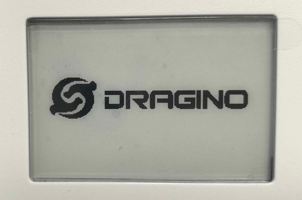
| AT+DISPLAY=1 | Disable the sensor data display. Show only the Dragino logo. |
When AT+DISPLAY=0, the screen updates and displays the latest sensor data after the device joins the network and sends an uplink packet.

When AT+DISPLAY=1, the screen shows only the Dragino logo.
Downlink Command: 0x1F
- Example: 0x1F00 // Same as AT+DISPLAY=0
- Example: 0x1F01 // Same as AT+DISPLAY=1
3.7 Temperature display mode
Feature: Set the temperature unit displayed on the screen.
AT Command: AT+TEMPMODE
AT+TEMPMODE : Get or set the temperature display mode.
| Command Example | Function |
|---|---|
| AT+TEMPMODE=? | Get the current temperature display mode. |
| AT+TEMPMODE=0 | Display the latest temperature reading in Celsius (°C). |
| AT+TEMPMODE=1 | Display the latest temperature reading in Fahrenheit (°F). |
Downlink Command: 0x08
- Example: 0x0800 // Same as AT+TEMPMODE=0
- Example: 0x0801 // Same as AT+TEMPMODE=1
4. Meaning of E-Ink screen icons
Device mode icons
| Mode | Screen icon |
|---|---|
| Deep Sleep Mode | 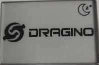 |
| Joining LoRaWAN network Mode | 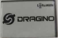 |
| CO2 calibration completed | 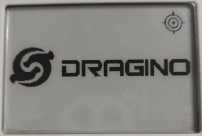 |
Emoji
| CO2 range | Emoji icon |
|---|---|
| 400-600ppm |  |
| 601-1000ppm |  |
| 1001-1500ppm |  |
| >1500ppm |  |
Signal strength
| Signal strength | Signal icon |
|---|---|
| RSSI greater than -55 |  |
| RSSI greater than -75 and less than or equal to -55 |  |
| RSSI greater than -90 and less than or equal to -75 |  |
| RSSI value less than or equal to -90 |  |
Battery percentage
| Battery percentage | Battery icon |
|---|---|
| Greater than 75% and less than or equal to 100% |  |
| Greater than 50% and less than or equal to 75% |  |
| Greater than 25% and less than or equal to 50% |  |
| Less than or equal to 25% |  |
5. Battery & Power Consumption
5.1 Battery Life
In a normal 20 minutes uplink situation , the battery life can last from 2 ~ 8 years depends on signal environment. The Alarm feature will reduce the battery life a lot .
See below link for detail information about the battery life calculation.
Battery Info & Power Consumption Analyze .
5.2 Replace Battery
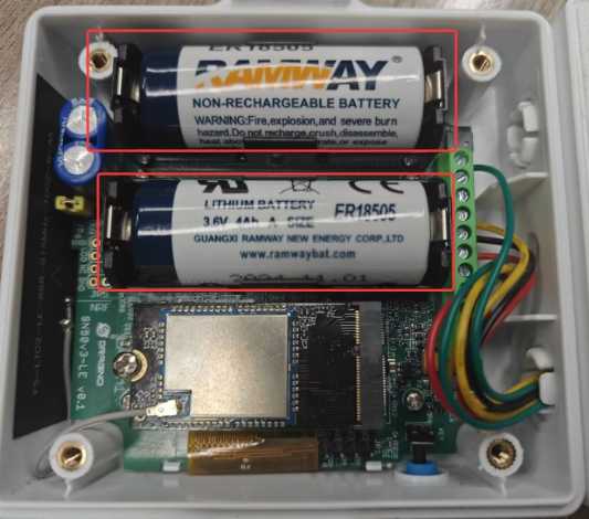
CO2-LE uses an ER18505 battery. If the battery is running out, User can purchase an ER18505 battery and replace. Make sure don't mess the + & - position.
6. OTA Firmware update
User can change firmware CO2-LE to:
- Change Frequency band/ region.
- Update with new features.
- Fix bugs.
Firmware and changelog can be downloaded from : Firmware download link
Methods to Update Firmware:
- (Recommanded way) OTA firmware update via wireless : LoRawan OTA Firmware
- Update through UART TTL interface : Instruction.
7. FAQ
7.1 Do i need to calibrate the CO2 reading of CO2-LE?
CO2-LE uses the non-dispersive infrared (NDIR) principle to measure CO2. The device must be calibrated before its first use. For detailed calibration procedures, see Calibrate CO2-LE.
8. Order Info
Part Number: CO2-LE-XX
XX: The default frequency band
-
AS923: LoRaWAN AS923 band
-
AU915: LoRaWAN AU915 band
-
EU433: LoRaWAN EU433 band
-
EU868: LoRaWAN EU868 band
-
KR920: LoRaWAN KR920 band
-
US915: LoRaWAN US915 band
-
IN865: LoRaWAN IN865 band
-
CN470: LoRaWAN CN470 band
9. Packing Info
Package Includes:
- CO2-LE LoRaWAN Indoor CO2 Sensor
Dimension and weight:
-
Package Size / pcs : 160 x 110 x 40 mm
-
Weight / pcs : 300 g
10. Support
-
Support is provided Monday to Friday, from 09:00 to 18:00 GMT+8. Due to different timezones we cannot offer live support. However, your questions will be answered as soon as possible in the before-mentioned schedule.
-
Provide as much information as possible regarding your enquiry (product models, accurately describe your problem and steps to replicate it etc) and send a mail to Support@dragino.cc.