PS-KN
PS-KN – NB-IoT Analog Sensor
1. Introduction
1.1 What is NB-IoT Analog Sensor
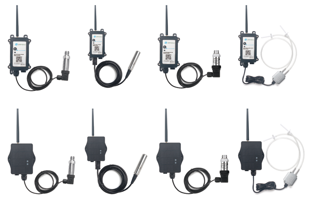
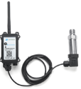
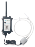
The Dragino PS-KN is a NB-IoT Analog Sensor for Internet of Things solution. PS-KN has 5v and 12v output, 420mA, 030v input interface to power and get value from Analog Sensor. PS-KN will convert the Analog Value to NB-IoT wireless data and send to IoT platform via NB-IoT network.
PS-KN supports different uplink methods including MQTT, MQTTs, UDP ,TCP&CoAP for different application requirement, and support uplinks to various IoT Servers.
PS-KN supports BLE configure and OTA update which make user easy to use.
PS-KN is powered by DC Power + 1000mAh BackUp Battery, it is designed for long-term use up to several years.
PS-KN has optional built-in SIM card and default IoT server connection version. Which makes it works with simple configuration.
1.2 Features
- NB-IoT Bands: B1/B2/B3/B4/B5/B7/B8/B20/B28/B34/B27/B28/B38/B39/B40/B41/B66
- Ultra-low power consumption
- 1 x 0
20mA input , 1 x 030v input - 5v and 12v output to power external sensor
- Multiply Sampling and one uplink
- Support Bluetooth v5.1 remote configure and update firmware
- Uplink on periodically
- Downlink to change configure
- Solar panel + 3000mAh Li-ion Battery (PS-KS)
- Charging Pad + 1000mAh Li-ion Battery (PS-KN)
- IP66 Waterproof Enclosure
- Uplink via MQTT, MQTTs, TCP, or UDP
- Nano SIM card slot for NB-IoT SIM
1.3 Specification
Common DC Characteristics:
- Supply Voltage: 2.5v ~ 3.6v
- Operating Temperature: -40 ~ 85°C
Current Input (DC) Measuring :
- Range: 0 ~ 20mA
- Accuracy: 0.02mA
- Resolution: 0.001mA
Voltage Input Measuring:
- Range: 0 ~ 30v
- Accuracy: 0.02v
- Resolution: 0.001v
NB-IoT Spec:
NB-IoT Module: EG800-NGFF
Support Bands:
EU:
For European, Asia, Austrial, LTE-FDD: B1/3/5/7/8/20/28
-
B1 @FDD: 2100MHz
-
B3 @FDD: 1800MHz
-
B5 @FDD: 850MHz
-
B7 @FDD: 2600MHz
-
B8 @FDD: 900MHz
-
B20 @FDD: 800MHz
-
B28 @FDD: 700MHz
LA:
For Latin America, LTE-FDD: B2/3/4/5/7/8/28/66
-
B2 @FDD: 1900MHz
-
B3 @FDD: 1800MHz
-
B4 @FDD: 1700/2100MHz
-
B5 @FDD: 850MHz
-
B7 @FDD: 2600MHz
-
B8 @FDD: 900MHz
-
B28 @FDD: 700MHz
-
B66 @FDD: 1700/2100MHz
NA:
For North America, LTE-FDD: B2/4/5/12/13/66
-
B2 @FDD: 1900MHz
-
B4 @FDD: 1700/2100MHz
-
B5 @FDD: 850MHz
-
B12 @H-FDD: 720MHz
-
B13 @H-FDD: 740MHz
-
B66 @FDD: 1700/2100MHz
Battery:
- Li-ion Battery
- Capacity: 3000mAh & 1000mAh
- Self Discharge: <1% / Year @ 25°C
- Max continuously current: 130mA
- Max boost current: 2A, 1 second
Power Consumption
- STOP Mode: 10uA @ 3.3v
- Max transmit power: 350mA@3.3v
1.4 Probe Types
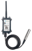
1.4.1 Thread Installation Type
- Hersman Pressure Transmitter
- Measuring Range: -0.1 ~ 0 ~ 60MPa, see order info.
- Accuracy: 0.2% F.S
- Long-Term Stability: 0.2% F.S ±0.05%
- Overload 200% F.S
- Zero Temperature Drift: 0.03% FS/℃(≤100Kpa), 0.02%FS/℃(>100Kpa)
- FS Temperature Drift: 0.003% FS/℃(≤100Kpa), 0.002%FS/℃(>100Kpa)
- Storage temperature: -30℃~80℃
- Operating temperature: -20℃~60℃
- Connector Type: Various Types, see order info
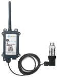
1.4.2 Immersion Type
- Immersion Type, Probe IP Level: IP68
- Measuring Range: Measure range can be customized, up to 100m.
- Accuracy: 0.2% F.S
- Long-Term Stability: ±0.2% F.S / Year
- Storage temperature: -30℃~80℃
- Operating temperature: 0℃~50℃
- Material: 316 stainless steels
1.4.3 Food Safety Thread Type
- Material: Food Grade 316L Stainless Steel, Anti-clogging, Pressure and wear resistant
- Application Scenarios: Measuring viscous media: food and beverages, viscous gels, pigments and paints, pulp and cement, pump trucks, concrete, particulate matter
- Measuring Range: -100Kpa ~ 0 ~ 100MPa
- Compensation Temperature: 10 ~ 70°C
- Output Signal: 4 ~ 20mA
- Power Supply: 24V DC
- Ambient Temperature: -40 ~ 85°C
- Enclosure Protection: IP65
- Pressure Type: Gauge pressure, Absolute pressure, Sealed pressure
- Zero-point Temperature Drift: +0.03%FS/°C
- Sensitivity Temperature Drift: +0.03%FS/°C
- Overload Pressure: 200%FS
- Long-term Stability: ≤0.2%FS/°C
- Natural Frequency: 5HZ ~ 650HZ
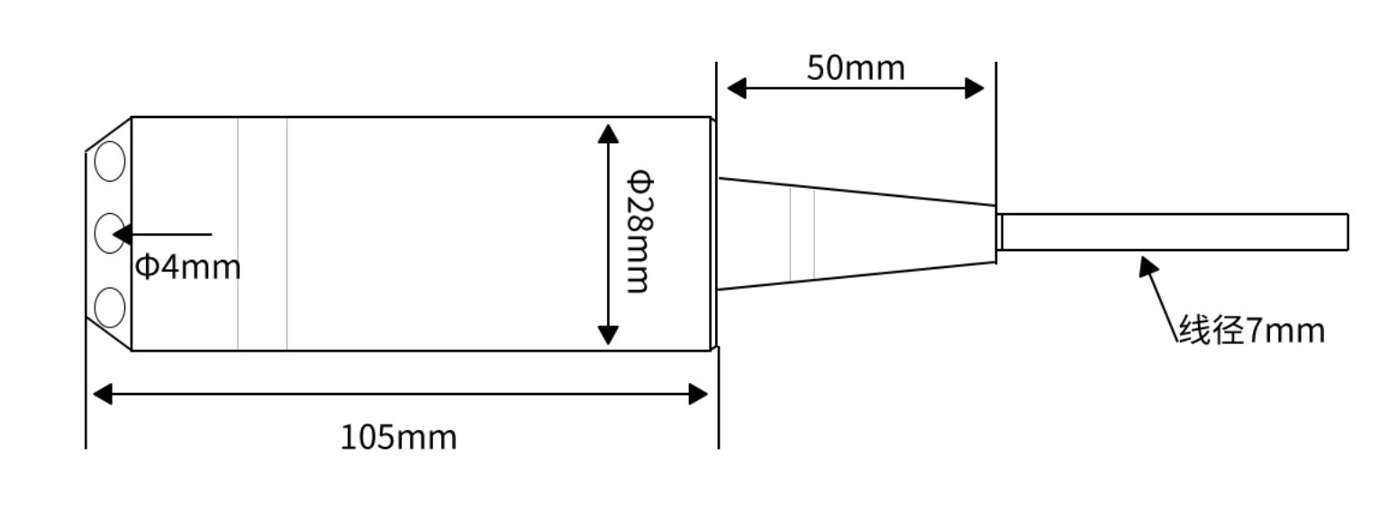
1.4.4 Wireless Differential Air Pressure Sensor
- easuring Range: -100Pa ~ 100KPa(Optional measuring range).
- Accuracy: 0.5% F.S, resolution is 0.05%.
- Overload: 300% F.S
- Zero temperature drift: ±0.03%F.S/°C
- Operating temperature: -20°C~60°C
- Storage temperature: -20°C~60°C
- Compensation temperature: 0~50°C
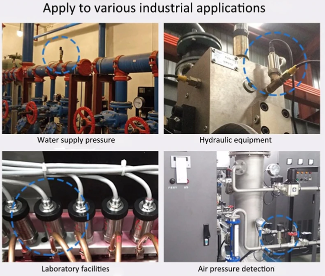
1.5 Application and Installation
1.5.1 Thread Installation Type
Application:
- Hydraulic Pressure
- Petrochemical Industry
- Health and Medical
- Food & Beverage Processing
- Auto-controlling house
- Constant Pressure Water Supply
- Liquid Pressure measuring
Order the suitable thread size and install to measure the air / liquid pressure
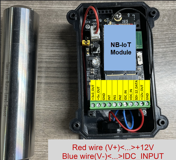
1.5.2 Immersion Type
Application:
Liquid & Water Pressure / Level detect.

The Immersion Type pressure sensor is shipped with the probe and device separately. When user got the device, below is the wiring to for connect the probe to the device.
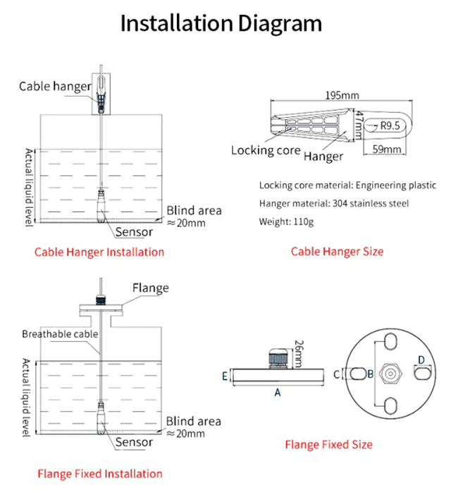
Size of immersion type water depth sensor:
1.5.3 Food Safety Thread Type
Application:
- Milk Oil Storage Tank Monitoring
- Pigment And Paint Storage Monitoring
- Pulp & Cement Storage
- Concrete Pump Truck

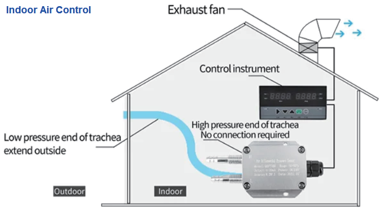
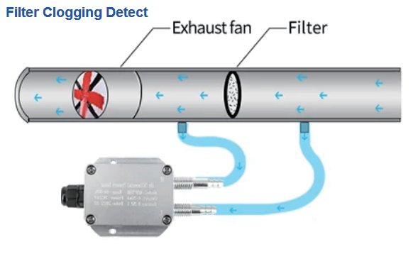
1.5.4 Wireless Differential Air Pressure Sensor
Application:
Indoor Air Control & Filter clogging Detect.
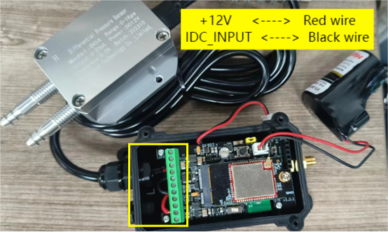
Below is the wiring to for connect the probe to the device.
Size of wind pressure transmitter:
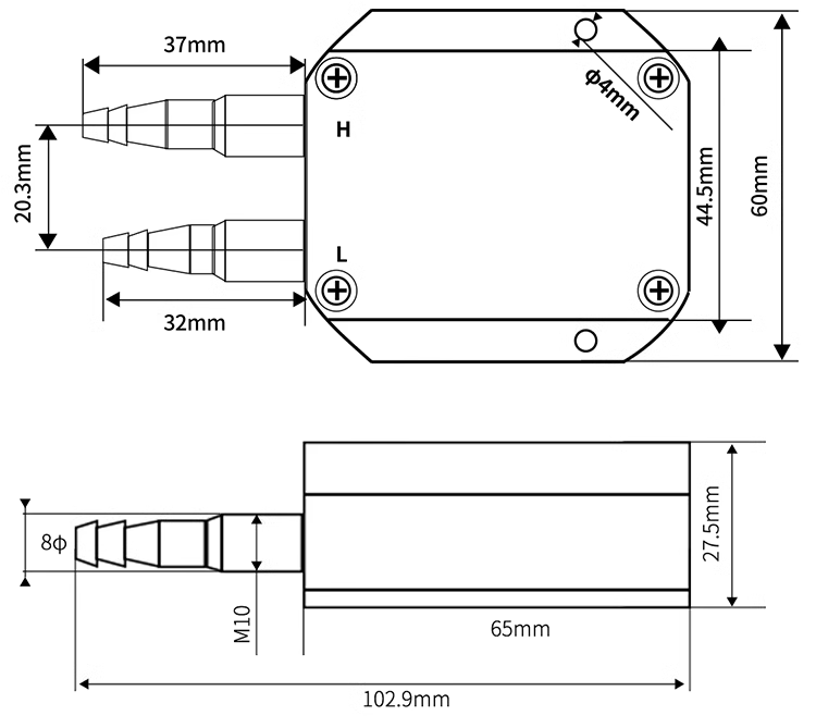
Note: The above dimensions are measured by hand, and the numerical error of the shell is within ±0.2mm.
1.6 Sleep mode and working mode
Deep Sleep Mode: Sensor doesn't have any NB-IoT activate. This mode is used for storage and shipping to save battery life.
Working Mode: In this mode, Sensor will work as NB-IoT Sensor to Join NB-IoT network and send out sensor data to server. Between each sampling/tx/rx periodically, sensor will be in IDLE mode), in IDLE mode, sensor has the same power consumption as Deep Sleep mode.
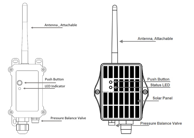
1.7 Button & LEDs
| Behavior on ACT | Function | Action |
|---|---|---|
| Send an uplink | If sensor has already attached to CAT-1 network, sensor will send an uplink packet, blue led will blink once. Meanwhile, BLE module will be active and user can connect via BLE to configure device. | |
| Active Device | Green led will fast blink 5 times, device will enter OTA mode for 12 seconds. And then start to attach CAT-1 network. Once sensor is active, BLE module will be active and user can connect via BLE to configure device, no matter if device attach CAT-1 network or not. | |
| Deactivate Device | Red led will solid on for 5 seconds. Means device is in Deep Sleep Mode. |
Note: When the device is executing a program, the buttons may become invalid. It is best to press the buttons after the device has completed the program execution.
1.8 BLE connection
PS-KN support BLE remote configure and firmware update.
BLE can be used to configure the parameter of sensor or see the console output from sensor. BLE will be only activate on below case:
- Press button to send an uplink
- Press button to active device.
- Device Power on or reset.
If there is no activity connection on BLE in 60 seconds, sensor will shut down BLE module to enter low power mode.
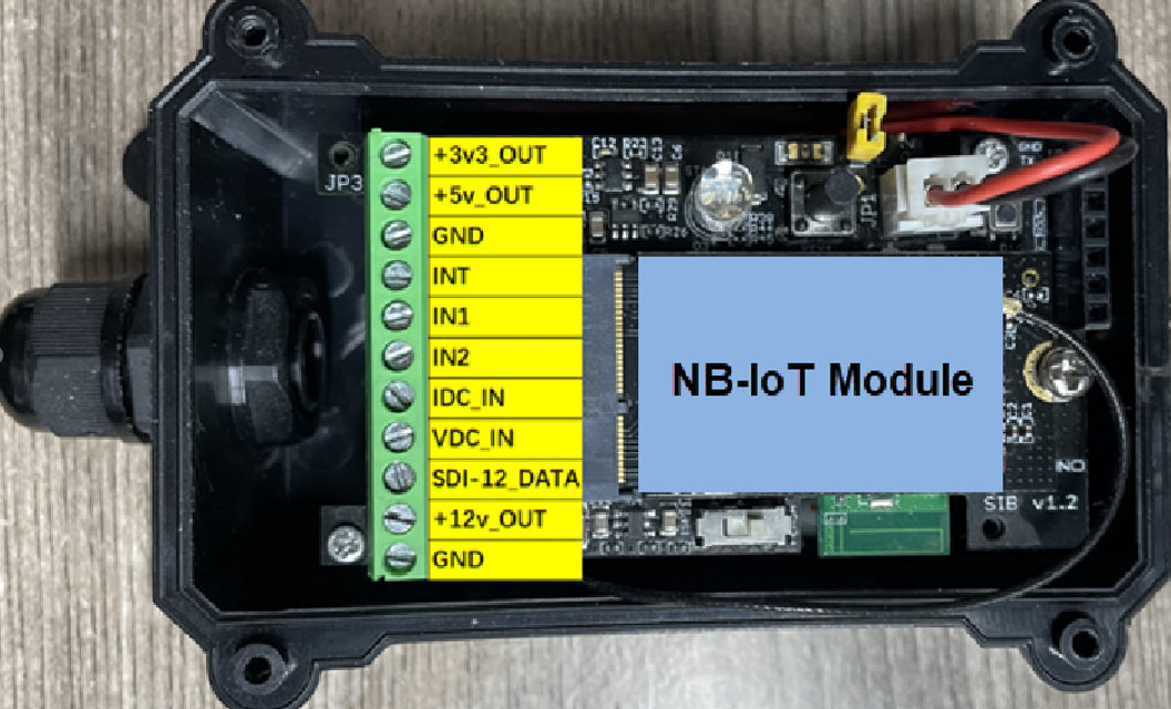
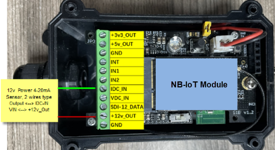
1.9 Pin Definitions , Switch & SIM Direction
PS-KN use the mother board which as below.
1.9.1 Jumper JP2
Power on Device when put this jumper.
1.9.2 BOOT MODE / SW1
- ISP: upgrade mode, device won't have any signal in this mode. but ready for upgrade firmware. LED won't work. Firmware won't run. 2) Flash: work mode, device starts to work and send out console output for further debug
1.9.3 Reset Button
Press to reboot the device.
1.9.4 SIM Card Direction
See this link. How to insert SIM Card.
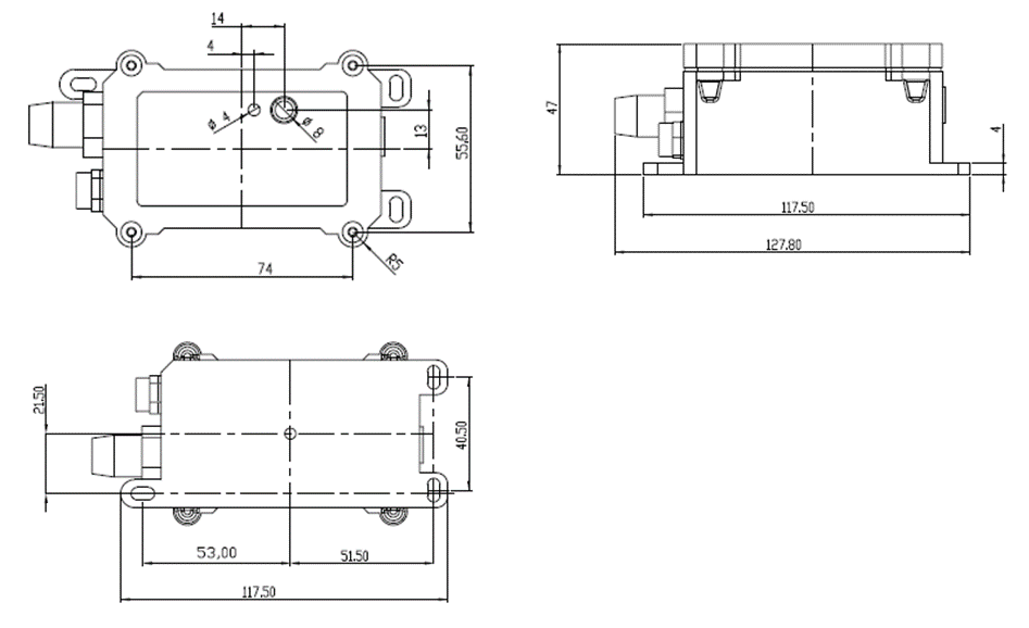
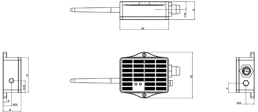
1.10 Mechanical
1.10.1 For KN Version
1.10.2 For KS Version
2. Use PS-KN to communicate with IoT Server
2.1 Send data to IoT server via NB-IoT network
The PS-KN is equipped with a NB-IoT module, the pre-loaded firmware in PS-KN will get environment data from sensors and send the value to local NB-IoT network via the NB-IoT module. The NB-IoT network will forward this value to IoT server via the protocol defined by PS-KN.
Below shows the network structure:
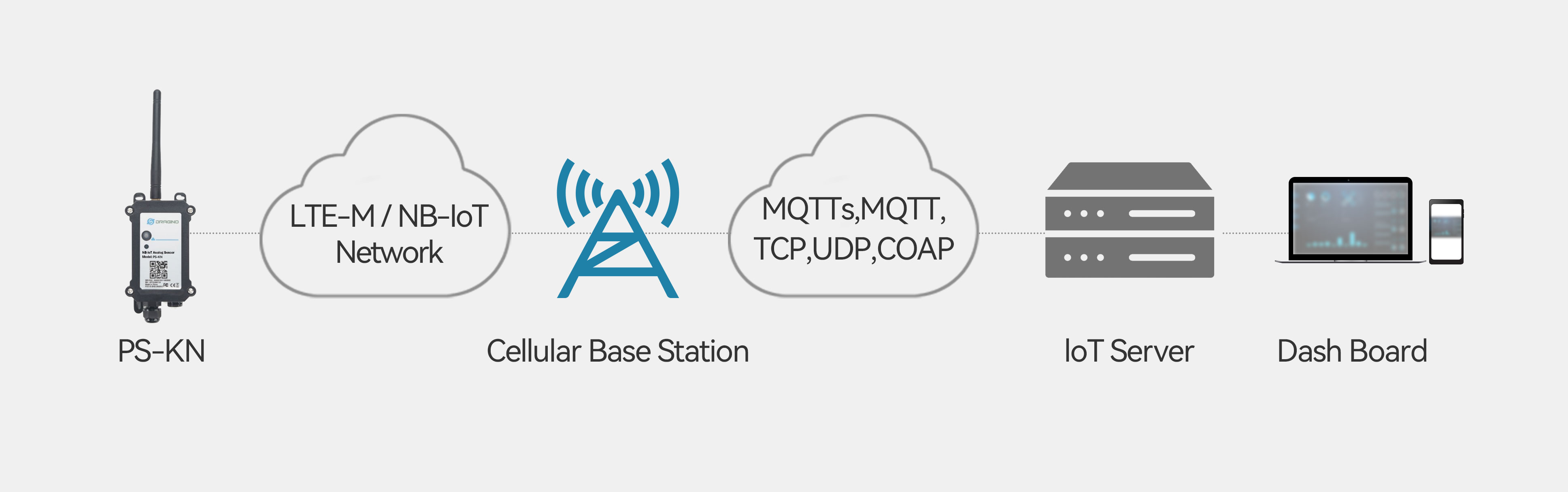
There are two version: -GE and -1T version of PS-KN. GE Version: This version doesn't include SIM card or point to any IoT server. User needs to use AT Commands to configure below two steps to set PS-KN send data to IoT server.
-
Install NB-IoT SIM card and configure APN. See instruction of Attach Network.
-
Set up sensor to point to IoT Server. See instruction of Configure to Connect Different Servers.
Below shows result of different server as a glance.
| Servers | Dash Board | Comments |
|---|---|---|
| Node-Red | 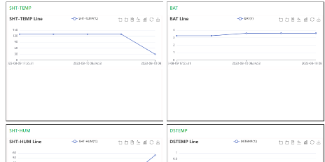 | |
| DataCake | 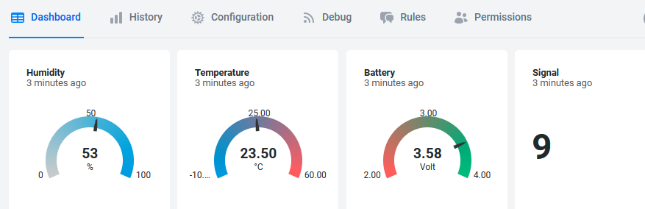 | |
| Tago.IO | ||
| General UDP | Raw Payload. Need Developer to design Dash Board | |
| General MQTT | Raw Payload. Need Developer to design Dash Board | |
| ThingSpeak | 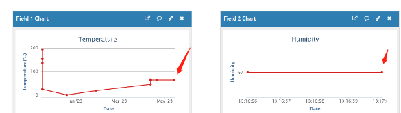 | |
| ThingsBoard | 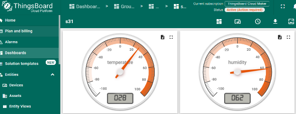 |
1T Version: This version has 1NCE SIM card pre-installed and configure to send value to ThingsEye. User Just need to select the sensor type in ThingsEyeand Activate PS-KN and user will be able to see data in ThingsEye. See here for ThingsEye Config Instruction.
2.2 Payload Types
To meet different server requirement, PS-KN supports different payload type.
Includes:
-
General JSON format payload. (Type=5)
-
HEX format Payload. (Type=0)
-
ThingSpeak Format. (Type=1)
-
ThingsBoard Format. (Type=3)
User can specify the payload type when choose the connection protocol. Example:
AT+PRO=2,0 // Use UDP Connection & hex Payload
AT+PRO=2,5 // Use UDP Connection & Json Payload
AT+PRO=3,0 // Use MQTT Connection & hex Payload
AT+PRO=3,1 // Use MQTT Connection & ThingSpeak
AT+PRO=3,3 // Use MQTT Connection & ThingsBoard
AT+PRO=3,5 // Use MQTT Connection & Json Payload
AT+PRO=4,0 // Use TCP Connection & hex Payload
AT+PRO=4,5 // Use TCP Connection & Json Payload
The following describes the latest payload.
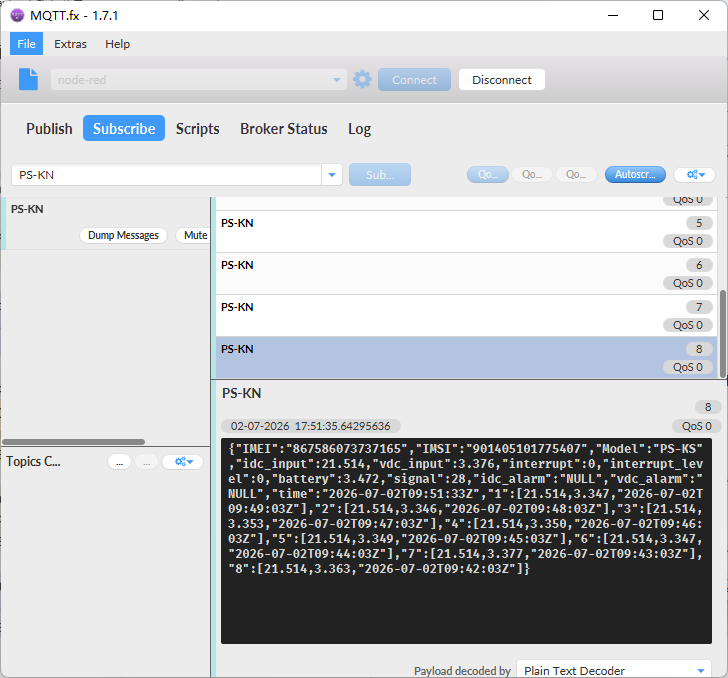
2.2.1 General Json Format(Type=5)
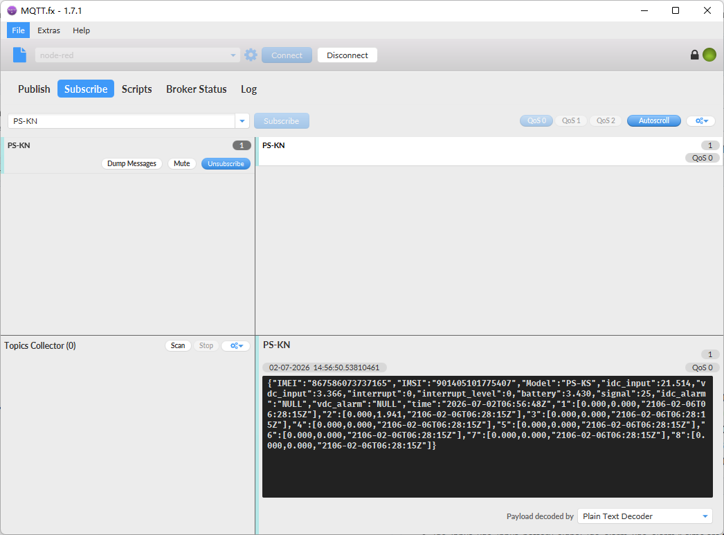
This is the General Json Format. As below:
{"IMEI":"867586073737165","IMSI":"901405101775407","Model":"PS-KS","idc_input":21.514,"vdc_input":3.366,"interrupt":0,"interrupt_level":0,"battery":3.430,"signal":25,"idc_alarm":"NULL","vdc_alarm":"NULL","time":"2026-07-02T06:56:48Z","1":[0.000,0.000,"2106-02-06T06:28:15Z"],"2":[0.000,1.941,"2106-02-06T06:28:15Z"],"3":[0.000,0.000,"2106-02-06T06:28:15Z"],"4":[0.000,0.000,"2106-02-06T06:28:15Z"],"5":[0.000,0.000,"2106-02-06T06:28:15Z"],"6":[0.000,0.000,"2106-02-06T06:28:15Z"],"7":[0.000,0.000,"2106-02-06T06:28:15Z"],"8":[0.000,0.000,"2106-02-06T06:28:15Z"]}
Notice, from above payload:
-
idc_input, vdc_input, battery, signal, idc_alarm, vdc_alarm & time are the value at uplink time.
-
Json entry 1 ~ 8 are the last 1 ~ 8 sampling data as specify by AT+CLOCKLOG=1,65535,15,8 Command. Each entry includes (from left to right): Idc_input , Vdc_input, Sampling time.
-
For idc_alarm and vdc_alarm, there are three possible states:
①When the uplink packet is not triggered by a ROC alarm, the status will be NULL.
②When the uplink packet is triggered by a ROC alarm due to incremental change exceeding the threshold, the status will be:
"idc_alarm": "IDC_INC"
"vdc_alarm": "IDC_INC"
③When the uplink packet is triggered by a ROC alarm due to decremental change exceeding the threshold, the status will be:
"idc_alarm": "IDC_DEC"
"vdc_alarm": "VDC_DEC"
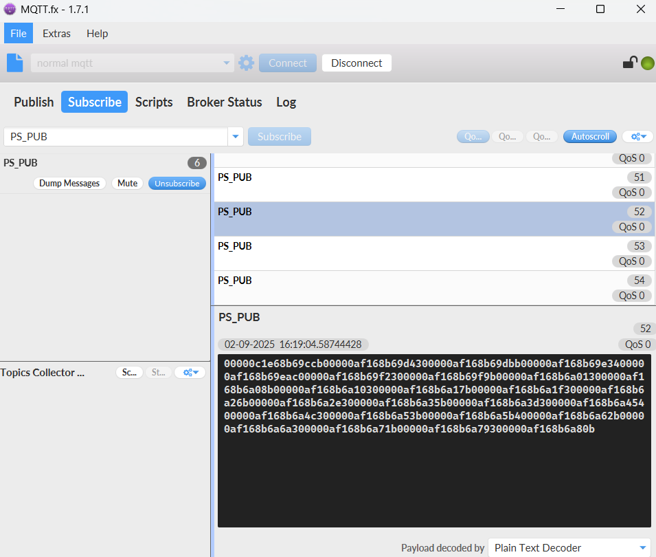
2.2.2 HEX format Payload(Type=0)
This is the HEX Format. As below:
f863663062798914f460087023300073017d0ccb1600000000000100000000195a687890ca0000000068788bbb000000006878883700000000687884b3000000006878812f0000000068787dab0000000068787a2700000000687876a300001d4168787321
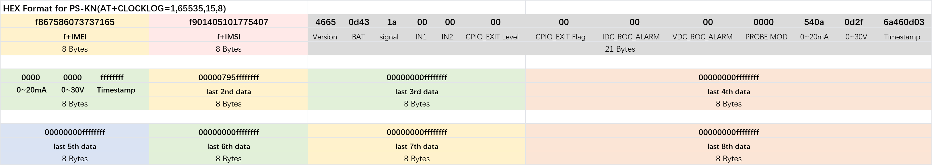
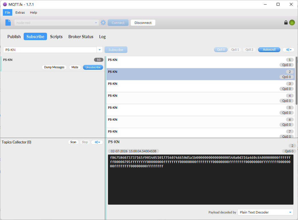
Device ID(f+IMEI): f867586073737165 = 867586073737165
SIM Card ID(f+IMSI): f901405101775407 = 901405101775407
Version:
These bytes include the hardware and software version.
Higher byte: Specify Sensor Model: 0x46 for PS-KN
Lower byte: Specify the software version: 0x65(H) = 101(D), means firmware version 1.0.1
BAT (Battery Info):
Check the battery voltage for PS-KN.
Ex1: 0x0d43 = 3395mV
Ex2: 0x0B49 = 2889mV
Signal Strength:
NB-IoT Network signal Strength.
Ex1: 0x1a = 26
0 -113dBm or less
1 -111dBm
2...30 -109dBm... -53dBm
31 -51dBm or greater
99 Not known or not detectable
IN1 & IN2:
IN1 and IN2 are used as Digital input pins.
Example:
01 (H): IN1 or IN2 pin is high level.
00 (L): IN1 or IN2 pin is low level.
GPIO_EXTI Level:
GPIO_EXTI is used as Interrupt Pin.
Example:
01 (H): GPIO_EXTI pin is high level.
00 (L): GPIO_EXTI pin is low level.
GPIO_EXTI Flag:
This data field shows if this packet is generated by Interrupt Pin or not.
Note: The Interrupt Pin is a separate pin in the screw terminal.
Example:
0x00: Normal uplink packet.
0x01: Interrupt Uplink Packet.
idc_roc_alarm
This data field indicates whether the uplink data packets are generated by the IDC's ROC alarm.
Example:
0x00: Normal uplink packet.
0x01: Uplink message triggered by ROC alarm due to incremental change exceeding the threshold.
0x02: Uplink message triggered by ROC alarm due to decremental change exceeding the threshold.
vdc_roc_alarmv
This data field indicates whether the uplink data packets are generated by the VDC's ROC alarm.
Example:
0x00: Normal uplink packet.
0x01: Uplink message triggered by ROC alarm due to incremental change exceeding the threshold.
0x02: Uplink message triggered by ROC alarm due to decremental change exceeding the threshold.
Probe Model:
PS-KN might connect to different kind of probes, 4~20mA represent the full scale of the measuring range. So a 12mA output means different meaning for different probe.
For example.
| Probe Type | 4~20mA scale for this probe | Example: 12mA actually meaning for this probe |
|---|---|---|
| PH Combination Electrodes | 0 ~ 14 pH | PH Value: 7 |
| Water Pressure Sensor | 0~5 meters | 2.5 meters pure water |
| Pressure transmitter probe | 0~1MPa | 0.5MPa air / gas or water pressure |
User can set different probe model for above probes. So IoT server is able to se identical how it should parse the 4~20mA or 0~30v sensor value and get the correct value.
0~20mA:
Example:
540a(H) = 21514 (D)/1000 = 21.514mA.
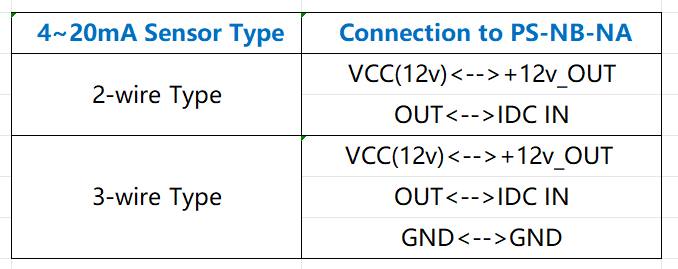
Connect to a 2 wire 4~20mA sensor.
0~30V:
Measure the voltage value. The range is 0 to 30V.
Example:
0d2f(H) = 3375(D)/1000= 3.375V
TimeStamp:
Unit TimeStamp Example: 6a460d03(H) = 1782975747(D)
Put the decimal value into this link( Epoch Converter )to get the time.
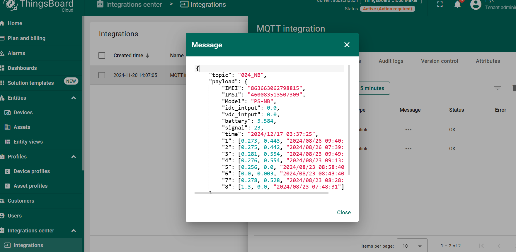
2.2.3 ThingsBoard Payload(Type=3)
Type3 payload special design for ThingsBoard, it will also configure other default server to ThingsBoard.
{ "topic": "004_NB", "payload": { "IMEI": "863663062798815", "IMSI": "460083513507309", "Model": "PS-KN", "idc_intput": 0.0, "vdc_intput": 0.0, "battery": 3.584, "signal": 23, "time": "2024/12/17 03:37:25", "1": [0.273, 0.443, "2024/08/26 09:40:35"], "2": [0.275, 0.442, "2024/08/26 07:39:55"], "3": [0.281, 0.554, "2024/08/23 09:49:04"], "4": [0.276, 0.554, "2024/08/23 09:13:40"], "5": [0.256, 0.0, "2024/08/23 08:58:40"], "6": [0.0, 0.003, "2024/08/23 08:43:40"], "7": [0.278, 0.528, "2024/08/23 08:28:40"], "8": [1.3, 0.0, "2024/08/23 07:48:31"] } }
2.3 Test Uplink and Change Update Interval
By default, sensor will send uplinks every 2 hours
User can use below commands to change the uplink interval.
AT Command: AT+TDC
Example: AT+TDC=7200 // Set Update Interval to 7200 seconds
Downlink Command: 0x01
Format: Command Code (0x01) followed by 3 bytes.
Example: 12 hours= 43200 seconds 43200(D)=0xA8C0(H)
Downlink Payload: 01 00 A8 C0 // AT+TDC=43200, Set Update Interval to 12 hours.
Note: User can also push the button for more than 1 second to activate an uplink.
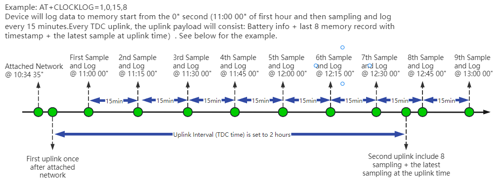
2.4 Multi-Samplings and One uplink(It is replaced by AT+CLOCKLOG
Sometimes when we deploy lots of end nodes in field. We want all sensors sample data at the same time, and upload these data together for analyze. In such case, we can use clock loging feature.
We can use this command to set the start time of data recording and the time interval to meet the requirements of the specific collection time of data.
- AT Command: AT+CLOCKLOG=a,b,c,d
a: 0: Disable Clock logging. **1:**Enable Clock Logging
b: Specify First sampling start second: range (0 ~ 3599, 65535) // **Note:**If parameter b is set to 65535, the log period starts after the node accesses the network and sends packets.
c: Specify the sampling interval: range (0 ~ 255 minutes)
d: How many entries should be uplink on every TDC (max 32)
Note: To disable clock recording, set the following parameters: AT+CLOCKLOG=1,65535,0,0
Example:
AT+CLOCKLOG=1,65535,1,8
After the node sends the first packet, data is recorded to the memory at intervals of 1 minute. For each TDC uplink, the uplink load will include: battery information + the last 8 memory records (payload + timestamp).
Note: Users need to synchronize the server time before configuring this command. If the server time is not synchronized before this command is configured, the command takes effect only after the node is reset.
- Downlink command: 0x03
Format: Command Code (0x03) followed by 5 bytes.
- Example 1: Downlink Payload:0301FFFF0F08 // Set SHT record time: AT+CLOCKLOG=1,65535,15,8
- Example 1: Downlink Payload:030104B00F08 // Set SHT record time: AT+CLOCKLOG=1,1200,15,8
Note: When entering the downlink payload, there must be no Spaces between bytes.
2.5 Trggier an uplink by external interrupt
PS-KN has an external trigger interrupt function. Users can use the GPIO_EXTI pin to trigger the upload of data packets.
AT command:
-
AT+INTMOD // Set the trigger interrupt mode
-
AT+INTMOD=0 // Disable Interrupt,as a digital input pin
-
AT+INTMOD=1 // Trigger by rising and falling edge
-
AT+INTMOD=2 // Trigger by falling edge
-
AT+INTMOD=3 // Trigger by rising edge
2.6 Set Power Output Duration
Control the output duration 3V3 , 5V or 12V. Before each sampling, device will
-
first enable the power output to external sensor,
-
keep it on as per duration, read sensor value and construct uplink payload
-
final, close the power output.
- Set extend the time of 3V3 power:
AT Command: AT+3V3T
| Command Example | Function | Response |
|---|---|---|
| AT+3V3T=? | Show 3V3 open time. | 0 OK |
| AT+3V3T=0 | Normally open 3V3 power supply. | OK default setting |
| AT+3V3T=1000 | Close after a delay of 1000 milliseconds. | OK |
| AT+3V3T=65535 | Normally closed 3V3 power supply. | OK |
Downlink Command: 0x0701
Example 1: Downlink Payload: 070101F4 --> AT+3V3T=500
Example 2: Downlink Payload: 0701FFFF --> AT+3V3T=65535
- Set extend the time of 5V power:
AT Command: AT+5VT
| Command Example | Function | Response |
|---|---|---|
| AT+5VT=? | Show 5V open time. | 0 OK |
| AT+5VT=0 | Normally closed 5V power supply. | OK default setting |
| AT+5VT=1000 | Close after a delay of 1000 milliseconds. | OK |
| AT+5VT=65535 | Normally open 5V power supply. | OK |
Downlink Command: 0x0702
Example 3: Downlink Payload: 070203E8 --> AT+5VT=1000
Example 4: Downlink Payload: 07020000 --> AT+5VT=0
- Set extend the time of 12V power:
AT Command: AT+12VT
| Command Example | Function | Response |
|---|---|---|
| AT+12VT=? | Show 12V open time. | 0 OK |
| AT+12VT=0 | Normally closed 12V power supply. | OK |
| AT+12VT=500 | Close after a delay of 500 milliseconds. | OK |
| AT+12VT=65535 | Normally open 5V power supply. | OK |
Downlink Command: 0x0703
Example 5: Downlink Payload: 070301F4 --> AT+12VT=500
Example 6: Downlink Payload: 07030000 --> AT+12VT=0
2.7 Set the Probe Model
Users need to configure this parameter according to the type of external probe. In this way, the server can decode according to this value, and convert the current value output by the sensor into water depth or pressure value.
AT Command: AT+PROBE
AT+PROBE=aabb
When aa=00, it is the water depth mode, and the current is converted into the water depth value; bb is the probe at a depth of several meters.
When aa=01, it is the pressure mode, which converts the current into a pressure value;
bb represents which type of pressure sensor it is.
| Command Example | Function | Response |
|---|---|---|
| AT +PROBE =? | Get or Set the probe model. | 0 OK |
| AT +PROBE =0003 | Set water depth sensor mode, 3m type. | OK |
| AT +PROBE =000A | Set water depth sensor mode, 10m type. | OK |
| AT +PROBE =0101 | Set pressure transmitters mode, first type. | OK |
| AT +PROBE =0000 | Initial state, no settings. | OK |
- Downlink command: 0x0A
Format: Command Code (0x08) followed by 2 bytes.
- Example 1: Downlink Payload: 080003 ---> AT+PROBE=0003
- Example 2: Downlink Payload: 080101 ---> AT+PROBE=0101
Note: When entering the downlink payload, there must be no Spaces between bytes.
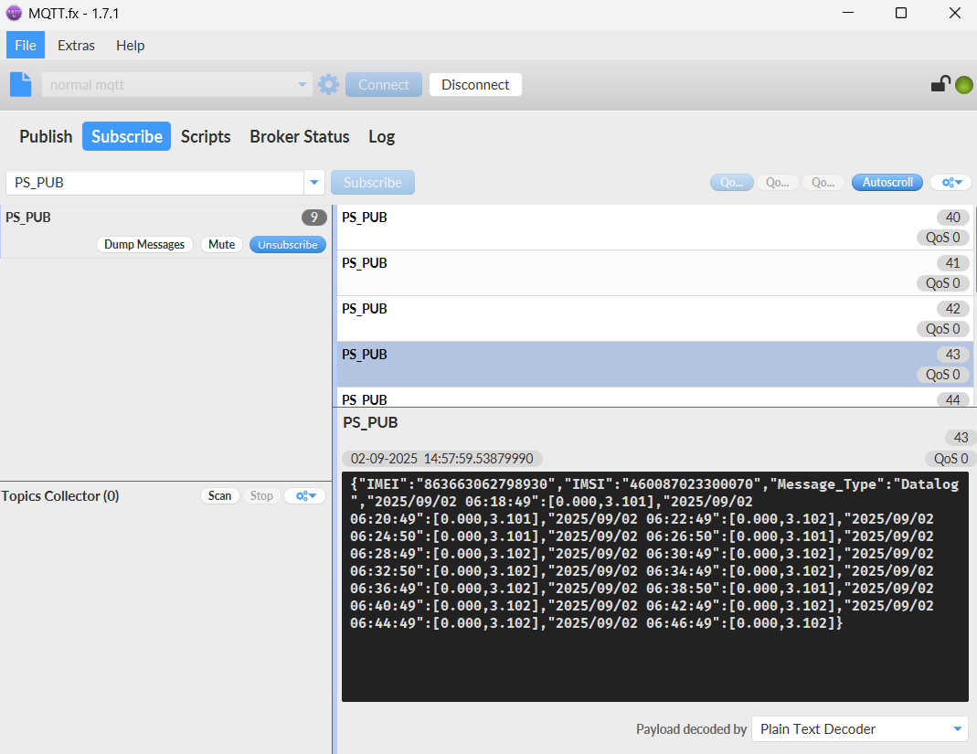
2.8 Datalog Function
Datalog Retransmission Function
Description:
The PS-KN supports data retransmission after offline recovery. When the device is offline, it continues to store data locally based on the sampling interval configured by AT+CLOCKLOG. Once the network is reconnected, the device will retransmit the stored data, with a maximum capacity of 1504 data sets.
AT Command:
AT+REDPT – Get or Set the data retransmission function after reconnecting to the network.
| Command Example | Function | Response |
|---|---|---|
| AT+REDPT=? | Query current retransmission status | 0 (default)ok |
| AT+REDPT=0 | Disable retransmission | ok |
| AT+REDPT=1 | Enable retransmission (max 1504 sets) | ok |
Downlink Command:
No downlink commands for this feature.
Note:
- Retransmission applies only to data stored during offline periods.
- The retransmission data format aligns with the data format set via AT+PRO, supporting both HEX and JSON formats.
Example:
- HEX format
The retransmitted HEX-formatted datalog is consistent with the datalog data format queried via the 0x31 command, with each data group comprising 8 bytes:
| Size(bytes) | 2 | 2 | 4 |
|---|---|---|---|
| value | 0~20mA | 0~30V | Timestamp |
- JSON format
When setting the payload format of AT+PRO to JSON, only the retransmitted datalog data uses the same JSON format as normal uplink data. The datalog queried via 0x31 is only available in HEX format.
2.10 Example Query saved historical records
- AT command: AT+CDP
This command can be used to search the saved history, recording up to 32 groups of data, each group of historical data contains a maximum of 100 bytes.
2.11 Scheduled domain name resolution
This command is used to set up scheduled domain name resolution.
AT command:
- AT+DNSTIMER// Unit: hour
After setting this command, domain name resolution will be performed regularly.
2.12 Set the QoS level
This command is used to set the QoS level of MQTT.
AT command:
- AT+MQOS// 0~2
Downlink command: 0x07
Format: Command Code (0x07) followed by 1 byte.
Ex1: Downlink payload: 0x0200 // AT+MQOS=0
Ex2: Downlink payload: 0x0201 // AT+MQOS=1
2.13 Set the downlink debugging mode
Feature: Enable or disable downlink debugging mode.
AT command: AT+DOWNTE
| Command Example | Function/Parameters | Response/Explanation |
|---|---|---|
| AT+DOWNTE=? | Get current Settings | 0,0 (default) OK |
| AT+DOWNTE=0,a | a: Enable/Disable downlink debugging | 0: Disable downlink debugging mode. 1: Enable downlink debugging mode (users can view original downlink messages). |
(Note: The first parameter is fixed to 0 and only the second parameter is configurable.)
Example:
- AT+DOWNTE=0,1 → Enable downlink debugging mode.
- AT+DOWNTE=0,0 → Disable downlink debugging mode.
Downlink Command:
No downlink commands for feature
2.14 Domain name resolution settings
Feature: Set dynamic domain name resolution IP.
AT command: AT+BKDNS
| Command Example | Function/Parameters | Response/Explanation |
| AT+BKDNS=? | Get current Settings | 0,0,NULL (default) OK |
| AT+BKDNS=a,b,c | a : Enable/Disable dynamic domain name resolution. |
1 : Disable dynamic domain name update. The ip address will be saved after the domain name is resolved, if the next domain name resolution fails, the last saved ip address will be used. 2 : Enable dynamic domain name update. The ip address will be saved after domain name resolution, if the next domain name resolution fails, the last saved ip address will be used, and the domain name resolution will be updated regularly according to the time set by the customer. |
| b : Set the time to update the domain name resolution at regular intervals. |
Unit: hour | |
| c : Set the IP address manually. |
The format is the same as AT+SERVADDR. If domain name resolution fails, this ip address will be used directly, if domain name resolution succeeds, parameter c will be updated to the successfully resolved IP address. |
Example:
- AT+BKDNS=1,0 // Dynamic domain name resolution is disabled.
- AT+BKDNS=2,1 // The dynamic domain name resolution function is enabled and the automatic update time is set to 1 hour.
- AT+BKDNS=2,4,3.69.98.183,1883 // The dynamic domain name resolution function is enabled and the automatic update time is set to 4 hour, and manually set the ip address, if the domain name failed to resolve, it will directly use this ip to communicate. When the next domain name resolution is successful, it will be updated to the ip address of the successful resolution.
Downlink Command:
No downlink command for this feature
2.15 Print last few data entries
Feature: Print the last few data entries
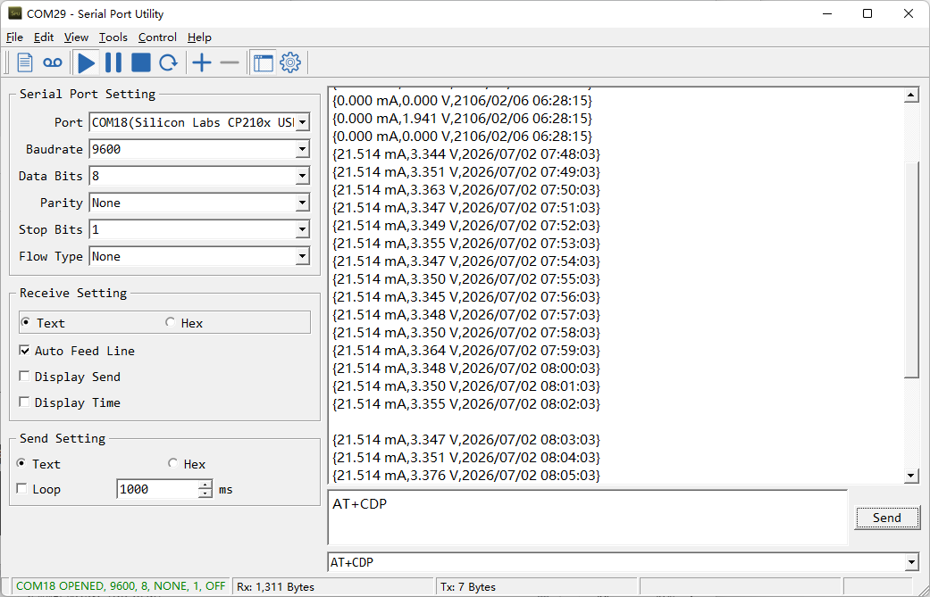
AT command: AT+PLDTA
| Command Example | 4 bytes |
|---|---|
| AT+PLDTA=5 Print last 5 entries | Stop Tx events when read sensor data 1 26/7/2 07:57:03 idc_input=21.514 vdc_input=3.348 2 26/7/2 07:58:03 idc_input=21.514 vdc_input=3.350 3 26/7/2 07:59:03 idc_input=21.514 vdc_input=3.364 4 26/7/2 08:00:03 idc_input=21.514 vdc_input=3.348 5 26/7/2 08:01:03 idc_input=21.514 vdc_input=3.350 OK |
Downlink Command:
No downlink command for this feature
2.16 Print data entries base on page
Feature: Print the sector data from start page to stop page.
AT command: AT+PDTA
| Command Example | 4 bytes |
|---|---|
| AT+PDTA=1,1 Print page 1 to 1 | Stop Tx events when read sensor data 8028A00 26/3/19 10:16:19 idc_input=0.000 vdc_input=0.000 8028A08 26/3/19 10:31:19 idc_input=0.000 vdc_input=0.000 8028A10 26/3/19 10:46:19 idc_input=0.000 vdc_input=0.000 8028A18 26/3/19 11:01:19 idc_input=0.000 vdc_input=0.000 8028A20 26/3/19 11:16:19 idc_input=0.000 vdc_input=0.000 8028A28 26/3/19 11:31:19 idc_input=0.000 vdc_input=0.000 8028A30 26/3/19 11:46:19 idc_input=0.000 vdc_input=0.000 8028A38 26/3/19 12:01:19 idc_input=0.000 vdc_input=0.000 8028A40 26/3/19 12:16:19 idc_input=0.000 vdc_input=0.000 8028A48 26/3/19 12:31:19 idc_input=0.000 vdc_input=0.000 8028A50 26/3/19 12:46:19 idc_input=0.000 vdc_input=0.000 8028A58 26/3/19 13:01:19 idc_input=0.000 vdc_input=0.000 8028A60 26/3/19 13:16:19 idc_input=0.000 vdc_input=0.000 8028A68 26/3/19 13:31:19 idc_input=0.000 vdc_input=0.000 8028A70 26/3/19 13:46:19 idc_input=0.000 vdc_input=0.000 8028A78 26/3/19 14:01:19 idc_input=0.000 vdc_input=0.00 OK |
Downlink Command:
No downlink command for this feature
2.17 Clear Flash Record
Feature: Clear flash storage for data log feature.
AT command: AT+CLRDTA
| Command Example | Function | Response |
|---|---|---|
| AT+CLRDTA | Clear date record | Stop Tx events,Please wait for the erase to complete Clear all stored sensor data... Start Tx events OK |
Downlink Command: 0x32
- Example: 0x32 00 // Same as AT+CLRDTA
2.18 Set device auto-reset time
Feature: Configure the device to automatically reset after a specified number of hours(Range: 0~255). AT command: AT+RESETTIME
| Command Example | Function/Parameters | Response |
|---|---|---|
| AT+RESETTIME=? | Get current settings | 0 OK |
| AT+RESETTIME= | Set auto-reset timer (in hours). 0: Disable auto-reset. >0: Reset after specified hours. | OK |
Example:
- AT+RESETTIME=24 // Device will reset every 24 hours.
- AT+RESETTIME=0 // Disable auto-reset (default).
Downlink Command:
No downlink command for this feature.
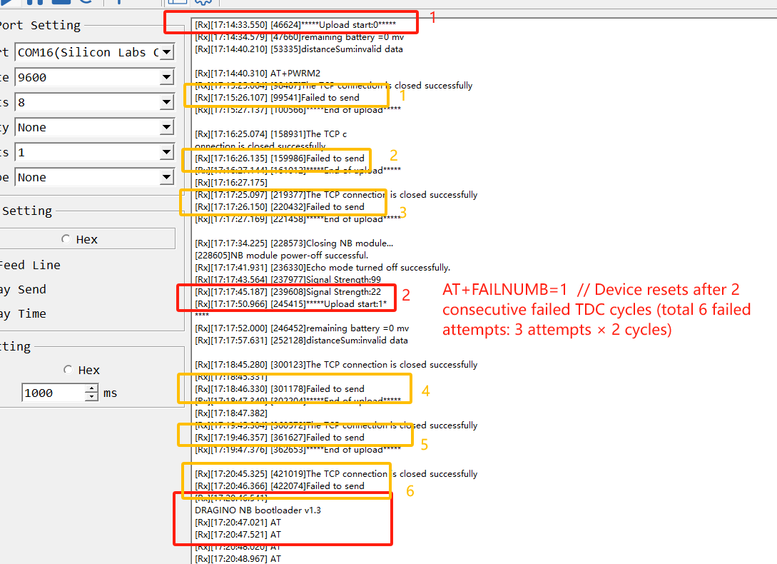
2.19 Set failure-triggered reset
Feature: Configure the number of consecutive failed transmission cycles (TDC periods) required to trigger an automatic device reset. (Each TDC period includes up to 3 transmission attempts.)
AT command: AT+FAILNUMB
| Command Example | Function/Parameters | Response |
|---|---|---|
| AT+FAILNUMB=? | Get current settings | 2 (default) OK |
| AT+FAILNUMB= | Set failure threshold: 0: Disable auto-reset function. 1-255: Number of consecutive failed TDC cycles to trigger reset. | OK |
Detailed Behavior:
- Each TDC period allows up to 3 transmission attempts for a single data packet.
- A "failed TDC cycle" means all 3 transmission attempts within that cycle failed.
- When the number of consecutive failed TDC cycles reaches the set threshold, the device will automatically reset.
Example:
- AT+FAILNUMB=0: Disables auto-reset (device will never reset due to transmission failures).
- AT+FAILNUMB=1: Device resets after 2 consecutive failed TDC cycles (total 6 failed attempts: 3 attempts × 2 cycles).
- AT+FAILNUMB=2: Device resets after 3 consecutive failed TDC cycles (total 9 failed attempts: 3 attempts × 3 cycles) - Default setting.
- AT+FAILNUMB=3: Device resets after 4 consecutive failed TDC cycles (total 12 failed attempts).
Note:
- The counter resets after any successful transmission.
- Maximum settable value is 255 (would require 256 consecutive failed TDC cycles to trigger reset).
Downlink Command:
No downlink command for this feature.
2.20 Report on Change Feature
Function Overview
The ROC feature monitors changes in IDC (current) and VDC (voltage) by setting a detection interval and change thresholds. When changes exceed the configured thresholds, the device sends an ROC uplink message and refreshes the comparison value.
AT Command Syntax
- AT+ROC=? // Query current ROC settings
- AT+ROC=0,0,0,0 // Disable ROC function
- AT+ROC=1,[interval],[idc_threshold],[vdc_threshold] // Enable ROC mode 1
- AT+ROC=2,[interval],[idc_threshold],[vdc_threshold] // Enable ROC mode 2
Parameters
Mode (first parameter)
0: Function disabled.
1: ROC mode 1 - Sends ROC uplink and refreshes comparison value when change exceeds threshold.
2: ROC mode 2 - Additionally refreshes comparison value during regular transmissions (TDC, manual, etc.).
interval
Detection interval in seconds (0~65535).
idc_threshold
Current change threshold in microamperes (μA).
vdc_threshold
Voltage change threshold in millivolts (mV).
Mode Differences
Mode 1: Only updates comparison value when ROC threshold is exceeded.
Mode 2: Updates comparison value both when threshold is exceeded and during regular transmissions (TDC, manual, etc.).
AT Command Examples
- AT+ROC=1,60,3000,500 //Checks every 60 seconds. Sends ROC uplink if current changes >3000μA (3mA) or voltage changes >500mV, then refreshes comparison values.
- AT+ROC=1,60,3000,0 //Checks every 60 seconds. Only monitors current changes (>3mA). Setting vdc_threshold=0 disables voltage monitoring.
- AT+ROC=2,120,3000,500 //Checks every 120 seconds. Sends ROC uplink if current changes >3000μA (3mA) or voltage changes >500mV. Refreshes comparison value both when threshold is exceeded and during regular transmissions.
- AT+ROC=2,120,0,500 //Checks every 120 seconds for voltage changes (>500mV). Refreshes comparison value both when threshold is exceeded and during regular transmissions.
Downlink Command Format(8 bytes)
Structure: 0x09 aa bb bb cc cc dd dd
| Byte Position | Field | Description | Example Values |
|---|---|---|---|
| 1 | Function Code | Always 0x09 for ROC configuration. | 09 |
| 2 | a: Mode | 00: OFF 01: Mode 1 02: Mode 2 | 01 //ROC mode 1 |
| 3-4 | b: Interval | Detection interval in seconds. | 00 3C //60s |
| 5-6 | c: IDC Threshold | Current change threshold in μA. | 0B B8 //3000μA |
| 7-8 | d: VDC Threshold | Voltage change threshold in mV. | 01 F4 //500mV |
Downlink Examples
- 09 01 00 3C 0B B8 01 F4 //Equivalent to AT+ROC=1,60,3000,500
- 09 02 00 78 00 00 01 F4 //Equivalent to AT+ROC=2,120,0,500
- 09 02 00 78 0B B8 01 F4 //Equivalent to AT+ROC=2,120,3000,500
3. Configure PS-KN
3.1 Configure Methods
PS-KN supports below configure method:
-
AT Command via Bluetooth Connection (Recommended): BLE Configure Instruction.
-
AT Command via UART Connection : See UART Connection.
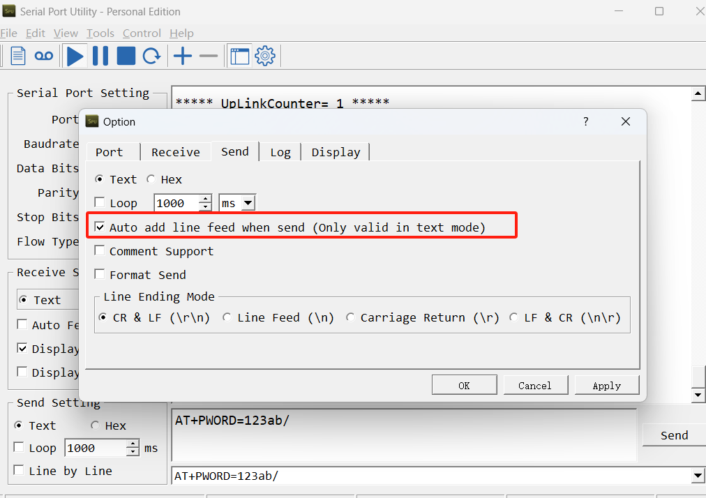
3.2 Serial Access Password
After the Bluetooth or UART connection is successful, use the Serial Access Password to enter the AT command window.
The label on the box of the node will print the initial password: AT+PIN=xxxxxx, and directly use the six-digit password to access the AT instruction window.
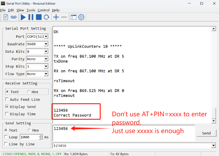
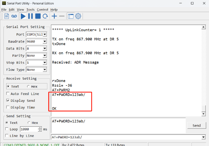
If you need to change the password, use AT+PWORD=xxxxxx (6 characters), NB nodes only support lowercase letters.
Note: After entering the command, you need to add a line break, and you can also set automatic line breaks in the Bluetooth tool or UART connection tool.
3.3 AT Commands Set
AT+<CMD>? : Help on <CMD>
AT+<CMD> : Run <CMD>
AT+<CMD>=<value> : Set the value
AT+<CMD>=? : Get the value
AT : Attention
AT? : Short Help
ATZ : MCU Reset
AT+TDC : Application Data Transmission Interval
AT+CFG : Print all configurations
AT+MODEL :Get module information
AT+SLEEP :Get or set the sleep status
AT+DEUI : Get or set the Device ID
AT+INTMOD : Set the trigger interrupt mode
AT+APN : Get or set the APN
AT+3V3T : Set extend the time of 3V3 power
AT+5VT : Set extend the time of 5V power
AT+12VT : Set extend the time of 12V power
AT+PROBE : Get or Set the probe model
AT+PRO : Choose agreement
AT+RXDL : Extend the sending and receiving time
AT+TR : Get or set data record time
AT+CDP : Read or Clear cached data
AT+NOUD : Get or Set the number of data to be uploaded
AT+DNSCFG : Get or Set DNS Server
AT+CSQTIME : Get or Set the time to join the network
AT+DNSTIMER : Get or Set the NDS timer
AT+TLSMOD : Get or Set the TLS mode
AT+GETSENSORVALUE : Returns the current sensor measurement
AT+SERVADDR : Server Address
MQTT Management
AT+CLIENT : Get or Set MQTT client
AT+UNAME : Get or Set MQTT Username
AT+PWD : Get or Set MQTT password
AT+PUBTOPIC : Get or Set MQTT publish topic
AT+SUBTOPIC : Get or Set MQTT subscription topic
Information
AT+FDR : Factory Data Reset
AT+PWORD : Serial Access Password
AT+LDATA : Get the last upload data
AT+CDP : Read or Clear cached data
4. Battery & Power Consumption
PS-KN use Charging Pad + 1000mAh Li-ion Battery pack. See below link for detail information about the battery info and how to replace.
Battery Info & Power Consumption Analyze .
5. Firmware update
User can change device firmware to:
-
Update with new features.
-
Fix bugs.
Firmware and changelog can be downloaded from : Firmware download link
Methods to Update Firmware:
-
(Recommended way) OTA firmware update via BLE: Instruction.
-
Update through UART TTL interface : Instruction.
6. FAQ
6.1 How can I access t EG800-NGFF AT Commands?
User can access to EG800-NGFF directly and send AT Commands.
6.2 Why is there no LED response when I press the button on the solar panel model?
If the LED does not light up when you press the button, it may be because the battery has entered protection mode.
Solution: To reactivate the battery, simply expose the solar panel to direct sunlight. For more details, please refer to: Battery Protection State (Apply to Solar Panel + Li-ion battery)
7. Order Info
Part Number: PS-KN-XX-YY
XX:
-
GE: General version ( Exclude SIM card)
-
1T: with 1NCE * 10 years 500MB SIM card and Pre-configure to ThingsEye server
YY: The grand connector hole size
-
M12: M12 hole
-
M16: M16 hole
-
M20: M20 hole
8. Packing Info
Package Includes:
-
PS-KN NB-IoT Analog Sensor x 1
-
External antenna x 1
Dimension and weight:
Package Size / pcs :
- For PS-KN: mm
- For PS-KS: mm
Weight / pcs :
- For PS-KN: g
- For PS-KS: g
9. Support
-
Support is provided Monday to Friday, from 09:00 to 18:00 GMT+8. Due to different timezones we cannot offer live support. However, your questions will be answered as soon as possible in the before-mentioned schedule.
-
Provide as much information as possible regarding your enquiry (product models, accurately describe your problem and steps to replicate it etc) and send a mail to support@dragino.com.