RS485-BL – Waterproof RS485 to LoRaWAN Converter
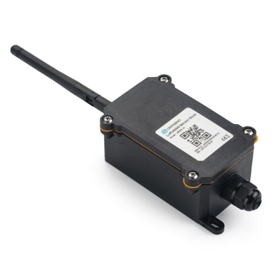
Table of Contents:
- 1. Introduction
- 2. Pin mapping and Power ON Device
- 3. Operation Mode
- 3.1 How it works?
- 3.2 Example to join LoRaWAN network
- 3.3 Configure Device to Read RS485 Sensor
- 3.4 Uplink Payload
- 3.5 Configure RS485-BL via AT or Downlink
- 3.5.1 Common Commands:
- 3.5.2 Sensor related commands:
- Choose Device Type (RS485 or TTL) (Since v1.3.3)
- RS485 Debug Command (AT+CFGDEV)
- Set Payload version
- Set RS485 Sampling Commands
- Fast command to handle MODBUS device
- RS485 command timeout
- Uplink payload mode
- Cut data separation processing(Since Version 1.4.2)
- Manually trigger an Uplink
- Clear RS485 Command
- Set Serial Communication Parameters
- Configure Databit(Since version 1.4.0)
- Encrypted payload
- Get sensor value
- Resets the downlink packet count
- When the limit bytes are exceeded, upload in batches
- Copy downlink to uplink
- Query version number and frequency band 、TDC
- Control output power duration
- 3.6 Connect to external temperature sensor & counting sensor
- 3.7 Buttons
- 3.8 +3V3 Output (Since v1.3.3)
- 3.9 +5V Output (Since v1.3.3)
- 3.10 LEDs
- 3.11 Switch Jumper
- 3.12 Battery & Power Consumption
- 4. Case Study
- 5. Use AT Command
- 6. FAQ
- 6.1 How to upgrade the image?
- 6.2 How to change the LoRa Frequency Bands/Region?
- 6.3 How many RS485-Slave can RS485-BL connects?
- 6.4 How to Use RS485-BL to connect to RS232 devices?
- 6.5 How to judge whether there is a problem with the set COMMAND
- 6.6 Where to get the decoder for RS485-BL?
- 6.7 Why does my TTL sensor have returned data, but after using the command AT+DATACUT, the data in the payload is 0?
- 6.8 Where can I get a decoder?
- 6.9 How to configure RS485 commands more conveniently?
- 7. Trouble Shooting
- test
- 8. Order Info
- 9. Packing Info
- 10. Support
1. Introduction
1.1 What is RS485-BL RS485 to LoRaWAN Converter
The Dragino RS485-BL is a RS485 / UART to LoRaWAN Converter for Internet of Things solutions. User can connect RS485 or UART sensor to RS485-BL converter, and configure RS485-BL to periodically read sensor data and upload via LoRaWAN network to IoT server.
RS485-BL can interface to RS485 sensor, 3.3v/5v UART sensor or interrupt sensor. RS485-BL provides a 3.3v output and a 5v output to power external sensors. Both output voltages are controllable to minimize the total system power consumption.
RS485-BL is IP67 waterproof and powered by 8500mAh Li-SOCI2 battery, it is designed for long term use for several years.
RS485-BL runs standard LoRaWAN 1.0.3 in Class A. It can reach long transfer range and easy to integrate with LoRaWAN compatible gateway and IoT server.
For data uplink, RS485-BL sends user-defined commands to RS485 devices and gets the return from the RS485 devices. RS485-BL will process these returns data according to user-define rules to get the final payload and upload to LoRaWAN server.
For data downlink, RS485-BL runs in LoRaWAN Class A. When there is downlink commands from LoRaWAN server, RS485-BL will forward the commands from LoRaWAN server to RS485 devices.
Each RS485-BL pre-load with a set of unique keys for LoRaWAN registration, register these keys to LoRaWAN server and it will auto connect after power on.
1.2 Specifications
Operate Temperature:
- -40°C ~ 65°C
Hardware System:
- STM32L072xxxx MCU
- SX1276/78 Wireless Chip
- Power Consumption (exclude RS485 device):
- Idle: 6uA@3.3v
- 20dB Transmit: 130mA@3.3v
- 5V sampling maximum current:500mA
Interface for Model:
- 1 x RS485 Interface
- 1 x TTL Serial , 3.3v or 5v.
- 1 x I2C Interface, 3.3v or 5v.
- 1 x one wire interface
- 1 x Interrupt Interface
- 1 x Controllable 5V output, max
LoRa Spec:
- Frequency Range:
- Band 1 (HF): 862 ~ 1020 Mhz
- Band 2 (LF): 410 ~ 528 Mhz
- 168 dB maximum link budget.
- +20 dBm - 100 mW constant RF output vs.
- Programmable bit rate up to 300 kbps.
- High sensitivity: down to -148 dBm.
- Bullet-proof front end: IIP3 = -12.5 dBm.
- Excellent blocking immunity.
- Fully integrated synthesizer with a resolution of 61 Hz.
- LoRa modulation.
- Built-in bit synchronizer for clock recovery.
- Preamble detection.
- 127 dB Dynamic Range RSSI.
- Automatic RF Sense and CAD with ultra-fast AFC.
1.3 Features
- LoRaWAN Class A & Class C protocol (default Class A)
- Frequency Bands: CN470/EU433/KR920/US915/EU868/AS923/AU915/IN865/RU864/MA869
- AT Commands to change parameters
- Remote configure parameters via LoRaWAN Downlink
- Firmware upgradable via program port
- Support multiply RS485 devices by flexible rules
- Support Modbus protocol
- Support Interrupt uplink
1.4 Applications
- Smart Buildings & Home Automation
- Logistics and Supply Chain Management
- Smart Metering
- Smart Agriculture
- Smart Cities
- Smart Factory
1.5 Firmware Change log
RS485-BL Image files – Download link and Change log
1.6 Hardware Change log
v1.4
1. Change Power IC to TPS22916
v1.3
1. Change JP3 from KF350-8P to KF350-11P, Add one extra interface for I2C and one extra interface for one-wire
v1.2
Release version
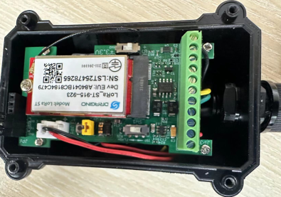
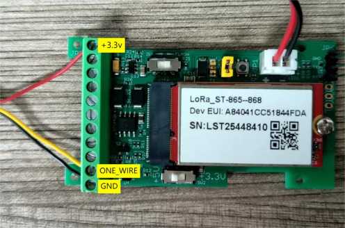
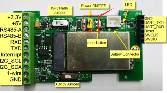
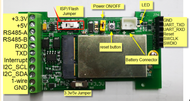
2. Pin mapping and Power ON Device
The RS485-BL is powered on by 8500mAh battery. To save battery life, RS485-BL is shipped with power off. User can put the jumper to power on RS485-BL.
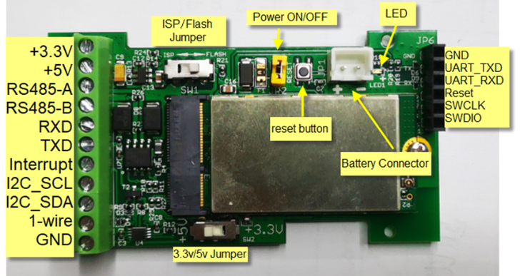
The Left TXD and RXD are TTL interface for external sensor. TTL level is controlled by 3.3/5v Jumper.
3. Operation Mode
3.1 How it works?
The RS485-BL is configured as LoRaWAN OTAA Class A mode by default. It has OTAA keys to join network. To connect a local LoRaWAN network, user just need to input the OTAA keys in the network server and power on the RS485-BL. It will auto join the network via OTAA.
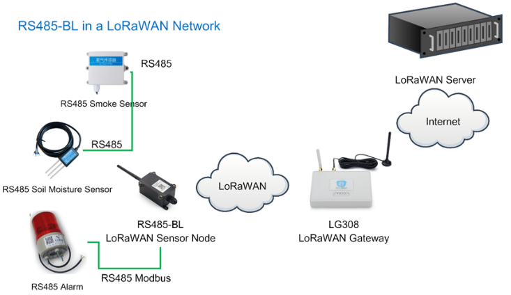
3.2 Example to join LoRaWAN network
Here shows an example for how to join the TTN V3 Network. Below is the network structure, we use LG308 as LoRaWAN gateway here.
The RS485-BL in this example connected to two RS485 devices for demonstration, user can connect to other RS485 devices via the same method.
The LG308 is already set to connect to TTN V3 network . So what we need to now is only configure the TTN V3:
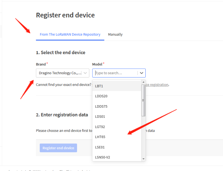
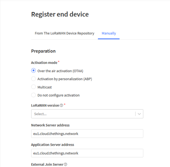
Step 1: Create a device in TTN V3 with the OTAA keys from RS485-BL.
Each RS485-BL is shipped with a sticker with unique device EUI:
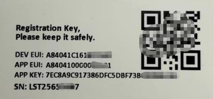
User can enter this key in their LoRaWAN Server portal. Below is TTN V3 screen shot:
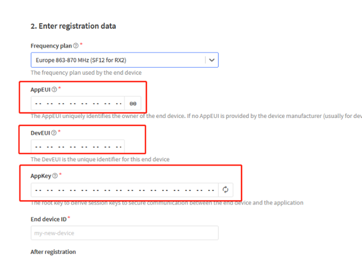
Add APP EUI in the application.
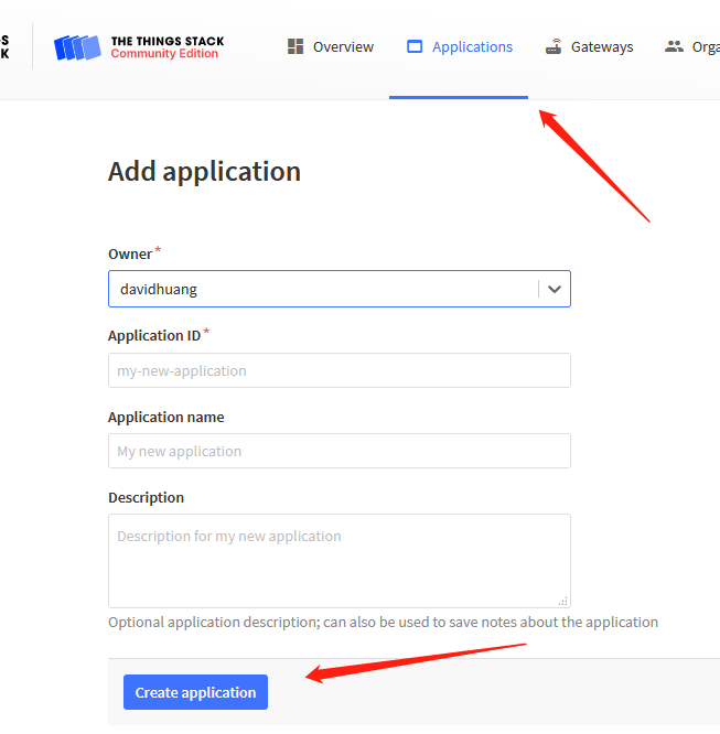
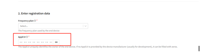
You can also choose to create the device manually.
Add APP KEY and DEV EUI
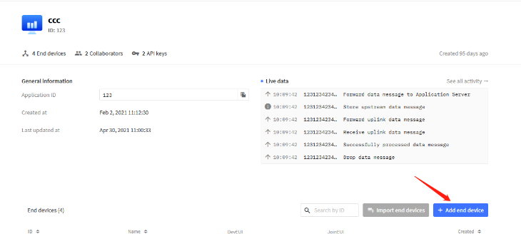
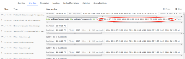
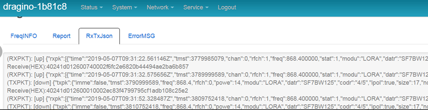
Step 2: Power on RS485-BL and it will auto join to the TTN V3 network. After join success, it will start to upload message to TTN V3 and user can see in the panel.
3.3 Configure Device to Read RS485 Sensor
There are plenty of RS485 and TTL level devices in the market and each device has different commands to read the valid data. To support these devices in most flexible, RS485-BL supports flexible command set. User can use Dragino RS485 Tool, AT Commands or LoRaWAN Downlink Command to configure how RS485-BL should read the sensor and how to handle the return from RS485 or TTL sensors.
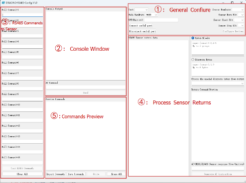
3.3.1 Method 1 -- via RS485 Configure Tool
Use the RS485 Configure tool is the recommand method. Please see the instruction of how to use the tool:
3.3.2 Method 2 -- via AT Commands
3.3.2.1 Configure UART settings for RS485 or TTL communication(Since v1.3.3)
RS485-BL can connect to either RS485 sensors or TTL sensor. User need to specify what type of sensor need to connect.
1. RS485-MODBUS mode:
AT+MOD=1 // Support RS485-MODBUS type sensors. User can connect multiply RS485 , Modbus sensors to the A / B pins.
2. TTL mode:
AT+MOD=2 // Support TTL Level sensors, User can connect one TTL Sensor to the TXD/RXD/GND pins.
RS485-BL default UART settings is 9600, no parity, stop bit 1. If the sensor has a different settings, user can change the RS485-BL setting to match.
AT Commands | Description | Example |
|---|---|---|
AT+BAUDR | Set the baud rate (for RS485 connection). | AT+BAUDR=9600 Options: (1200,2400,4800,14400,19200,115200) |
AT+PARITY | Set UART parity (for RS485 connection) Default Value is: no parity. | AT+PARITY=0 Option: 0: no parity, 1: odd parity, 2: even parity |
AT+STOPBIT | Set serial stopbit (for RS485 connection) Default Value is: 1bit. | AT+STOPBIT=0 for 1bit AT+STOPBIT=1 for 1.5 bit AT+STOPBIT=2 for 2 bits |
Example(Soil three-parameter detector):
Wiring the UART sensor
GND <--------> GND
TX <--------> RX
RX <--------> TX
VCC <--------> 3.3/5V
Set the correct configuration:
AT+BAUDR=9600
AT+PARITY=0
AT+STOPBIT=1
If the sensor needs 5v. Need to move the switch position to 5v and then use the command
AT+5VT=30000
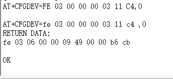
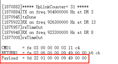
Configuration read command:
AT+CFGDEV=FE 03 00 00 00 03 11 C4,0
FE: Station address
03: Function code
00 00: Register start address
00 03: Number of registers
11 04: Check code
Use AT+COMMAND1 to set it as a command, and use AT+DATACUT1 to intercept the bytes I need
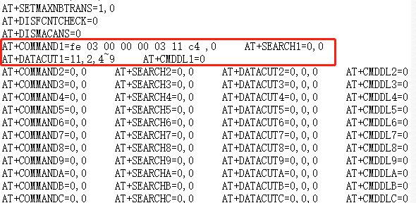
upload payload:
3.3.3 Configure sensors
Some sensors might need to configure before normal operation. User can configure such sensor via PC or through RS485-BL AT Commands AT+CFGDEV.
When user issue an AT+CFGDEV command, Each AT+CFGDEV equals to send a command to the RS485 or TTL sensors. This command will only run when user input it and won't run during each sampling.
| AT Commands | Description | Example |
|---|---|---|
| AT+CFGDEV | This command is used to configure the RS485/TTL devices; they won’t be used during sampling. AT+CFGDEV=xx xx xx xx xx xx xx xx xx xx xx xx, mm: 0: no CRC, 1: add CRC-16/MODBUS in the end of this command | AT+CFGDEV=xx xx xx xx xx xx xx xx xx xx xx xx,m |
Detail of AT+CFGDEV command see AT+CFGDEV detail.
3.3.4 Configure read commands for each sampling
RS485-BL is a battery powered device; it will sleep most of time. And wake up on each period and read RS485 / TTL sensor data and uplink.
During each sampling, we need to confirm what commands we need to send to the sensors to read data. After the RS485/TTL sensors send back the value, it normally includes some bytes and we only need a few from them for a shorten payload.
To save the LoRaWAN network bandwidth, we might need to read data from different sensors and combine their valid value into a short payload.
This section describes how to achieve above goals.
During each sampling, the RS485-BL can support 15 commands to read sensors. And combine the return to one or several uplink payloads.
Command from RS485-BL to Sensor:
RS485-BL can send out pre-set max 15 strings via AT+COMMAD1, ATCOMMAND2,…, to AT+COMMANDF . All commands are of same grammar.
Handle return from sensors to RS485-BL:
After RS485-BL send out a string to sensor, RS485-BL will wait for the return from RS485 or TTL sensor. And user can specify how to handle the return, by AT+DATACUT or AT+SEARCH commands
AT+DATACUT
When the return value from sensor have fix length and we know which position the valid value we should get, we can use AT+DATACUT command.
AT+SEARCH
When the return value from sensor is dynamic length and we are not sure which bytes the valid data is, instead, we know what value the valid value following. We can use AT+SEARCH to search the valid value in the return string.
Define wait timeout:
Some RS485 device might has longer delay on reply, so user can use AT+CMDDL to set the timeout for getting reply after the RS485 command is sent. For example, AT+CMDDL1=1000 to send the open time to 1000ms
After we got the valid value from each RS485 commands, we need to combine them together with the command AT+DATAUP.
Examples:
Below are examples for the how above AT Commands works.
AT+COMMANDx : This command will be sent to RS485/TTL devices during each sampling, Max command length is 14 bytes. The grammar is:
AT+COMMANDx=xx xx xx xx xx xx xx xx xx xx xx xx,m xx xx xx xx xx xx xx xx xx xx xx xx: The RS485 command to be sent m: 0: no CRC, 1: add CRC-16/MODBUS in the end of this command |
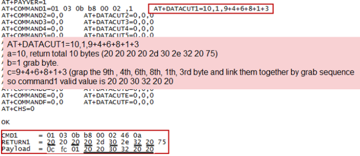
For example, if we have a RS485 sensor. The command to get sensor value is: 01 03 0B B8 00 02 46 0A. Where 01 03 0B B8 00 02 is the Modbus command to read the register 0B B8 where stored the sensor value. The 46 0A is the CRC-16/MODBUS which calculate manually.
In the RS485-BL, we should use this command AT+COMMAND1=01 03 0B B8 00 02,1 for the same.
AT+SEARCHx: This command defines how to handle the return from AT+COMMANDx.
AT+SEARCHx=aa,xx xx xx xx xx
|
Examples:
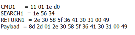
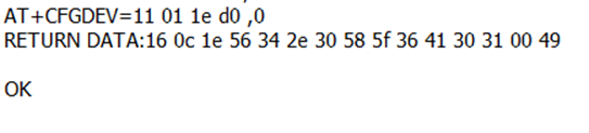
1) For a return string from AT+COMMAND1: 16 0c 1e 56 34 2e 30 58 5f 36 41 30 31 00 49
If we set AT+SEARCH1=1,1E 56 34. (max 5 bytes for prefix)
The valid data will be all bytes after 1E 56 34 , so it is 2e 30 58 5f 36 41 30 31 00 49
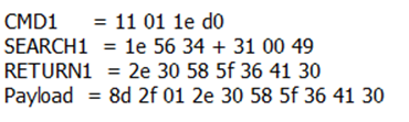
2) For a return string from AT+COMMAND1: 16 0c 1e 56 34 2e 30 58 5f 36 41 30 31 00 49
If we set AT+SEARCH1=2, 1E 56 34+31 00 49
Device will search the bytes between 1E 56 34 and 31 00 49. So it is 2e 30 58 5f 36 41 30
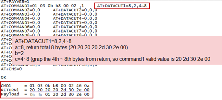
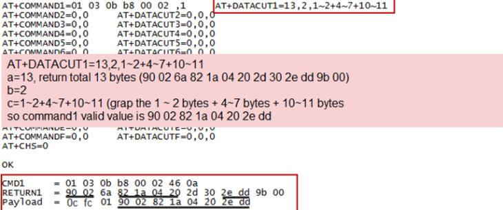
AT+DATACUTx : This command defines how to handle the return from AT+COMMANDx, max return length is 100 bytes.(Since 1.4.0)
AT+DATACUTx=a,b,c
|
Examples:
Grab bytes:
Grab a section.
Grab different sections.
Note:
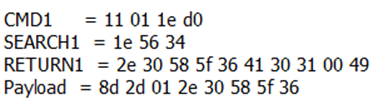
AT+SEARCHx and AT+DATACUTx can be used together, if both commands are set, RS485-BL will first process AT+SEARCHx on the return string and get a temporary string, and then process AT+DATACUTx on this temporary string to get the final payload. In this case, AT+DATACUTx need to set to format AT+DATACUTx=0,xx,xx where the return bytes set to 0.
Example:
AT+COMMAND1=11 01 1E D0,0
AT+SEARCH1=1,1E 56 34
AT+DATACUT1=0,2,1~5
Return string from AT+COMMAND1: 16 0c 1e 56 34 2e 30 58 5f 36 41 30 31 00 49
String after SEARCH command: 2e 30 58 5f 36 41 30 31 00 49
Valid payload after DataCUT command: 2e 30 58 5f 36
3.3.4 Compose the uplink payload
Through AT+COMMANDx and AT+DATACUTx we got valid value from each RS485 commands, Assume these valid value are RETURN1, RETURN2, .., to RETURNx. The next step is how to compose the LoRa Uplink Payload by these RETURNs. The command is AT+DATAUP.
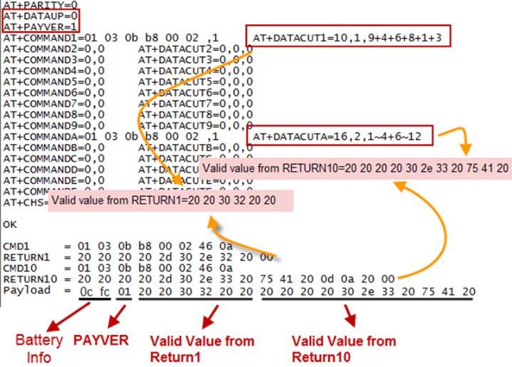
Examples: AT+DATAUP=0
Compose the uplink payload with value returns in sequence and send with A SIGNLE UPLINK.
Final Payload is
Battery Info+PAYVER + VALID Value from RETURN1 + Valid Value from RETURN2 + … + RETURNx
Where PAYVER is defined by AT+PAYVER, below is an example screen shot.
Examples: AT+DATAUP=1
Compose the uplink payload with value returns in sequence and send with Multiply UPLINKs.
Final Payload is
Battery Info+PAYVER + PAYLOAD COUNT + PAYLOAD# + DATA
Battery Info (2 bytes): Battery voltage
PAYVER (1 byte): Defined by AT+PAYVER
PAYLOAD COUNT (1 byte): Total how many uplinks of this sampling.
PAYLOAD# (1 byte): Number of this uplink. (from 0,1,2,3…,to PAYLOAD COUNT)
DATA: Valid value: max 6 bytes(US915 version here, Notice*!) for each uplink so each uplink <= 11 bytes. For the last uplink, DATA will might less than 6 bytes
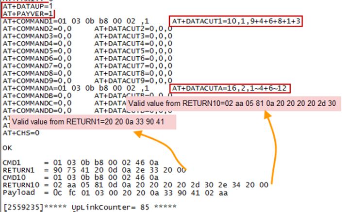
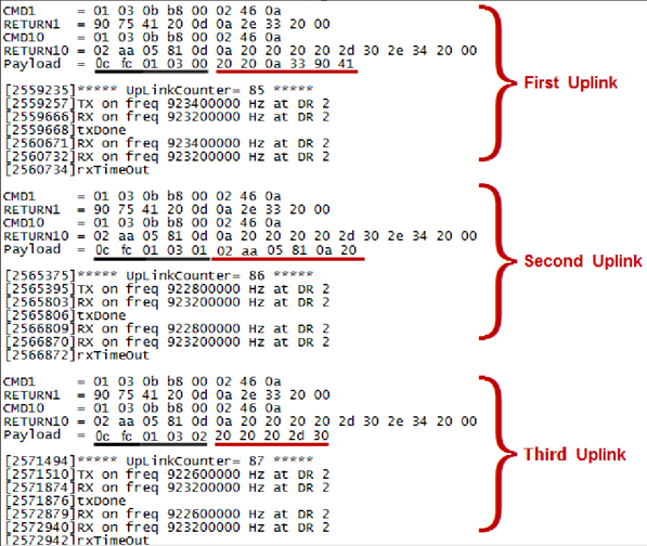
So totally there will be 3 uplinks for this sampling, each uplink includes 6 bytes DATA
DATA1=RETURN1 Valid Value = 20 20 0a 33 90 41
DATA2=1st ~ 6th byte of Valid value of RETURN10= 02 aa 05 81 0a 20
DATA3=7th ~ 11th bytes of Valid value of RETURN10 = 20 20 20 2d 30
Below are the uplink payloads:
Notice: the Max bytes is according to the max support bytes in different Frequency Bands for lowest SF. As below:
* For AU915/AS923 bands, if UplinkDwell time=0, max 51 bytes for each uplink ( so 51 -5 = 46 max valid date)
* For AU915/AS923 bands, if UplinkDwell time=1, max 11 bytes for each uplink ( so 11 -5 = 6 max valid date).
* For US915 band, max 11 bytes for each uplink ( so 11 -5 = 6 max valid date).
* For all other bands: max 51 bytes for each uplink ( so 51 -5 = 46 max valid date).
* When AT+DATAUP=1, the maximum number of segments is 15, and the maximum total number of bytes is 1500;
When AT+DATAUP=1 and AT+ADR=0, the maximum number of bytes of each payload is determined by the DR value. (Since v1.4.0)
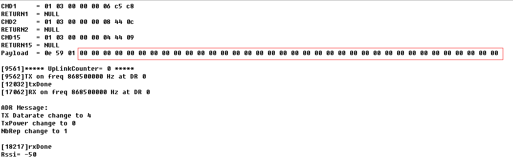
If the data is empty, return to the display(Since v1.4.0)
1) When AT+MOD=1, if the data intercepted by AT+DATACUT or AT+MBFUN is empty, it will display NULL, and the payload will be filled with n FFs.
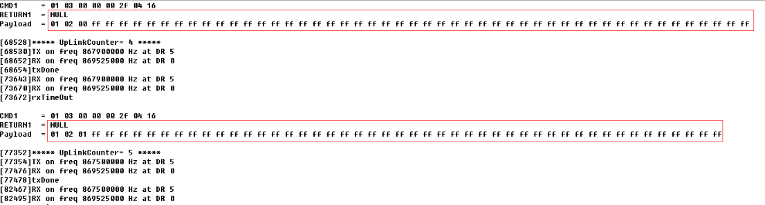
2) When AT+MOD=2, if the data intercepted by AT+DATACUT or AT+MBFUN is empty, it will display NULL, and the payload will be filled with n 00s.
3.3.5 Uplink on demand
Except uplink periodically, RS485-BL is able to uplink on demand. The server sends downlink command to RS485-BL and RS485 will uplink data base on the command.
Downlink control command:
0x08 command: Poll an uplink with current command set in RS485-BL.
0xA8 command: Send a command to RS485-BL and uplink the output from sensors.
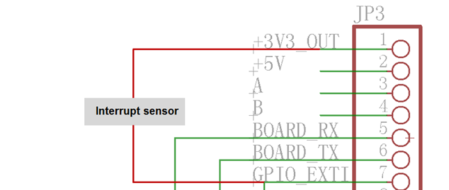
3.3.6 Uplink on Interrupt
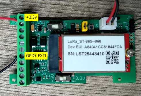
Put the interrupt sensor between 3.3v_out and GPIO ext.
AT+INTMOD=0 Disable Interrupt
AT+INTMOD=1 Interrupt trigger by rising or falling edge.
AT+INTMOD=2 Interrupt trigger by falling edge. (Default Value)
AT+INTMOD=3 Interrupt trigger by rising edge.
3.4 Uplink Payload
| Size(bytes) | 2 | 1 | Length depends on the return from the commands |
| Value | Battery(mV) & Interrupt _Flag | PAYLOAD_VER
| If the valid payload is too long and exceed the maximum support payload length in server, server will show payload not provided in the LoRaWAN server. |
Below is the decoder for the first 3 bytes. The rest bytes are dynamic depends on different RS485 sensors.
function Decoder(bytes, port) {//Payload Formats of RS485-BL Deceive
return {//Battery,units:V
BatV:((bytes[0]<<8 | bytes[1])&0x7fff)/1000,
//GPIO_EXTI
EXTI_Trigger:(bytes[0] & 0x80)? "TRUE":"FALSE",
//payload of version
Pay_ver:bytes[2],
};
}
TTN V3 uplink screen shot.

3.5 Configure RS485-BL via AT or Downlink
User can configure RS485-BL via AT Commands or LoRaWAN Downlink Commands
There are two kinds of Commands:
Common Commands: They should be available for each sensor, such as: change uplink interval, reset device. For firmware v1.3, user can find what common commands it supports: AT Commands and Downlink Command
Sensor Related Commands: These commands are special designed for RS485-BL. User can see these commands below:
3.5.1 Common Commands:
They should be available for each of Dragino Sensors, such as: change uplink interval, reset device. For firmware v1.3, user can find what common commands it supports: End Device AT Commands and Downlink Command
3.5.2 Sensor related commands:
Choose Device Type (RS485 or TTL) (Since v1.3.3)
RS485-BL can connect to either RS485 sensors or TTL sensor. User need to specify what type of sensor need to connect.
- AT Command
AT+MOD=1 // Set to support RS485-MODBUS type sensors. User can connect multiply RS485 , Modbus sensors to the A / B pins.
AT+MOD=2 // Set to support TTL Level sensors, User can connect one TTL Sensor to the TXD/RXD/GND pins.
- Downlink Payload
0A aa --> same as AT+MOD=aa
RS485 Debug Command (AT+CFGDEV)
This command is used to configure the RS485 or TTL sensors; they won't be used during sampling. Max Length of AT+CFGDEV is 40 bytes.
- AT Command
AT+CFGDEV=xx xx xx xx xx xx xx xx xx xx xx xx,m m: 0: no CRC; 1: add CRC-16/MODBUS in the end of this command.
Downlink Payload
Format: A8 MM NN XX XX XX XX YY
Where:
MM: 1: add CRC-16/MODBUS ; 0: no CRC
NN: The length of RS485 command
XX XX XX XX: RS485 command total NN bytes
YY: How many bytes will be uplink from the return of this RS485 command, if YY=0, RS485-BL will execute the downlink command without uplink; if YY>0, RS485-BL will uplink total YY bytes from the output of this RS485 command
Example 1:
To connect a Modbus Alarm with below commands.
The command to active alarm is: 0A 05 00 04 00 01 4C B0. Where 0A 05 00 04 00 01 is the Modbus command to read the register 00 40 where stored the DI status. The 4C B0 is the CRC-16/MODBUS which calculate manually.
The command to deactivate alarm is: 0A 05 00 04 00 00 8D 70. Where 0A 05 00 04 00 00 is the Modbus command to read the register 00 40 where stored the DI status. The 8D 70 is the CRC-16/MODBUS which calculate manually.
So if user want to use downlink command to control to RS485 Alarm, he can use:
A8 01 06 0A 05 00 04 00 01 00: to activate the RS485 Alarm
A8 01 06 0A 05 00 04 00 00 00: to deactivate the RS485 Alarm
A8 is type code and 01 means add CRC-16/MODBUS at the end, the 3rd byte is 06, means the next 6 bytes are the command to be sent to the RS485 network, the final byte 00 means this command don't need to acquire output.
Example 2:
Check TTL Sensor return:
Set Payload version
This is the first byte of the uplink payload. RS485-BL can connect to different sensors. User can set the PAYVER field to tell server how to decode the current payload.
- AT Command:
AT+PAYVER: Set PAYVER field = 1
- Downlink Payload:
0xAE 01 --> Set PAYVER field = 0x01
0xAE 0F --> Set PAYVER field = 0x0F
Set RS485 Sampling Commands
AT+COMMANDx, AT+DATACUTx and AT+SEARCHx
These three commands are used to configure how the RS485-BL polling data from Modbus device. Detail of usage please see : polling RS485 device.
AT Command:
AT+COMMANDx: Configure RS485 read command to sensor.
AT+DATACUTx: Configure how to handle return from RS485 devices.
AT+SEARCHx: Configure search command
Downlink Payload:
0xAF downlink command can be used to set AT+COMMANDx or AT+DATACUTx.
Note : if user use AT+COMMANDx to add a new command, he also need to send AT+DATACUTx downlink.
Format: AF MM NN LL XX XX XX XX YY
Where:
MM: the ATCOMMAND or AT+DATACUT to be set. Value from 01 ~ 0F,
NN: 0: no CRC; 1: add CRC-16/MODBUS ; 2: set the AT+DATACUT value.
LL: The length of AT+COMMAND or AT+DATACUT command
XX XX XX XX: AT+COMMAND or AT+DATACUT command
YY: If YY=0, RS485-BL will execute the downlink command without uplink; if YY=1, RS485-BL will execute an uplink after got this command.
Example:
AF 03 01 06 0A 05 00 04 00 01 00: Same as AT+COMMAND3=0A 05 00 04 00 01,1
AF 03 02 06 10 01 05 06 09 0A 00: Same as AT+DATACUT3=16,1,5+6+9+10
AF 03 02 06 0B 02 05 07 08 0A 00: Same as AT+DATACUT3=11,2,5~7+8~10
0xAB downlink command can be used for set AT+SEARCHx
Example: AB aa 01 03 xx xx xx (03 here means there are total 3 bytes after 03) So
AB aa 01 03 xx xx xx same as AT+SEARCHaa=1,xx xx xx
AB aa 02 03 xx xx xx 02 yy yy(03 means there are 3 bytes after 03, they are xx xx xx;02 means there are 2 bytes after 02, they are yy yy) so the commands
AB aa 02 03 xx xx xx 02 yy yy same as AT+SEARCHaa=2,xx xx xx+yy yy
Fast command to handle MODBUS device
AT+MBFUN is valid since v1.3 firmware version. The command is for fast configure to read Modbus devices. It is only valid for the devices which follow the MODBUS-RTU protocol.
This command is valid since v1.3 firmware version
AT+MBFUN has only two value:
AT+MBFUN=1: Enable Modbus reading. And get response base on the MODBUS return
AT+MBFUN=1, device can auto read the Modbus function code: 01, 02, 03 or 04. AT+MBFUN has lower priority vs AT+DATACUT command. If AT+DATACUT command is configured, AT+MBFUN will be ignore.
AT+MBFUN=0: Disable Modbus fast reading.
Example:
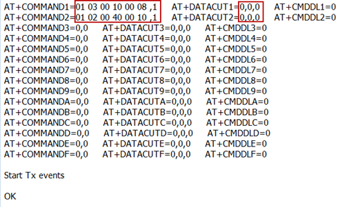
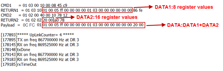
AT+MBFUN=1 and AT+DATACUT1/AT+DATACUT2 are not configure (0,0,0).
AT+COMMAND1= 01 03 00 10 00 08,1 --> read slave address 01 , function code 03, start address 00 01, quantity of registers 00 08.
AT+COMMAND2= 01 02 00 40 00 10,1 --> read slave address 01 , function code 02, start address 00 40, quantity of inputs 00 10.
Downlink Commands:
A9 aa --> Same as AT+MBFUN=aa
RS485 command timeout
Some Modbus device has slow action to send replies. This command is used to configure the RS485-BL to use longer time to wait for their action.
Default value: 0, range: 0 ~ 5 seconds
- AT Command:
AT+CMDDLaa=hex(bb cc)
Example:
AT+CMDDL1=1000 to send the open time to 1000ms
Downlink Payload:
0x AA aa bb cc Same as: AT+CMDDLaa=hex(bb cc)
Example:
0xAA 01 03 E8 --> Same as AT+CMDDL1=1000 ms
Uplink payload mode
Define to use one uplink or multiple uplinks for the sampling.
The use of this command please see: Compose Uplink payload
- AT Command:
AT+DATAUP=0
AT+DATAUP=1
AT+DATAUP=2 //The external sensor is sent as a separate packet and the data returned by the AT+COMMAND command is sent as a separate packet.
An asterisk ( * ) indicates that it is optional and can be added, refer to instructions AT+EXT=a,b,c to set up external sensors and pulse counts.
(FPORT2)Battery(mV) & Interrupt_Flag + PAYLOAD_VER + *SHT31 temp + *SHT31 Hum + *counting + *DS18B20
(FPORT3)PAYLOAD COUNT + PAYLOAD# + Length depends on the return from the commands
Note: AT+DATAUP=2 is only valid for the new firmware v1.4.5, which is not released, please contact us for testing.
Downlink Payload:
0xAD 00 --> Same as AT+DATAUP=0
0xAD 01 --> Same as AT+DATAUP=1 //Each uplink is sent to the server one after the other as it is segmented.
0xAD 02 --> Same as AT+DATAUP=2
- AT Command:
AT+DATAUP=1,Timeout
Downlink Payload:
0xAD 01 00 00 14 --> Same as AT+DATAUP=1,20000 //(00 00 14 is 20 seconds)
Each uplink is sent to the server at 20-second intervals when segmented.
Cut data separation processing(Since Version 1.4.2)
AT+NEWLINE command, which only takes effect when AT+DATAUP=1 or AT+DATAUP=1, timeout.
When not set, each part of AT+DATAUP is sent according to the maximum number of bytes of DR.
When setting, each part of AT+DATAUP is sent according to the value set by AT+NEWLINE.
AT Command:
AT+NEWLINE=ALL The data cut out by each AT+COMMANDx command is sent separately as an uplink.
AT+NEWLINE=ALL equal: AT+NEWLINE=1+2+3+4+5+6+7+8+9+10+11+12+13+14+15
AT+NEWLINE=a+b+c The data returned by all commands is divided into three parts, COMMAND(1~a) is the first part, COMMAND(a+1~b) is the second part,COMMAND(b+1~c) is the third part.
AT+NEWLINE=NULL Turn off the functionality of this AT command.
Downlink Payload:
AT+NEWLINE=ALL ---> 0xAC 01
AT+NEWLINE= NULL ---> 0xAC 00
AT+NEWLINE= a+b+c ---> 0xAC number of bytes a b c
AT+NEWLINE= 1+5+15 ---> 0xAC 03 01 05 0F
Manually trigger an Uplink
Ask device to send an uplink immediately.
- Downlink Payload:
0x08 FF, RS485-BL will immediately send an uplink.
Clear RS485 Command
The AT+COMMANDx and AT+DATACUTx settings are stored in special location, user can use below command to clear them.
AT Command:
AT+CMDEAR=mm,nn mm: start position of erase ,nn: stop position of erase Etc. AT+CMDEAR=1,10 means erase AT+COMMAND1/AT+DATACUT1 to AT+COMMAND10/AT+DATACUT10
Example screen shot after clear all RS485 commands.
The uplink screen shot is:
Downlink Payload:
0x09 aa bb same as AT+CMDEAR=aa,bb
Set Serial Communication Parameters
Set the Rs485 serial communication parameters:
AT Command:
- Set Baud Rate:
AT+BAUDR=9600 // Options: (200~115200),When using low baud rate or receiving multiple bytes, you need to use AT+CMDDL to increase the receive timeout (the default receive timeout is 300ms), otherwise data will be lost
- Set UART Parity
AT+PARITY=0 // Option: 0: no parity, 1: odd parity, 2: even parity
- Set STOPBIT
AT+STOPBIT=0 // Option: 0 for 1bit; 1 for 1.5 bit ; 2 for 2 bits
Downlink Payload:
A7 01 aa bb: Same AT+BAUDR=hex(aa bb)*100
Example:
A7 01 00 60 same as AT+BAUDR=9600
A7 01 04 80 same as AT+BAUDR=115200
A7 02 aa: Same as AT+PARITY=aa (aa value: 00, 01 or 02)
A7 03 aa: Same as AT+STOPBIT=aa (aa value: 00, 01 or 02)
Configure Databit(Since version 1.4.0)
AT Command:
AT+DATABIT=7 // Set the data bits to 7
AT+DATABIT=8 //Set the data bits to 8
Downlink Payload:
A7 04 07: Same as AT+DATABIT=7
A7 04 08: Same as AT+DATABIT=8
Encrypted payload
AT Command:
AT+DECRYPT=1 // The payload is uploaded without encryption
AT+DECRYPT=0 // Encrypt when uploading payload (default)
Get sensor value
AT Command:
AT+GETSENSORVALUE=0 // The serial port gets the reading of the current sensor
AT+GETSENSORVALUE=1 // The serial port gets the current sensor reading and uploads it.
Resets the downlink packet count
AT Command:
AT+DISFCNTCHECK=0 // When the downlink packet count sent by the server is less than the node downlink packet count or exceeds 16384, the node will no longer receive downlink packets (default)
AT+DISFCNTCHECK=1 // When the downlink packet count sent by the server is less than the node downlink packet count or exceeds 16384, the node resets the downlink packet count and keeps it consistent with the server downlink packet count.
When the limit bytes are exceeded, upload in batches
AT Command:
AT+DISMACANS=0 // When the MACANS of the reply server plus the payload exceeds the maximum number of bytes of 11 bytes (DR0 of US915, DR2 of AS923, DR2 of AU195), the node will send a packet with a payload of 00 and a port of 4. (default)
AT+DISMACANS=1 // When the MACANS of the reply server plus the payload exceeds the maximum number of bytes of the DR, the node will ignore the MACANS and not reply, and only upload the payload part.
Downlink Payload
0x21 00 01 // Set the DISMACANS=1
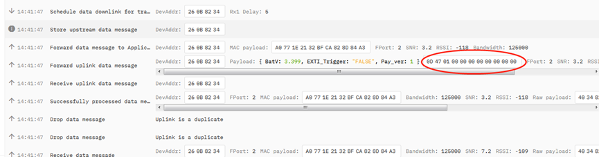
Copy downlink to uplink
AT Command:
AT+RPL=5 // After receiving the package from the server, it will immediately upload the content of the package to the server, the port number is 100.
Example:aa xx xx xx xx // aa indicates whether the configuration has changed, 00 is yes, 01 is no; xx xx xx xx are the bytes sent.
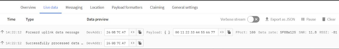
For example, sending 11 22 33 44 55 66 77 will return invalid configuration 00 11 22 33 44 55 66 77.
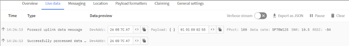
For example, if 01 00 02 58 is issued, a valid configuration of 01 01 00 02 58 will be returned.
Query version number and frequency band 、TDC
Downlink Payload: 26 01 // Downlink 26 01 can query device upload frequency, frequency band, software version number, TDC time.
Example:

Control output power duration
Before v1.4.4, the maximum settable time of 3V3T and 5VT is 65535 milliseconds. After v1.4.4, the maximum settable time of 3V3T and 5VT is 180 seconds.
User can set the output power duration before each sampling.
AT Command:
Example:
AT+3V3T=1000 // 3V3 output power will open 1s before each sampling.
AT+5VT=1000 // +5V output power will open 1s before each sampling.
LoRaWAN Downlink Command:
Example:
When the delay is less than 65 seconds, Downlink can be controlled by 4 bytes or 5 bytes:
07 01 aa bb Same as AT+5VT=(aa<<8 | bb)
07 02 aa bb Same as AT+3V3T=(aa<<8 | bb)
07 01 aa bb cc Same as AT+5VT=(aa<<16 | bb<<8 | cc)
07 02 aa bb cc Same as AT+3V3T=(aa<<16 | bb<<8 | cc)
When the delay is greater than 65 seconds, the Downlink is controlled by 5 bytes:
07 01 aa bb cc Same as AT+5VT=(aa<<16 | bb<<8 | cc)
07 02 aa bb cc Same as AT+3V3T=(aa<<16 | bb<<8 | cc)
3.6 Connect to external temperature sensor & counting sensor
Note: This feature is only available for new unreleased firmware v1.4.5, please contact us for testing.
- AT Command:
AT+EXT=a,b,c
a: 0: ignore I2C interface. 1: Add SHT31 sensor support (4 bytes).
b: 0: ignore pulse interface ( doesn't effect interrupt ). 1: Add Counting Support (4 bytes).
c: 0: ignore one wire interface. 1: add DS18B20 support (2 bytes).
Example:
AT+EXT=1,1,1
Device will add SHT31, counting, DS18B20 support.
The payload will be:
Battery(mV) & Interrupt _Flag + PAYLOAD_VER + *SHT31 temp + *SHT31 Hum + *counting + *DS18B20 + Length depends on the return from the commands
AT+EXT=0,1,0
Device will add counting support.
The payload will be:
Battery(mV) & Interrupt _Flag + PAYLOAD_VER + *counting + Length depends on the return from the commands
- AT Command:
AT+SETCNT=aa //Set the pulse count value.
Example:
AT+SETCNT=0 //Set the pulse count to 0.
Connect DS18B20 sensor
RED <---------> +3.3V
YELLOW <----> ONE_WIRE
BLACK <------> GND
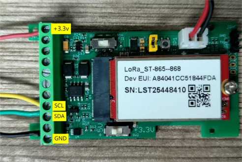
Connect SHT31 sensor
RED <---------> +3.3V
YELLOW <----> SCL
GREEN <------> SDA
BLACK <------> GND
Connect counting sensor
The counting sensor cables are connected to the +3.3v pin and GPIO_EXTI pin of the RS485_BL motherboard.
3.7 Buttons
| Button | Feature |
|---|---|
| RST | Reboot RS485-BL |
3.8 +3V3 Output (Since v1.3.3)
RS485-BL has a Controllable +3V3 output, user can use this output to power external sensor.
The +3V3 output will be valid for every sampling. RS485-BL will enable +3V3 output before all sampling and disable the +3V3 after all sampling.
The +3V3 output time can be controlled by AT Command.
AT+3V3T=1000
Means set +3v3 valid time to have 1000ms. So, the real +3v3 output will actually have 1000ms + sampling time for other sensors.
By default, the AT+3V3T=0. This is a special case, means the +3V3 output is always on at any time
3.9 +5V Output (Since v1.3.3)
RS485-BL has a Controllable +5V output, user can use this output to power external sensor.
The +5V output will be valid for every sampling. RS485-BL will enable +5V output before all sampling and disable the +5v after all sampling.
The 5V output time can be controlled by AT Command.
(AT+5VT increased from the maximum 5000ms to 65000ms.Since v1.4.0)
AT+5VT=1000
Means set 5V valid time to have 1000ms. So, the real 5V output will actually have 1000ms + sampling time for other sensors.
By default, the AT+5VT=0. If the external sensor which require 5v and require more time to get stable state, user can use this command to increase the power ON duration for this sensor.
3.10 LEDs
| LEDs | Feature |
|---|---|
| LED1 | Blink when device transmit a packet. |
3.11 Switch Jumper
| Switch Jumper | Feature |
|---|---|
| SW1 | ISP position: Upgrade firmware via UART Flash position: Configure device, check running status. |
| SW2 | 5V position: set to compatible with 5v I/O. 3.3v position: set to compatible with 3.3v I/O., |
+3.3V: is always ON
+5V: Only open before every sampling. The time is by default, it is AT+5VT=0. Max open time. 65000 ms.(Since v1.4.0)
3.12 Battery & Power Consumption
RS485-BL uses ER26500 + SPC1520 battery pack. See below link for detail information about the battery info and how to replace.
Battery Info & Power Consumption Analyze .
4. Case Study
User can check this URL for some case studies: APP RS485 COMMUNICATE WITH SENSORS
5. Use AT Command
5.1 Access AT Command
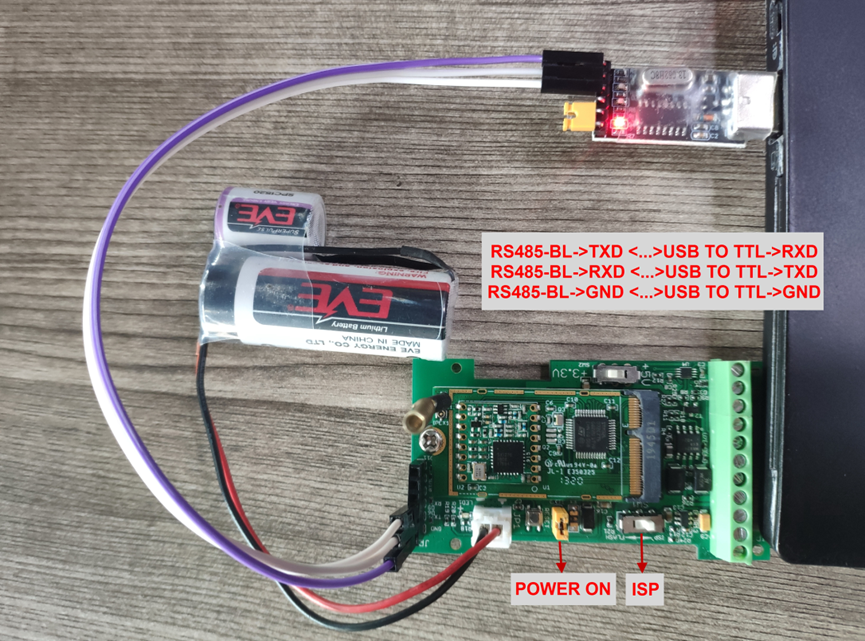
RS485-BL supports AT Command set. User can use a USB to TTL adapter plus the 3.5mm Program Cable to connect to RS485-BL to use AT command, as below.
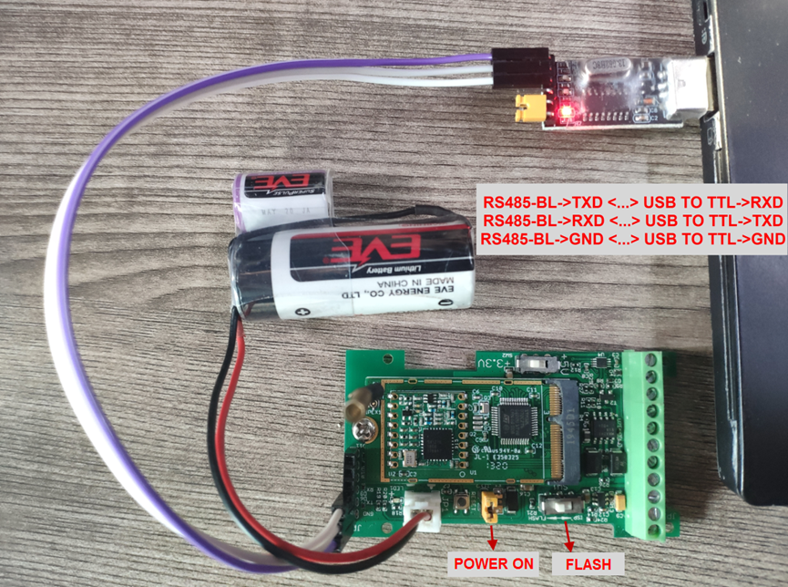
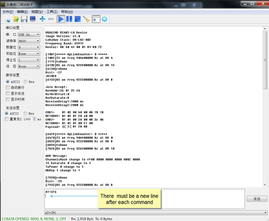
In PC, User needs to set serial tool(such as putty, SecureCRT) baud rate to 9600 to access to access serial console of RS485-BL. The default password is 123456. Below is the output for reference:
More detail AT Command manual can be found at AT Command Manual
5.2 Common AT Command Sequence
5.2.1 Multi-channel ABP mode (Use with SX1301/LG308)
If device has not joined network yet:
- AT+FDR
- AT+NJM=0
- ATZ
If device already joined network:
- AT+NJM=0
- ATZ
5.5.2 Single-channel ABP mode (Use with LG01/LG02)
AT+FDR Reset Parameters to Factory Default, Keys Reserve
AT+NJM=0 Set to ABP mode
AT+ADR=0 Set the Adaptive Data Rate Off
AT+DR=5 Set Data Rate
AT+TDC=60000 Set transmit interval to 60 seconds
AT+CHS=868400000 Set transmit frequency to 868.4Mhz
AT+RX2FQ=868400000 Set RX2Frequency to 868.4Mhz (according to the result from server)
AT+RX2DR=5 Set RX2DR to match the downlink DR from server. see below
AT+DADDR=26 01 1A F1 Set Device Address to 26 01 1A F1, this ID can be found in the LoRa Server portal.
ATZ Reset MCU
Note:
1. Make sure the device is set to ABP mode in the IoT Server.
2. Make sure the LG01/02 gateway RX frequency is exactly the same as AT+CHS setting.
3. Make sure SF / bandwidth setting in LG01/LG02 match the settings of AT+DR. refer this link to see what DR means.
4. The command AT+RX2FQ and AT+RX2DR is to let downlink work. to set the correct parameters, user can check the actually downlink parameters to be used. As below. Which shows the RX2FQ should use 868400000 and RX2DR should be 5
6. FAQ
6.1 How to upgrade the image?
The RS485-BL LoRaWAN Controller is shipped with a 3.5mm cable, the cable is used to upload image to RS485-BL to:
Support new features
For bug fix
Change LoRaWAN bands.
Below shows the hardware connection for how to upload an image to RS485-BL:
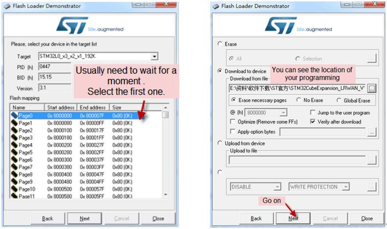
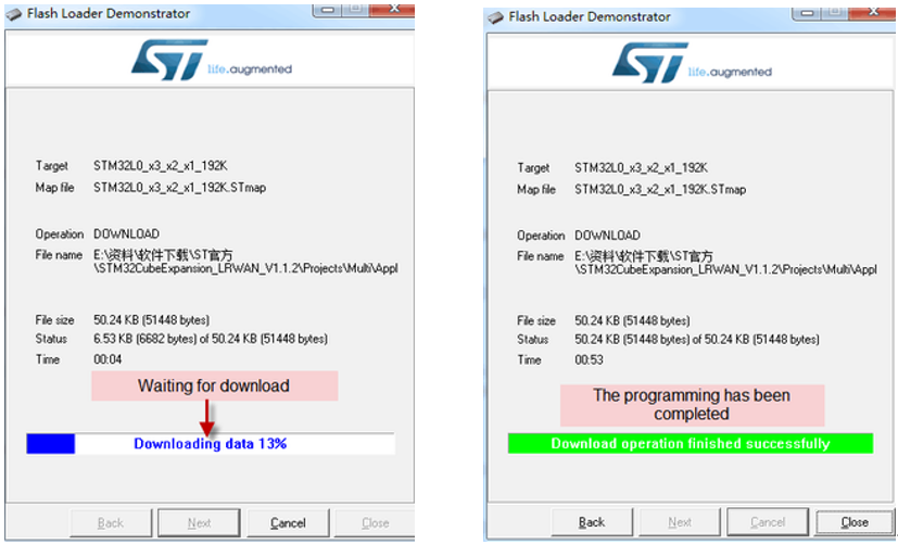
Step1: Download flash loader.
Step2: Download the LT Image files.
Step3: Open flashloader; choose the correct COM port to update.

6.2 How to change the LoRa Frequency Bands/Region?
User can follow the introduction for how to upgrade image. When download the images, choose the required image file for download.
6.3 How many RS485-Slave can RS485-BL connects?
The RS485-BL can support max 32 RS485 devices. Each uplink command of RS485-BL can support max 16 different RS485 command. So RS485-BL can support max 16 RS485 devices pre-program in the device for uplink. For other devices no pre-program, user can use the downlink message (type code 0xA8) to poll their info.
6.4 How to Use RS485-BL to connect to RS232 devices?
Use RS485-BL or RS485-LN to connect to RS232 devices. - DRAGINO
6.5 How to judge whether there is a problem with the set COMMAND
6.5.1 Introduce:
Users can use below the structure to fast debug the communication between RS485BL and RS485-LN. The principle is to put the PC in the RS485 network and sniff the packet between Modbus MTU and RS485-BL/LN. We can use this way to:
- Test if Modbus-MTU works with PC commands.
- Check if RS485-LN sent the expected command to Mobus-MTU
- Check if Modbus-MTU return back the expected result to RS485-LN.
- If both b) and c) has issue, we can compare PC’s output and RS485-LN output.
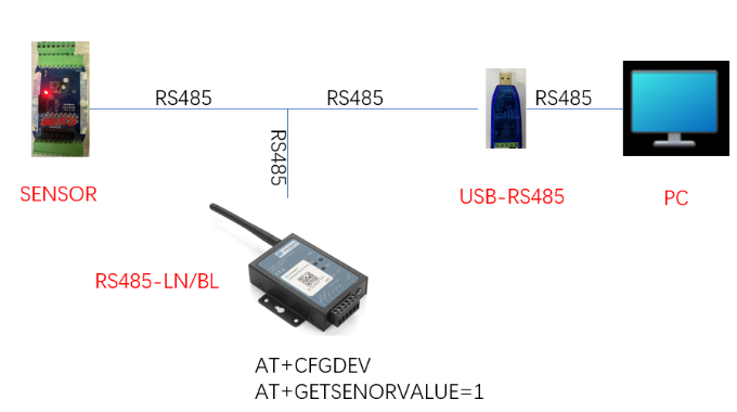
Example Connection:
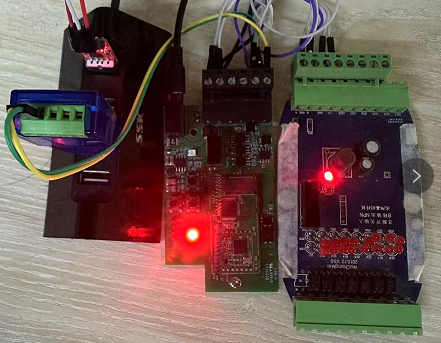
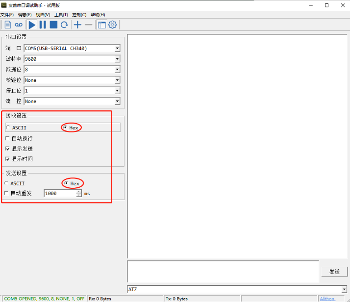
6.5.2 Set up PC to monitor RS485 network With Serial tool
Note: Receive and send set to hex mode
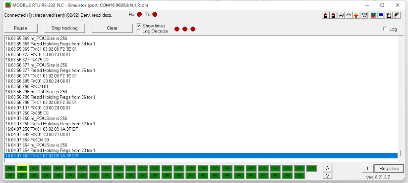
6.5.3 With ModRSsim2:
(1) Select serial port MODBUS RS-232
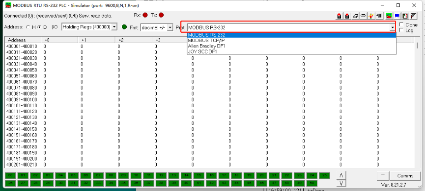
(2) Click the serial port icon
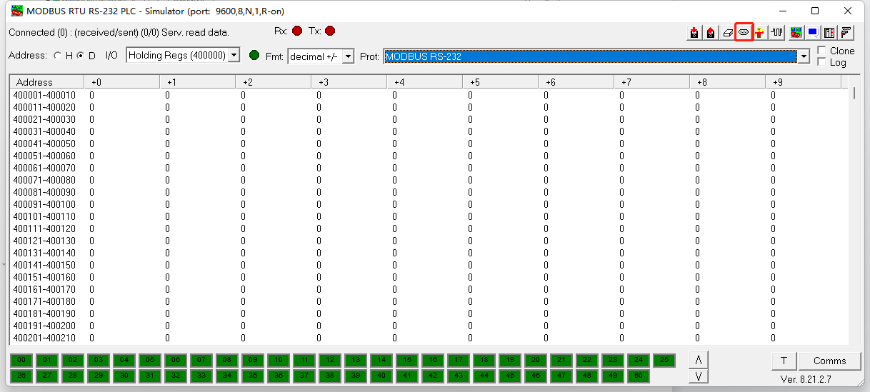
(3) After selecting the correct serial port and baud rate, click ok
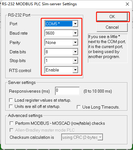
(4) Click the comms.
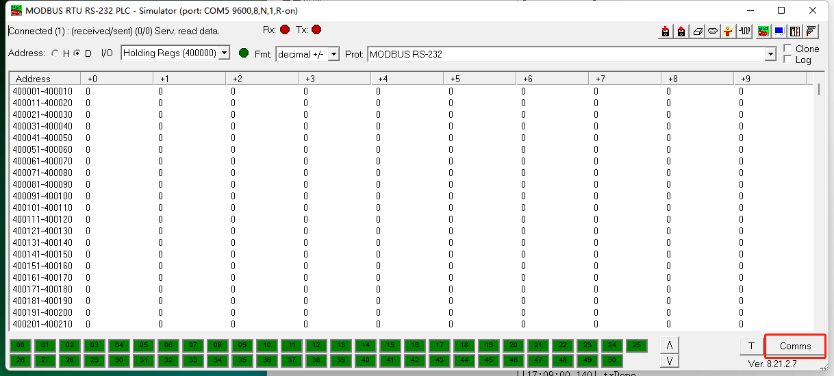
Run RS485-LN/BL command and monitor if it is correct.
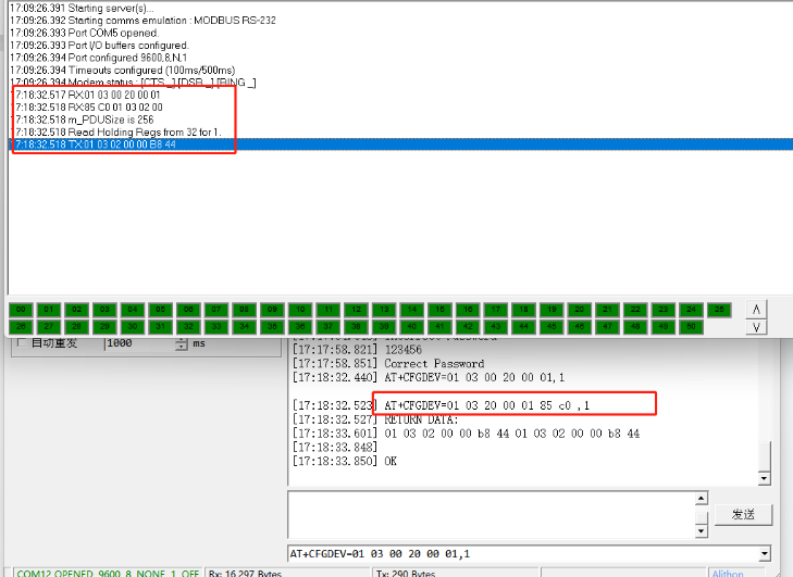
6.5.4 Example – Test the CFGDEV command
RS485-LN sent below command:
AT+CFGDEV=01 03 20 00 01 85 c0,1 to RS485 network, and PC is able to get this command and return commands from MTU to show in the serial tool.
We can see the output from the Serial port tool to analyze. And check if they are expected result.
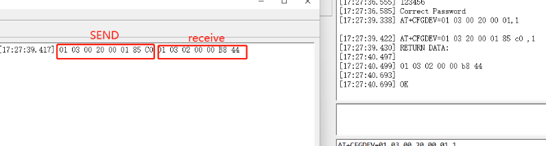
We can also use ModRSsim2 to see the output.
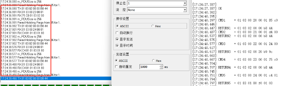
6.5.5 Example – Test CMD command sets.
Run AT+SENSORVALUE=1 to test the CMD commands set in RS485-LN.
Serial port tool:
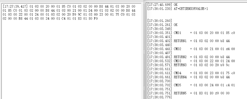
ModRSsim2:
6.5.6 Test with PC
If there is still have problem to set up correctly the commands between RS485-LN and MTU. User can test the correct RS485 command set in PC and compare with the RS485 command sent out via RS485-LN. as long as both commands are the same, the MTU should return correct result.
Or User can send the working commands set in PC serial tool to Dragino Support to check what should be configured in RS485-LN.
Connection method:

Link situation:
6.6 Where to get the decoder for RS485-BL?
The decoder for RS485-BL needs to be written by yourself. Because the sensor to which the user is connected is custom, the read device data bytes also need custom parsing, so there is no universal decoder. We can only provide templates for decoders (no intermediate data parsing part involved)
6.7 Why does my TTL sensor have returned data, but after using the command AT+DATACUT, the data in the payload is 0?
In TTL mode, you cannot use the node to automatically calculate the check code, you need to manually add the check code.
6.8 Where can I get a decoder?
Provides two decoders:
dragino-end-node-decoder/RS485-BL at main · dragino/dragino-end-node-decoder (github.com)
https://github.com/zorbaproject/ArduinoModbusForDraginoRS485#payload-decoder-for-thethingsnetwork
6.9 How to configure RS485 commands more conveniently?
Dragino has developed an application for the RS485 series of products.
It can help you configure RS485 sensors more conveniently
Please refer to the link below for specific usage:
RS485 Configure Tool - DRAGINO
7. Trouble Shooting
7.1 Downlink doesn't work, how to solve it?
Please see this link for debug: LoRaWAN Communication Debug
7.2 Why I can't join TTN V3 in US915 /AU915 bands?
It might about the channels mapping. Please see for detail: Notice of Frequency band
7.3 Possible reasons why the device is unresponsive:
1. Check whether the battery voltage is lower than 2.8V
2. Check whether the jumper of the device is correctly connected
3. Check whether the switch here of the device is at the ISP(The switch can operate normally only when it is in RUN)
8. Order Info
Part Number: RS485-BL-XXX
XXX:
- EU433: frequency bands EU433
- EU868: frequency bands EU868
- KR920: frequency bands KR920
- CN470: frequency bands CN470
- AS923: frequency bands AS923
- AU915: frequency bands AU915
- US915: frequency bands US915
- IN865: frequency bands IN865
- RU864: frequency bands RU864
- KZ865: frequency bands KZ865
9. Packing Info
Package Includes:
RS485-BL x 1
Stick Antenna for LoRa RF part x 1
Program cable x 1
Dimension and weight:
Device Size: 13.5 x 7 x 3 cm
Device Weight: 105g
Package Size / pcs : 14.5 x 8 x 5 cm
Weight / pcs : 170g
10. Support
Support is provided Monday to Friday, from 09:00 to 18:00 GMT+8. Due to different timezones we cannot offer live support. However, your questions will be answered as soon as possible in the before-mentioned schedule.
Provide as much information as possible regarding your enquiry (product models, accurately describe your problem and steps to replicate it etc) and send a mail to support@dragino.com