NDS01 - NB-IoT Door Sensor User Manual
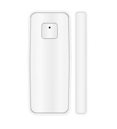
Table of Contents:
- 1. Introduction
- 2. Use NDS01 to communicate with IoT Server
- 3. FAQ
- 4. Order Info
- 5. Packing Info
- 6. Support
1. Introduction
1.1 What is NDS01 NB-IoT Door Sensor
The Dragino NDS01 is a NB-IOT Door Sensor for Internet of Things solution. It is used to detect the open/close event for door and uplink the event to IoT server via NB-IoT network.
Besides open/close event, NDS01 also has an internal temperature and humidity sensor which can detect the temperature and humidity inside the sensor.
NarrowBand-Internet of Things (NB-IoT) is a standards-based low power wide area (LPWA) technology developed to enable a wide range of new IoT devices and services. NB-IoT significantly improves the power consumption of user devices, system capacity and spectrum efficiency, especially in deep coverage.
NDS01 is powered by 2 x AAA batteries for long term use.
*The measured temperature is 2~3 degree higher than the actually environment temperature out of NDS01.

1.2 Specifications
Common DC Characteristics:
- Supply Voltage: 2.1v ~ 3.6v
- Operating Temperature: -10 ~ 50°C
NB-IoT Spec:
- B1 @H-FDD: 2100MHz
- B3 @H-FDD: 1800MHz
- B8 @H-FDD: 900MHz
- B5 @H-FDD: 850MHz
- B20 @H-FDD: 800MHz
- B28 @H-FDD: 700MHz
Power Consumption
- IDEL Mode: 10uA @ 3.3v
- Max transmit power: <500mA@3.3v
1.3 Features
- NB-IoT Bands: B1/B3/B5/B8/B20/B28 @H-FDD
- Ultra low power consumption
- Door Open / Close Detect
- Device remove alarm
- Uplink Protocol: TCP or UDP
- Uplink on periodically
- Micro SIM card slot for NB-IoT SIM
- 2 x AAA LR03 Batteries
1.4 Applications
- Smart Buildings & Home Automation
- Logistics and Supply Chain Management
- Smart Cities
- Smart Factory
2. Use NDS01 to communicate with IoT Server
2.1 How it works
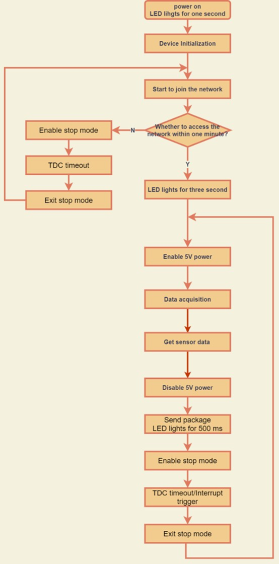
The NDS01 is equipped with a NB-IoT module, the pre-loaded firmware in NDS01 will get environment data from sensors and send the value to local NB-IoT network via the NB-IoT module. The NB-IoT network will forward this value to IoT server via the protocol defined by NDS01.
The diagram below shows the working flow in default firmware of NDS01:
2.2 Configure the NDS01
2.2.1 Test Requirement
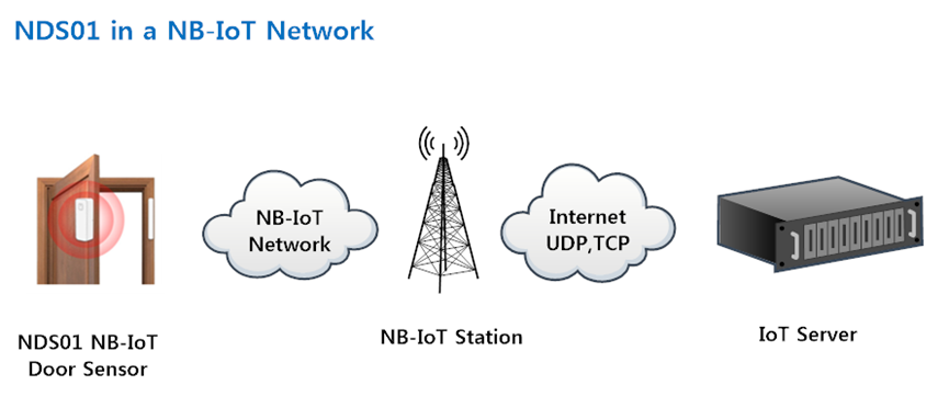
To use NDS01 in your city, make sure meet below requirements:
- Your local operator has already distributed a NB-IoT Network there.
- The local NB-IoT network used the band that NDS01 supports.
- Your operator is able to distribute the data received in their NB-IoT network to your IoT server.
Below figure shows our testing structure.Here we have NB-IoT network coverage by China Mobile, the band they use is B8. The NDS01 will use UDP(120.24.4.116:5601) or TCP(120.24.4.116:5600) protocol to send data to IoT server.
2.2.2 Insert SIM card
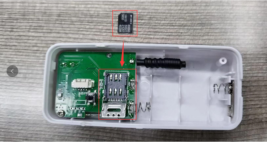
Insert the NB-IoT Card get from your provider.
User need to take out the NB-IoT module and insert the SIM card like below:
2.2.3 Configure NDS01
User need to configure NDS01 via serial port to set the Server Address / Uplink Topic to define where and how-to uplink packets. NDS01 support AT Commands, user can use a USB to TTL adapter to connect to NDS01 and use AT Commands to configure it, NDS01 needs to be in the wake-up state when using AT commands,as below.
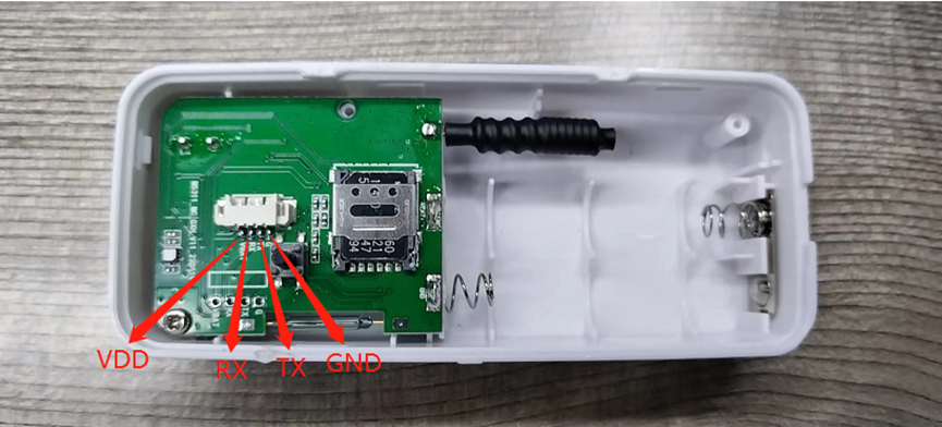
Connection:
USB TTL GND <----> GND
USB TTL TXD <----> UART_RXD
USB TTL RXD <----> UART_TXD
In the PC, use below serial tool settings:
- Baud: 115200
- Data bits: 8
- Stop bits: 1
- Parity: None
- Flow Control: None
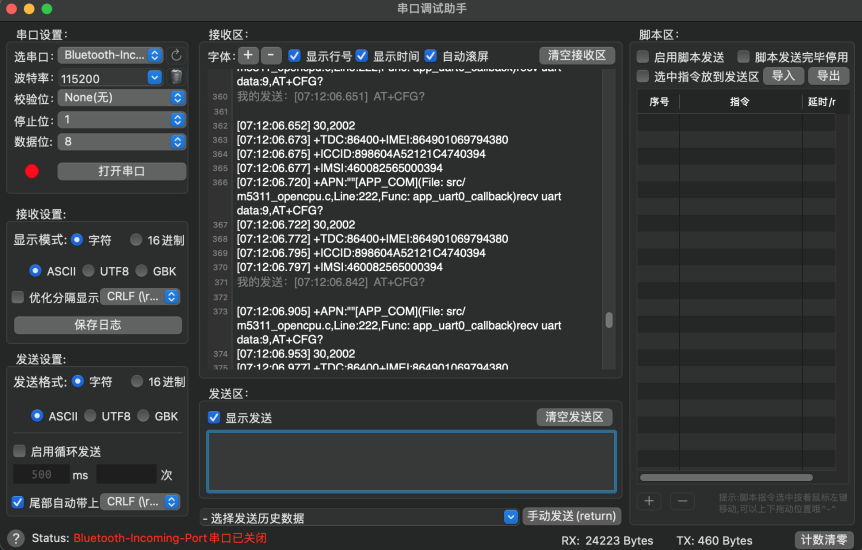
If you are using Mac OS, please download the serial port assistant for Mac OS. The settings and operation are the same as Windows
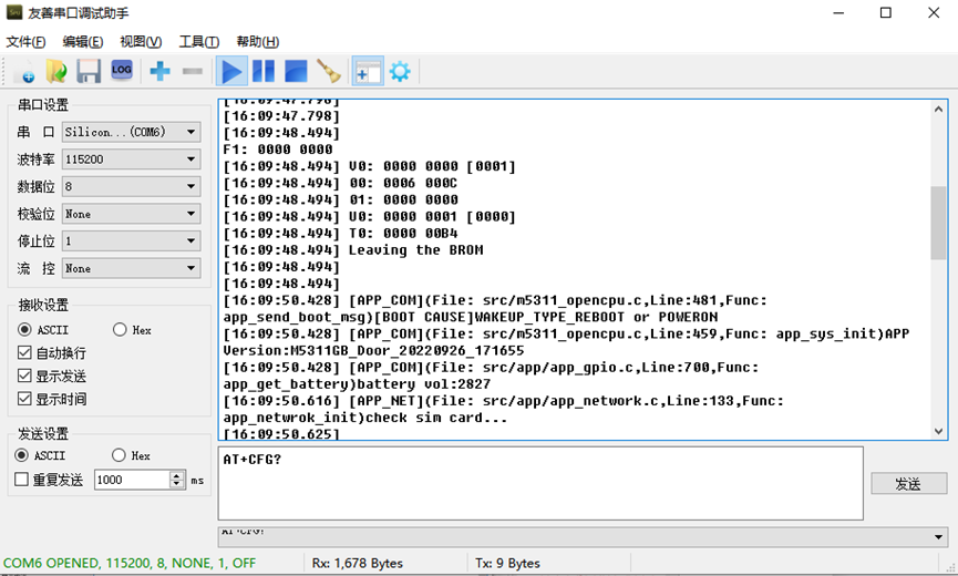
After powering on the NDS01, the following information will be printed
AT command set
1. Set and query the communication protocol
Send: AT+PRO=<val> Val: 0:TCP 1:UDP
Reply: OK
Send: AT+PRO? // Inquire
Reply: +PRO:0
OK
2. Set and query the server address
Send: AT+SERVADDR=<server>,<port>
Reply: OK
Send: AT+SERVADDR? // Inquire
Reply: +SERVADDR:<server>,<port>
OK
3. Set and query the TDC
Send: AT+TDC=<value> // Heartbeat time, in seconds, the default is 86400s,which is 24 hours
Reply: OK
Send: AT+TDC? // Inquire
Reply: +TDC:<value>
OK
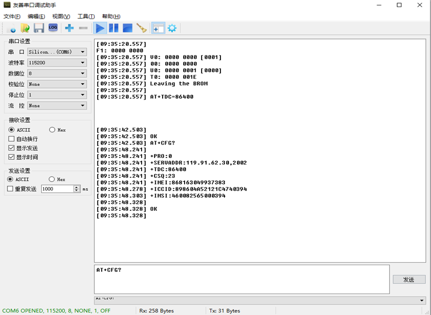
4. Query parameters
Send: AT+CFG?
Reply: +PRO:0
+SERVADDR:120.27.12.119,2023
+TDC:86400
+CSQ:31
+IMEI:868163049937383
+ICCID:898604611619C0854626
+IMSI:460048118204626
OK
5. Set and query the APN
Send: AT+APN="<apn>" // Set APN
Reply: OK
Send: AT+APN? // Inquire
Reply: +APN:"cmiot"
OK
6. Alarm and Silencer
Send: AT+ALARM=<value> // 0~1,0: mute 1: buzzer alarm (note that no data will be reported, only the buzzer and the red light are on, if it is in silent mode, only the red light is on)
Reply: OK
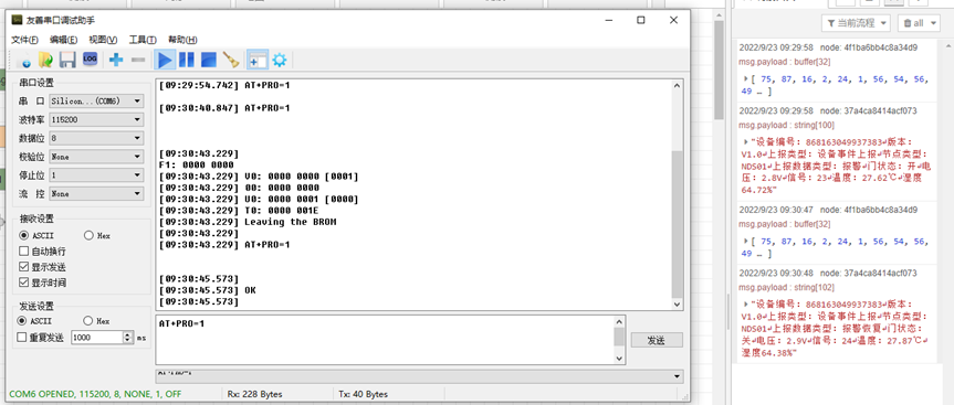
2.2.4 Use UDP protocol to uplink data (Default protocol)
- AT+PRO=1 // Set to use UDP protocol to uplink
- AT+SERVADDR=119.91.62.30,1999 // to set UDP server address and port
2.2.5 Use TCP protocol to uplink data
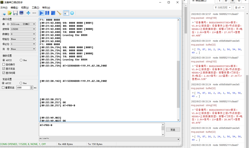
- AT+PRO=0 // Set to use TCP protocol to uplink
- AT+SERVADDR=119.91.62.30,2002 // to set TCP server address and port
2.2.6 Change Update Interval
User can use below command to change the uplink interval.
- AT+TDC=86400 // Set Update Interval to 86400s
NOTE:
1. By default, the device will send an uplink message every 24 hour (86400s).
2.3 Uplink Payload
registration package, uplink payload includes in total 61 bytes
Size(bytes) | 2 | 1 | 1 | 1 | 1 | 15 | 15 | 20 | 1 | 1 | 3 |
| Value | head | Version | data type | Data length | device type | device ID | IMSI | ICCID | BAT | Signal | tail |
The payload is ASCII string, representative same HEX: 0x 4B57 10 01 34 01 383639393735303334343431303832 3839383631313230323234303134333938373632 1E 15 494F54
where:
- Head: 0x4B57(fixed)
- Version: 0x10=”V1.0”
- Data type: 0x01=1(1:register,2:data sending)
- Data length: 0x34=52(Valid data is 52 bytes)
- Device type: 0x01 = 1(Representative NDS01)
- Device ID: 0x383639393735303334343431303832=869975034441082(ASCII)
- IMSI: 0x343630313133313138373433373332 = 460113118743732(ASCII)
- ICCID: 0x3839383631313230323234303134333938373632=89861120224014398762(ASCII)
- Bat: 0x1E = 30/10=3.0V
- Signal: 0x15=21
0 -113dBm or less
1 -111dBm
2...30 -109dBm... -53dBm
31 -51dBm or greater
99 Not known or not detectable
- Tail: 0x494F54(fixed)
data upload, uplink payload includes in total 32 bytes
Size(bytes) | 2 | 1 | 1 | 1 | 1 | 15 | 1 |
| Value | head | Version | data type | Data length | device type | device ID | event type |
| 1 | 1 | 1 | 1 | 1 | 1 | 1 | 3 |
| Door magnetic state | BAT | Signal | Temp integer | Temp decimal | Hum integer | Hum decimal | tail |
The payload is ASCII string, representative same HEX: 0x 4B57 10 02 14 01 383639393735303334343431303832 01 00 20 15 1c 55 23 12 454F54
where:
- Head: 0x4B57(fixed)
- Version: 0x10=”V1.0”
- Data type: 0x02=2(1:register,2:data sending)
- Data length: 0x14=20(Valid data is 20 bytes)
- Device type: 0x01 = 1(Representative NDS01)
- Device ID: 0x383639393735303334343431303832=869975034441082(ASCII)
- Event type: 0x01
01: TDC
02: alarm
03: remove alarm
04: dismantling alarm
05: remove demolition alarm
06: low voltage
07: remove low voltage
- Door magnetic state: 0x00
00: Door sensor is close
01: Door sensor is open
- Bat: 0x20 = 32/10=3.2V
- Signal: 0x15=21
0 -113dBm or less
1 -111dBm
2...30 -109dBm... -53dBm
31 -51dBm or greater
99 Not known or not detectable
- Temp integer: 0x1c=28
- Temp decimal: 0x55=85
Temp =Temp integer+(Temp decimal)/100=28+85/100=28.85℃
- Hum integer: 0x23=35
- Hum decimal: 0x12=18
Hum =Hum integer+(Hum decimal)/100=35+18/100=35.18%rh
- Tail: 0x494F54(fixed)
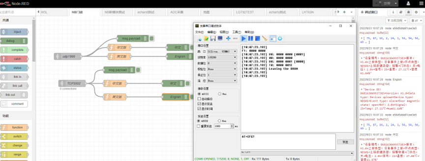
2.4 Node-Red Example
Please refer to this link for the use of Node-RED: http://wiki.dragino.com/xwiki/bin/view/Main/Node-RED/
Please visit this link to download the Node-RED process: https://github.com/dragino/dragino-end-node-decoder/tree/main/Node-RED
2.5 Buttons and LED and Mode
Operating mode
(1) In the self-check mode (the default is the self-check mode when power on for the first time), the state change of the tamper switch does not trigger an alarm;
(2) In normal working mode, the state change of the tamper switch triggers an alarm;
(3) In silent mode (the default is non-silent mode when power on for the first time), the buzzer is silent.
led lights
(1) After the device is powered on, the green light flashes once;
(2) The device does not set server parameters or cannot connect to the server, and the green light flashes quickly;
(3) SIM card recognition fails, the green light is always on for 20s;
(4) The equipment signal is poor, and the green light flashes once every 3 seconds;
(5) When the device sends data, the green light flashes twice;
(6) The communication of the equipment is normal, and the green light flashes 3 times continuously;
(7) Trigger the tamper switch, the red light is always on for 30s, and goes out when the alarm is canceled;
(8) Trigger the door magnetic alarm, the red light is always on for 30s, and goes out when the alarm is canceled;
buzzer
(1) When the door magnetic alarm is triggered, the buzzer will sound for 30s; after the alarm is restored, the buzzer will be silenced;
(2) Enter the normal working mode (the tamper switch is closed for more than 5s or the door sensor is locked for more than 5s), the buzzer will sound for 1500ms;
(3) After entering the normal working mode, the tamper switch does not close, the buzzer sounds for 30s, the tamper switch is closed, and the buzzer sounds 1 time;
(4) When the door sensor does not alarm, press the button to trigger the alarm, and the buzzer will sound for 30s; when the door sensor alarms, press it once to cancel the alarm, and the buzzer will be silenced.
button
(1) When there is no alarm, press it once to trigger the alarm, and the buzzer will sound; when it alarms, press the buzzer to silence the sound.
(2) Press twice to silence the buzzer;
(3) Press the button three times or more, when the mute function is turned off, the mute function is turned on, and the green light flashes once; when the mute function is turned on, the mute function is turned off, and the green light flashes once.
data pack
(1) The device needs to send a registration packet and a heartbeat packet every time it is powered on and registered;
(2) The heartbeat time is reported once every 24 hours by default.
3. FAQ
3.1 How to Upgrade Firmware
User can upgrade the firmware for 1) bug fix, 2) new feature release.
Burning software please go to this link to download: https://www.dropbox.com/sh/floxy4qsf2rgnrc/AAAJXz_rex37dPHwqVMBaqI_a?dl=0
Note:
Disconnect one battery before starting the upgrade
Please use 1.8V USB TO TTL serial port
Connection:
- USB TTL GND <----> GND
- USB TTL TXD <----> UART_RXD
- USB TTL RXD <----> UART_TXD
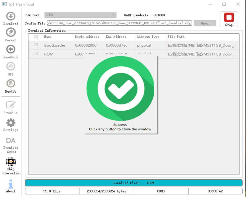
1. Double-click "FlashTool.exe" to start the program
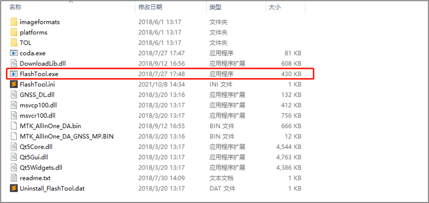
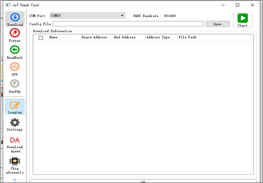
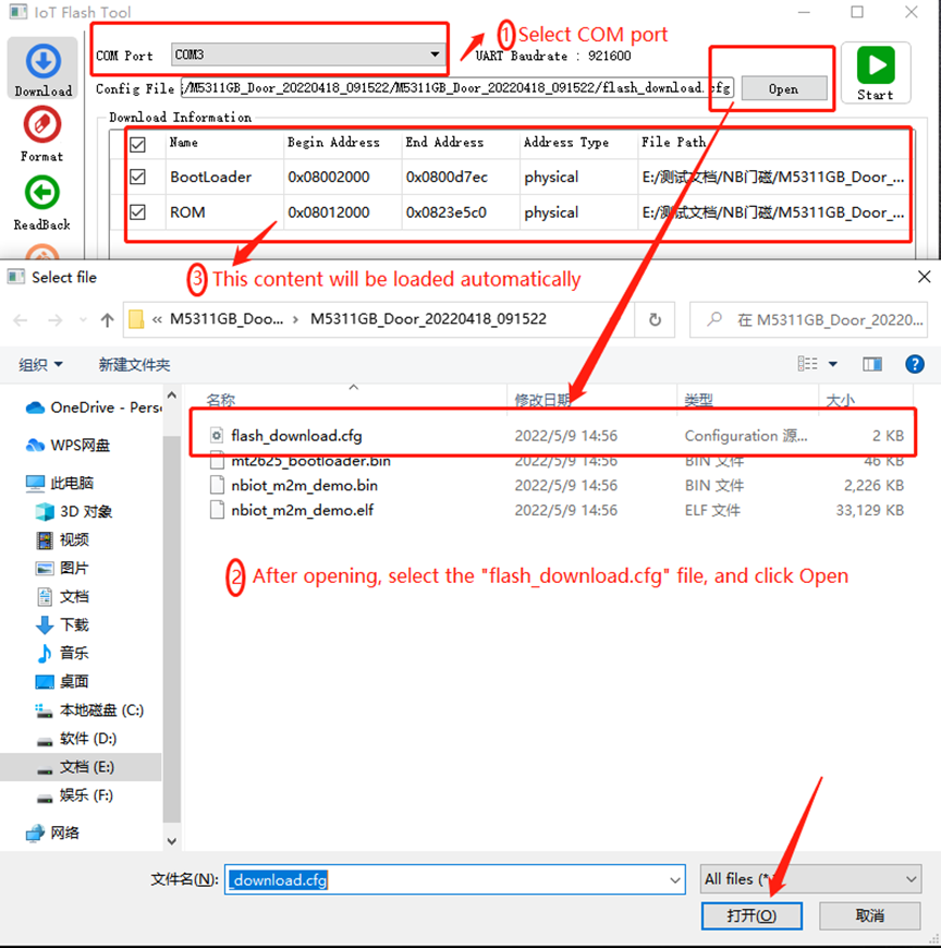
2. Select burn serial port and firmware package to complete the upgrade
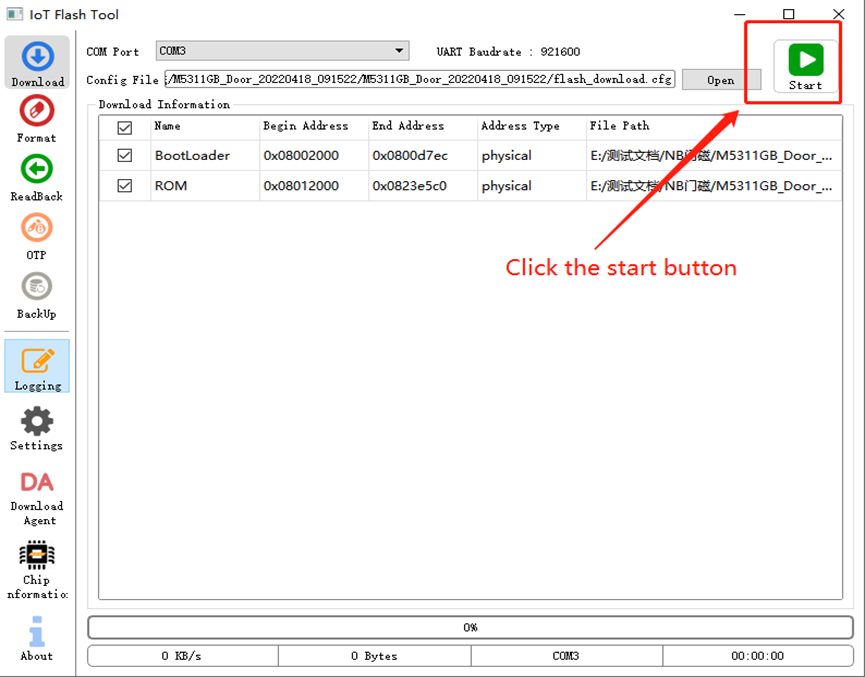
3. Install the battery to the node, and the upgrade will start at this time
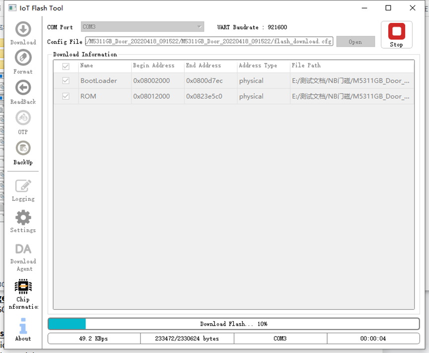
4. The following screenshot appears, indicating that the upgrade has been successful
4. Order Info
Part Number: NDS01
5. Packing Info
Package Includes:
- NDS01 NB-IoT Door Sensor
Dimension and weight:
- Device Size:
- Device Weight:
- Package Size / pcs :
- Weight / pcs :
6. Support
- Support is provided Monday to Friday, from 09:00 to 18:00 GMT+8. Due to different timezones we cannot offer live support. However, your questions will be answered as soon as possible in the before-mentioned schedule.
- Provide as much information as possible regarding your enquiry (product models, accurately describe your problem and steps to replicate it etc) and send a mail to support@dragino.com.