NDDS75 -- NB-IoT Distance Detect Sensor User Manual
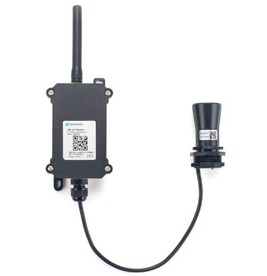
Table of Contents:
- 1. Introduction
- 2. Use NDDS75 to communicate with IoT Server
- 2.1 How it works
- 2.2 Configure the NDDS75
- 2.3 Uplink Payload
- 2.4 Payload Explanation and Sensor Interface
- 2.5 Downlink Payload
- 2.6 Distance alarm function(Since firmware v1.3.2)
- 2.7 Set the number of data to be uploaded and the recording time
- 2.8 Read or Clear cached data
- 2.9 LED Indicator
- 2.10 Firmware Change Log
- 2.11 Battery & Power Consumption
- 3. Access NB-IoT Module
- 4. Using the AT Commands
- 5. FAQ
- 6. Trouble Shooting
- 7. Order Info
- 8. Packing Info
- 9. Support
1. Introduction
1.1 What is NDDS75 Distance Detection Sensor
The Dragino NDDS75 is a NB-IoT Distance Detection Sensor for Internet of Things solution. It is designed to measure the distance between the sensor and a flat object. The distance detection sensor is a module that uses ultrasonic sensing technology for distance measurement, and temperature compensation is performed internally to improve the reliability of data.
The NDDS75 can be applied to scenarios such as horizontal distance measurement, liquid level measurement, parking management system, object proximity and presence detection, intelligent trash can management system, robot obstacle avoidance, automatic control, sewer, bottom water level monitoring, etc. It detects the distance between the measured object and the sensor, and uploads the value via wireless to IoT Server via NB-IoT Network.
NarrowBand-Internet of Things (NB-IoT) is a standards-based low power wide area (LPWA) technology developed to enable a wide range of new IoT devices and services. NB-IoT significantly improves the power consumption of user devices, system capacity and spectrum efficiency, especially in deep coverage.
NDDS75 supports different uplink methods include TCP, MQTT, UDP and CoAP for different application requirement.
NDDS75 is powered by 8500mAh Li-SOCI2 battery, It is designed for long term use up to 5 years. (Actually Battery life depends on the use environment, update period & uplink method)
To use NDDS75, user needs to check if there is NB-IoT coverage in local area and with the bands NDDS75 supports. If the local operate support it, user needs to get a NB-IoT SIM card from local operator and install NDDS75 to get NB-IoT network connection.

1.2 Features
- NB-IoT Bands: B1/B3/B8/B5/B20/B28 @H-FDD
- Ultra low power consumption
- Distance Detection by Ultrasonic technology
- Flat object range 280mm - 7500mm
- Accuracy: ±(1cm+S*0.3%) (S: Distance)
- Cable Length: 25cm
- AT Commands to change parameters
- Uplink on periodically
- Downlink to change configure
- IP66 Waterproof Enclosure
- Micro SIM card slot for NB-IoT SIM
- 8500mAh Battery for long term use
1.3 Specification
Common DC Characteristics:
- Supply Voltage: 2.1v ~ 3.6v
- Operating Temperature: -40 ~ 85°C
NB-IoT Spec:
- B1 @H-FDD: 2100MHz
- B3 @H-FDD: 1800MHz
- B8 @H-FDD: 900MHz
- B5 @H-FDD: 850MHz
- B20 @H-FDD: 800MHz
- B28 @H-FDD: 700MHz
Battery:
- Li/SOCI2 un-chargeable battery
- Capacity: 8500mAh
- Self Discharge: <1% / Year @ 25°C
- Max continuously current: 130mA
- Max boost current: 2A, 1 second
Power Consumption
- STOP Mode: 10uA @ 3.3v
- Max transmit power: 350mA@3.3v
1.4 Applications
- Smart Buildings & Home Automation
- Logistics and Supply Chain Management
- Smart Metering
- Smart Agriculture
- Smart Cities
- Smart Factory
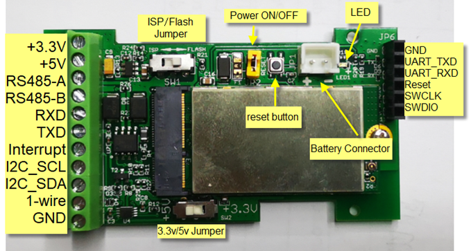
1.5 Pin Definitions
2. Use NDDS75 to communicate with IoT Server
2.1 How it works
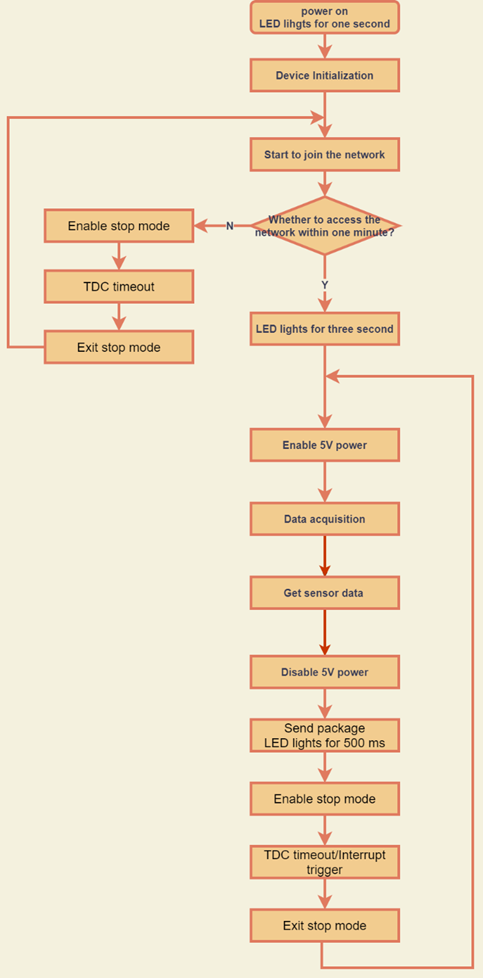
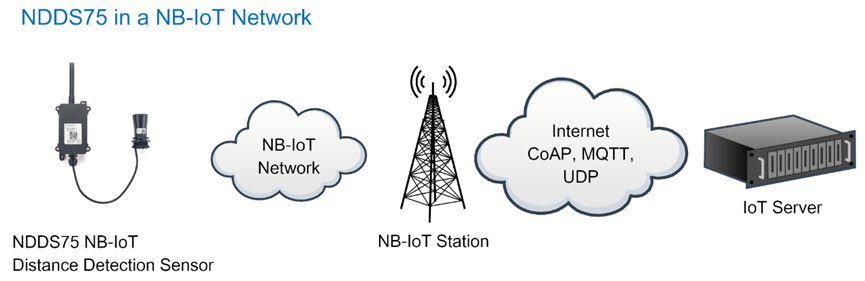
The NDDS75 is equipped with a NB-IoT module, the pre-loaded firmware in NDDS75 will get environment data from sensors and send the value to local NB-IoT network via the NB-IoT module. The NB-IoT network will forward this value to IoT server via the protocol defined by NDDS75.
The diagram below shows the working flow in default firmware of NDDS75:
2.2 Configure the NDDS75
2.2.1 Test Requirement
To use NDDS75 in your city, make sure meet below requirements:
- Your local operator has already distributed a NB-IoT Network there.
- The local NB-IoT network used the band that NDDS75 supports.
- Your operator is able to distribute the data received in their NB-IoT network to your IoT server.
Below figure shows our testing structure. Here we have NB-IoT network coverage by China Mobile, the band they use is B8. The NDDS75 will use CoAP(120.24.4.116:5683) or raw UDP(120.24.4.116:5601) or MQTT(120.24.4.116:1883)or TCP(120.24.4.116:5600)protocol to send data to the test server.
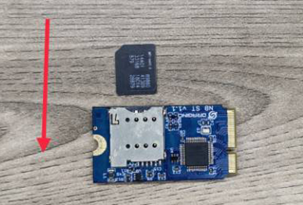
2.2.2 Insert SIM card
Insert the NB-IoT Card get from your provider.
User need to take out the NB-IoT module and insert the SIM card like below:
2.2.3 Connect USB – TTL to NDDS75 to configure it
User need to configure NDDS75 via serial port to set the Server Address / Uplink Topic to define where and how-to uplink packets. NDDS75 support AT Commands, user can use a USB to TTL adapter to connect to NDDS75 and use AT Commands to configure it, as below.
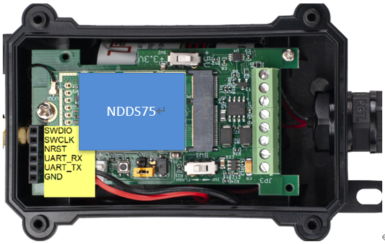
Connection:
USB TTL GND <----> GND
USB TTL TXD <----> UART_RXD
USB TTL RXD <----> UART_TXD
In the PC, use below serial tool settings:
- Baud: 9600
- Data bits: 8
- Stop bits: 1
- Parity: None
- Flow Control: None
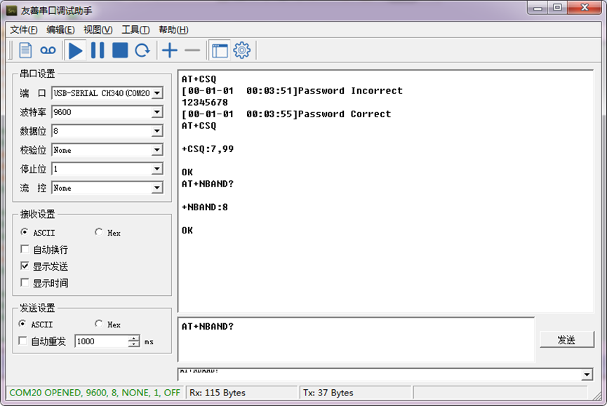
Make sure the switch is in FLASH position, then power on device by connecting the jumper on NDDS75. NDDS75 will output system info once power on as below, we can enter the password: 12345678 to access AT Command input.

Note: the valid AT Commands can be found at: https://www.dropbox.com/sh/aaq2xcl0bzfu0yd/AAAEAHRa7Io_465ds4Y7-F3aa?dl=0
2.2.4 Use CoAP protocol to uplink data
Note: if you don't have CoAP server, you can refer this link to set up one: http://wiki.dragino.com/xwiki/bin/view/Main/Set%20up%20CoAP%20Server/
Use below commands:
AT+PRO=1 // Set to use CoAP protocol to uplink
AT+SERVADDR=120.24.4.116,5683 // to set CoAP server address and port
AT+URI=5,11,"mqtt",11,"coap",12,"0",15,"c=text1",23,"0" // Set COAP resource path
For parameter description, please refer to AT command set
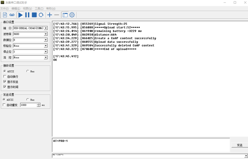
After configure the server address and reset the device (via AT+ATZ ), NDDS75 will start to uplink sensor values to CoAP server.

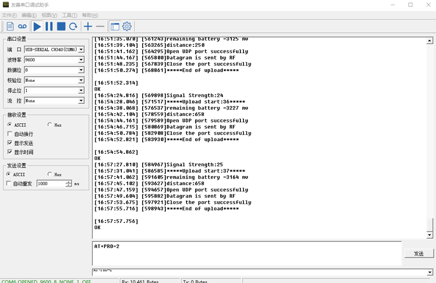
2.2.5 Use UDP protocol to uplink data(Default protocol)
- AT+PRO=2 // Set to use UDP protocol to uplink
- AT+SERVADDR=120.24.4.116,5601 // to set UDP server address and port
2.2.6 Use MQTT protocol to uplink data
- AT+PRO=3 // Set to use MQTT protocol to uplink
- AT+SERVADDR=120.24.4.116,1883 // Set MQTT server address and port
- AT+CLIENT=CLIENT // Set up the CLIENT of MQTT
- AT+UNAME=UNAME // Set the username of MQTT
- AT+PWD=PWD // Set the password of MQTT
- AT+PUBTOPIC=NDDS75_PUB // Set the sending topic of MQTT
- AT+SUBTOPIC=NDDS75_SUB // Set the subscription topic of MQTT
MQTT protocol has a much higher power consumption compare vs UDP / CoAP protocol. Please check the power analyze document and adjust the uplink period to a suitable interval.
2.2.7 Use TCP protocol to uplink data
- AT+PRO=4 // Set to use TCP protocol to uplink
- AT+SERVADDR=120.24.4.116,5600 // to set TCP server address and port
2.2.8 Change Update Interval
User can use below command to change the uplink interval.
- AT+TDC=600 // Set Update Interval to 600s
NOTE:
1. By default, the device will send an uplink message every 1 hour.
2. When the firmware version is v1.3.2 and later firmware:
By default, the device will send an uplink message every 2 hours. Each Uplink Include 8 set of records in this 2 hour (15 minute interval / record).
2.3 Uplink Payload
2.3.1 Before Firmware v1.3.2
In this mode, uplink payload includes in total 14 bytes
Size(bytes) | 6 | 2 | 2 | 1 | 2 | 1 |
|---|---|---|---|---|---|---|
| Value | Device ID | Ver | BAT | Signal Strength | Distance (unit: mm) | Interrupt |
If we use the MQTT client to subscribe to this MQTT topic, we can see the following information when the NDDS75 uplink data.
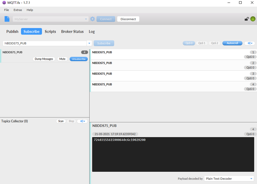
The payload is ASCII string, representative same HEX:
0x 724031556159 0064 0c6c 19 0292 00
where :
- Device ID: 0x724031556159 = 724031556159
- Version: 0x0064=100=1.0.0
- BAT: 0x0c6c = 3180 mV = 3.180V
- Signal: 0x19 = 25
- Distance: 0x0292= 658 mm
- Interrupt: 0x00 = 0
2.3.2 Since firmware v1.3.2
In this mode, uplink payload includes 69 bytes in total by default.
Each time the device uploads a data package, 8 sets of recorded data will be attached. Up to 32 sets of recorded data can be uploaded.
| Size(bytes) | 8 | 2 | 2 | 1 | 1 | 1 | 2 | 4 | 2 | 4 |
| Value | Device ID | Ver | BAT | Signal Strength | MOD | Interrupt | Distance | Timestamp | Distance | Timestamp....... |
If we use the MQTT client to subscribe to this MQTT topic, we can see the following information when the NDDS75 uplink data.
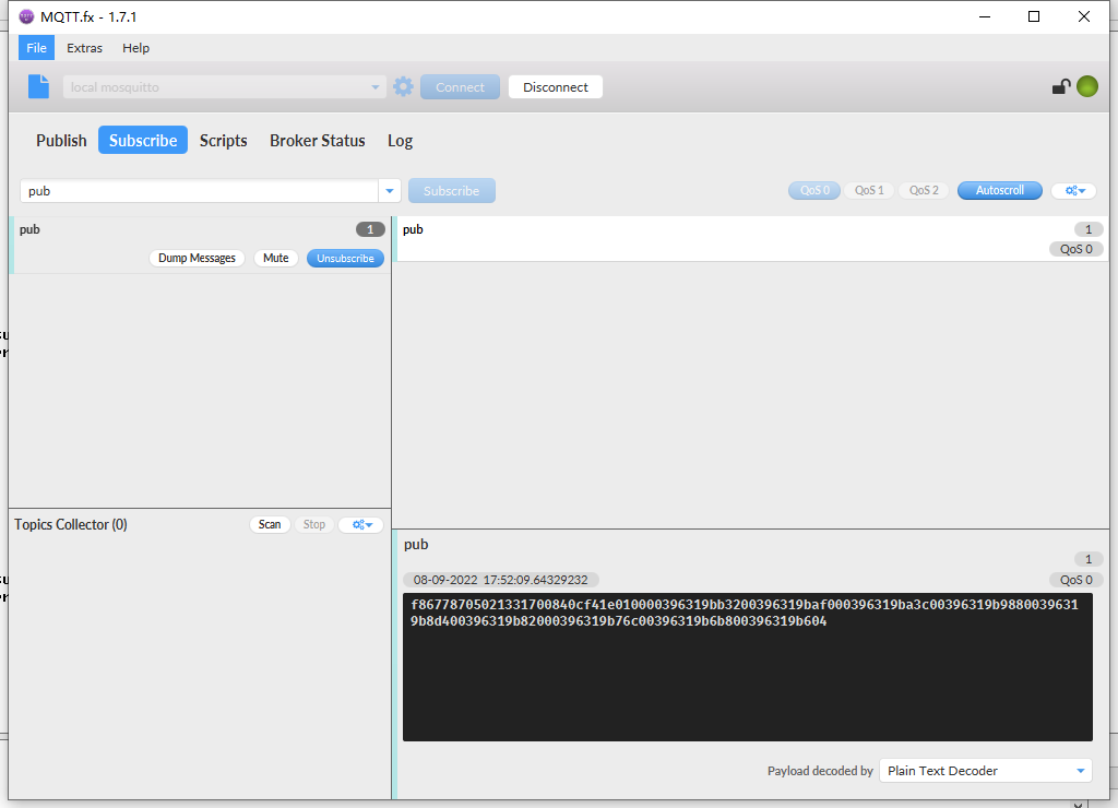
The payload is ASCII string, representative same HEX:
0x f867787050213317 0084 0cf4 1e 01 00 0039 6315537b 00396319baf0 00396319ba3c 00396319b988 00396319b8d4 00396319b820 00396319b76c 00396319b6b8 00396319b604
where:
- Device ID: f867787050213317 = f867787050213317
- Version: 0x0084=132=1.3.2
- BAT: 0x0cf4 = 3316 mV = 3.316V
- Singal: 0x1e = 30
- Mod: 0x01 = 1
- Interrupt: 0x00= 0
- Distance: 0x0039= 57 = 57
- Time stamp: 0x6315537b =1662342011 (Unix Epoch Time)
- Distance,Time stamp: 00396319baf0
- 8 sets of recorded data: Distance,Time stamp : 00396319ba3c,.......
2.4 Payload Explanation and Sensor Interface
2.4.1 Device ID
By default, the Device ID equal to the last 6 bytes of IMEI.
User can use AT+DEUI to set Device ID
Example :
AT+DEUI=A84041F15612
The Device ID is stored in a none-erase area, Upgrade the firmware or run AT+FDR won't erase Device ID.
NOTE: When the firmware version is v1.3.2 and later firmware:
By default, the Device ID equal to the last 15 bits of IMEI.
User can use AT+DEUI to set Device ID
Example :
AT+DEUI=868411056754138
2.4.2 Version Info
Specify the software version: 0x64=100, means firmware version 1.00.
For example: 0x00 64 : this device is NDDS75 with firmware version 1.0.0.
2.4.3 Battery Info
Ex1: 0x0B45 = 2885mV
Ex2: 0x0B49 = 2889mV
2.4.4 Signal Strength
NB-IoT Network signal Strength.
Ex1: 0x1d = 29
0 -113dBm or less
1 -111dBm
2...30 -109dBm... -53dBm
31 -51dBm or greater
99 Not known or not detectable
2.4.5 Distance
Get the distance. Flat object range 280mm - 7500mm.
For example, if the data you get from the register is 0x0B 0x05, the distance between the sensor and the measured object is 0B05(H) = 2821(D) = 2821mm.
2.4.6 Digital Interrupt
Digital Interrupt refers to pin GPIO_EXTI, and there are different trigger methods. When there is a trigger, the NDDS75 will send a packet to the server.
The command is:
AT+INTMOD=3 // (more info about INMOD please refer AT Command Manual).
The lower four bits of this data field shows if this packet is generated by interrupt or not. Click here for the hardware and software set up.
Example:
0x(00): Normal uplink packet.
0x(01): Interrupt Uplink Packet.
2.4.7 +5V Output
NDDS75 will enable +5V output before all sampling and disable the +5v after all sampling.
The 5V output time can be controlled by AT Command.
AT+5VT=1000
Means set 5V valid time to have 1000ms. So the real 5V output will actually have 1000ms + sampling time for other sensors.
2.5 Downlink Payload
By default, NDDS75 prints the downlink payload to console port.
| Downlink Control Type | FPort | Type Code | Downlink payload size(bytes) |
| TDC (Transmit Time Interval) | Any | 01 | 4 |
| RESET | Any | 04 | 2 |
| INTMOD | Any | 06 | 4 |
Examples:
Set TDC
If the payload=0100003C, it means set the END Node's TDC to 0x00003C=60(S), while type code is 01.
Payload: 01 00 00 1E TDC=30S
Payload: 01 00 00 3C TDC=60S
Reset
If payload = 0x04FF, it will reset the NDDS75
- INTMOD
Downlink Payload: 06000003, Set AT+INTMOD=3
2.6 Distance alarm function(Since firmware v1.3.2)
➢ AT Command:
AT+ LDDSALARM=min,max
² When min=0, and max≠0, Alarm higher than max
² When min≠0, and max=0, Alarm lower than min
² When min≠0 and max≠0, Alarm higher than max or lower than min
Example:
AT+ LDDSALARM=260,2000 // Alarm when distance lower than 260.
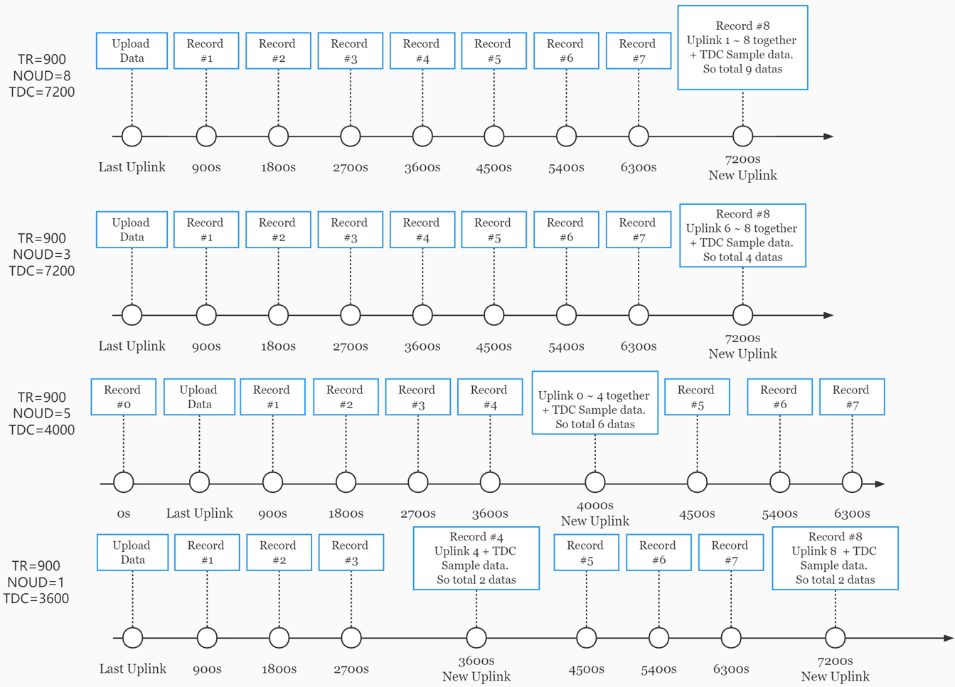
2.7 Set the number of data to be uploaded and the recording time
➢ AT Command:
- AT+TR=900 // The unit is seconds, and the default is to record data once every 900 seconds.( The minimum can be set to 180 seconds)
- AT+NOUD=8 // The device uploads 8 sets of recorded data by default. Up to 32 sets of record data can be uploaded.
The diagram below explains the relationship between TR, NOUD, and TDC more clearly:
2.8 Read or Clear cached data
➢ AT Command:
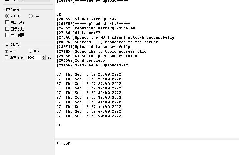
- AT+CDP // Read cached data
- AT+CDP=0 // Clear cached data
2.9 LED Indicator
The NDDS75 has an internal LED which is to show the status of different state.
- When power on, NDDS75 will detect if sensor probe is connected, if probe detected, LED will blink four times. (no blinks in this step is no probe)
- Then the LED will be on for 1 second means device is boot normally.
- After NDDS75 join NB-IoT network. The LED will be ON for 3 seconds.
- For each uplink probe, LED will be on for 500ms.
2.10 Firmware Change Log
Download URL & Firmware Change log: https://www.dropbox.com/sh/3hb94r49iszmstx/AADvSJcXxahEUfxqKWVnZx-La?dl=0
Upgrade Instruction: Upgrade Firmware
2.11 Battery & Power Consumption
NDDS75 uses ER26500 + SPC1520 battery pack. See below link for detail information about the battery info and how to replace.
Battery Info & Power Consumption Analyze .
3. Access NB-IoT Module
Users can directly access the AT command set of the NB-IoT module.
The AT Command set can refer the BC35-G NB-IoT Module AT Command: https://www.dragino.com/downloads/index.php?dir=datasheet/other_vendors/BC35-G/
4. Using the AT Commands
4.1 Access AT Commands
See this link for detail: https://www.dropbox.com/sh/aaq2xcl0bzfu0yd/AAAEAHRa7Io_465ds4Y7-F3aa?dl=0
AT+<CMD>? : Help on <CMD>
AT+<CMD> : Run <CMD>
AT+<CMD>=<value> : Set the value
AT+<CMD>=? : Get the value
General Commands
AT : Attention
AT? : Short Help
ATZ : MCU Reset
AT+TDC : Application Data Transmission Interval
AT+CFG : Print all configurations
AT+CFGMOD : Working mode selection
AT+INTMOD : Set the trigger interrupt mode
AT+5VT : Set extend the time of 5V power
AT+PRO : Choose agreement
AT+WEIGRE : Get weight or set weight to 0
AT+WEIGAP : Get or Set the GapValue of weight
AT+RXDL : Extend the sending and receiving time
AT+CNTFAC : Get or set counting parameters
AT+SERVADDR : Server Address
AT+TR : Get or Set record time"
AT+APN : Get or set the APN
AT+FBAND : Get or Set whether to automatically modify the frequency band
AT+DNSCFG : Get or Set DNS Server
AT+GETSENSORVALUE : Returns the current sensor measurement
AT+NOUD : Get or Set the number of data to be uploaded
AT+CDP : Read or Clear cached data
AT+LDDSALARM : Get or Set alarm of distance
COAP Management
AT+URI : Resource parameters
MQTT Management
AT+CLIENT : Get or Set MQTT client
AT+UNAME : Get or Set MQTT Username
AT+PWD : Get or Set MQTT password
AT+PUBTOPIC : Get or Set MQTT publish topic
AT+SUBTOPIC : Get or Set MQTT subscription topic
Information
AT+FDR : Factory Data Reset
AT+PWORD : Serial Access Password
5. FAQ
5.1 How to Upgrade Firmware
User can upgrade the firmware for 1) bug fix, 2) new feature release.
Please see this link for how to upgrade: http://wiki.dragino.com/xwiki/bin/view/Main/Firmware%20Upgrade%20Instruction%20for%20STM32%20base%20products/#H2.HardwareUpgradeMethodSupportList
Notice, NDDS75 and LDDS75 share the same mother board. They use the same connection and method to update.
6. Trouble Shooting
6.1 Connection problem when uploading firmware
6.2 AT Command input doesn't work
In the case if user can see the console output but can't type input to the device. Please check if you already include the ENTER while sending out the command. Some serial tool doesn't send ENTER while press the send key, user need to add ENTER in their string.
6.3 Not able to connect to NB-IoT network and keep showing "Signal Strength:99".
This means sensor is trying to join the NB-IoT network but fail. Please see this link for trouble shooting for signal strenght:99.
7. Order Info
Part Number: NSDDS75
8. Packing Info
Package Includes:
- NDDS75 NB-IoT Distance Detect Sensor Node x 1
- External antenna x 1
Dimension and weight:
- Device Size: 13.0 x 5 x 4.5 cm
- Device Weight: 150g
- Package Size / pcs : 15 x 12x 5.5 cm
- Weight / pcs : 220g
9. Support
- Support is provided Monday to Friday, from 09:00 to 18:00 GMT+8. Due to different timezones we cannot offer live support. However, your questions will be answered as soon as possible in the before-mentioned schedule.
- Provide as much information as possible regarding your enquiry (product models, accurately describe your problem and steps to replicate it etc) and send a mail to support@dragino.com