LTC2 - LoRaWAN Temperature Transmitter User Manual
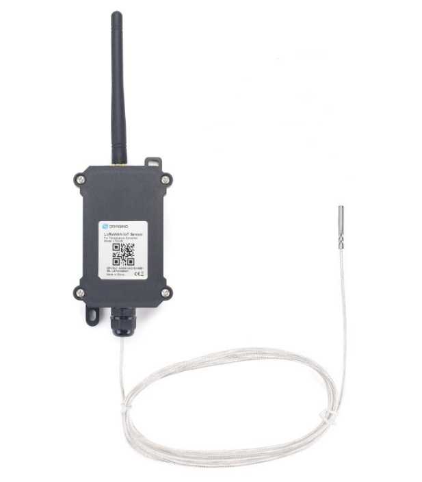
Table of Contents:
- 1. Introduction
- 2. How to use LTC2?
- 3. Configure LTC2 via AT Command or LoRaWAN Downlink
- 3.1 Set Transmit Interval Time
- 3.2 Enable PT100 channels
- 3.3 Set External Sensor Mode
- 3.4 Quit AT Command
- 3.5 Set system time
- 3.6 Set Time Sync Mode
- 3.7 Set Time Sync Interval
- 3.8 Retrieve data
- 3.9 Enable Alarm mode
- 3.10 Alarm check time
- 3.11 Set Alarm Threshold
- 3.12 Set Calibrate Value
- 3.13 Poll Calibrate Value
- 3.14 Print data entries base on page
- 3.15 Print last few data entries
- 3.16 Clear Flash Record
- 4. Battery & Power Consumption
- 5. Firmware Change Log and Upload Firmware
- 6. FAQ
- 7. Trouble Shooting
- 8. Order Info
- 9. Packing Info
- 10. Support
1. Introduction
1.1 What is LTC2 LoRaWAN Temperature Transmitter
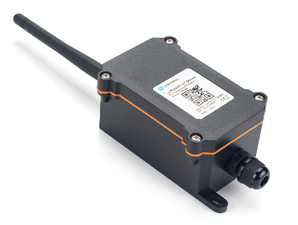
The Dragino LTC2 Industrial LoRaWAN Temperature Transmitter is designed to monitor temperature for different environment. It supports to read PT100 probe and convert the value to temperature and uplink to IoT server via LoRaWAN protocol.
LTC2 supports Datalog feature. User can retrieve the sensor value via LoRaWAN downlink command.
LTC2 is powered by 8500mA Li-SOCI2 battery for long time measurement. The battery can run 2~10 years depends on the network environment and working mode.
Each LTC2 has two internal 24-bit ADC interfaces and are calibrated on 12 set resistors to make sure the accuracy measurement on wide range.
LTC2 is LoRaWAN v1.0.3 compatible. Each LTC2 is pre-load with a set of unique keys for LoRaWAN registration, register these keys to local LoRaWAN server and it will auto connect after power on.
1.2 Features
- LoRaWAN v1.0.3 Class A
- max: 2 x monitor temperature channels
- Support 3 -wire PT-100
- 8500mAh Li-SOCI2 Battery
- Firmware upgrade via console
- Wall Mountable
- Configurable via LoRa or UART
- Datalog and retrieve via LoRaWAN
- Use pre-load PT100 probe or 3rd PT100 probe
- Factory calibration for different resistance range
- Support accuracy measure of resistance and upload
- Battery Monitoring and upload
- Operation Temperature: -40 ~ 65 ℃
1.3 Applications
- Logistics and Supply Chain Management
- Food management
- Cold chains solution
- Industrial Monitoring and Control
1.4 Hardware Change log
LTC2 v1.0: Release.
1.5 Pin Definitions and Switch
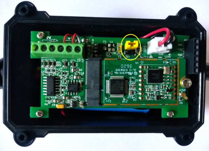
1.5.1 Jumper JP2 ( Power ON)
Put a jumper on JP2 will power on the LTC2.
1.5.2 LED
The LED will flash in below case.
1. Send an uplink packet
1.5.3 PT100 Interfaces
There are two independent channels to connect 2 x PT100 probes.
Each channel has 3-wire connection for 3-wire PT100 probes.
1.5.4 Reset Button
Press this button will reboot the LTC2
1.6 Probe Variant
LTC2 provide default probe version. See below for the variant:
Model | Photo | Description |
|---|---|---|
LTC2-SI |
| Standard IP68 Probe Version
|
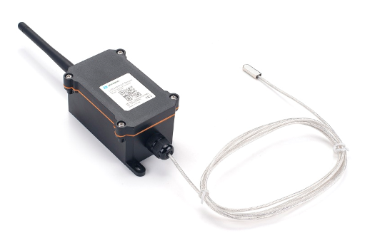
LTC2-LT |
| Low Temperature Version
|
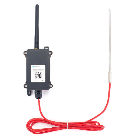
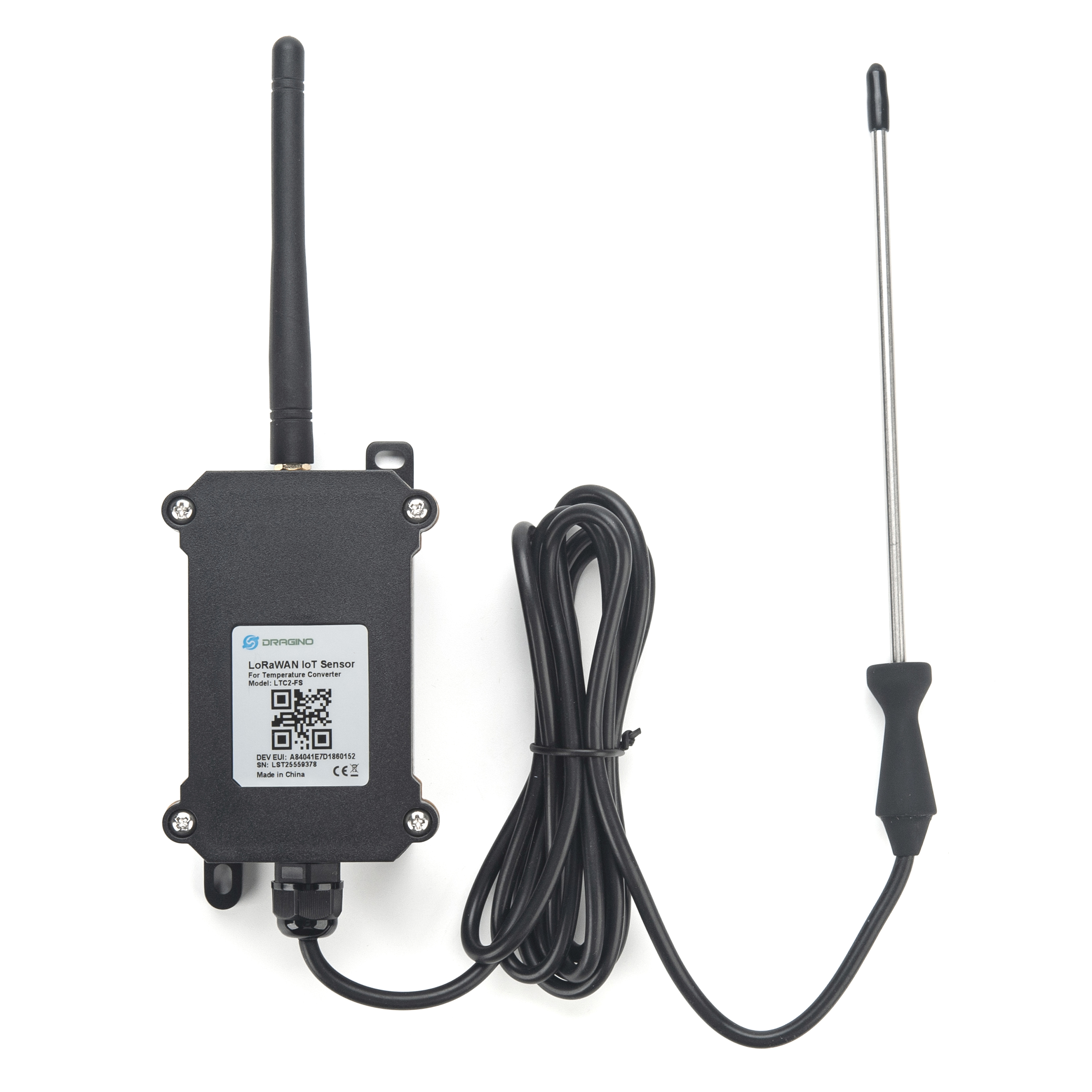
LTC2-FS |
| Food Safety Version
|
| LTC-FSA |
| Food Safety Version
|
LTC2-FT |
| Flat Type Version
|
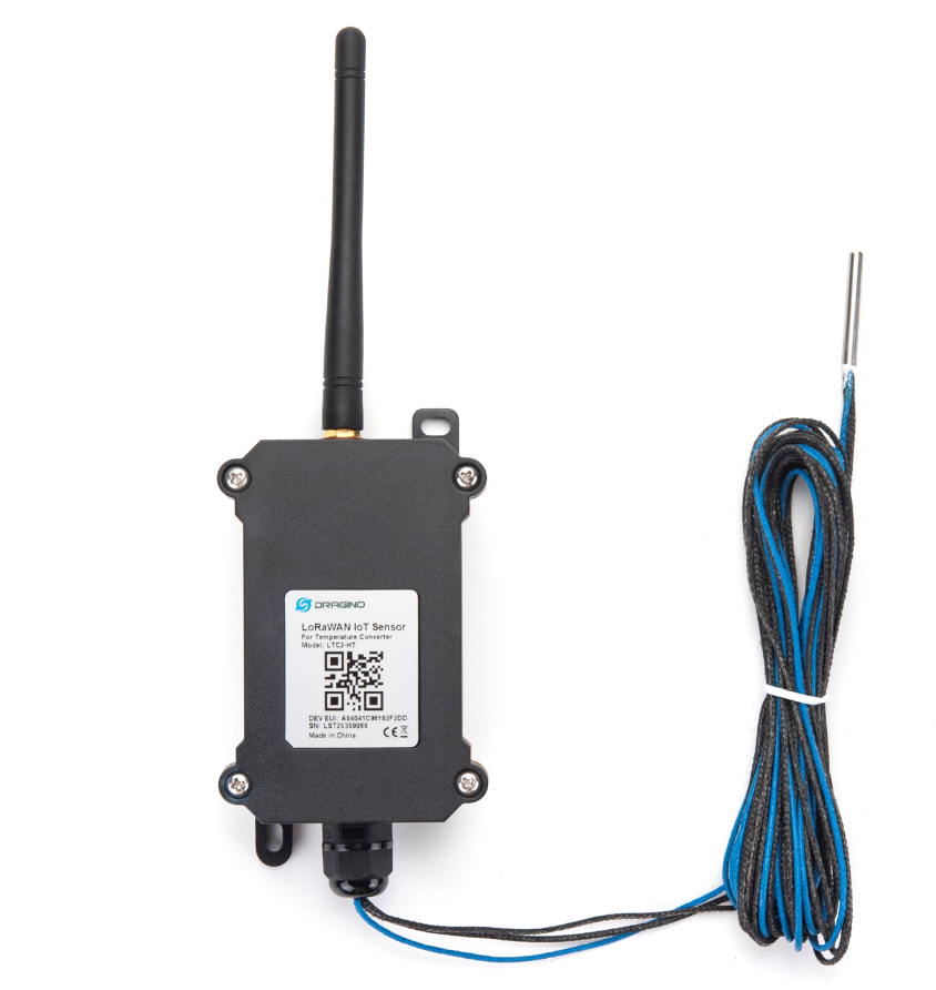
| LTC2-HT |
| High Temperature Version
Suitable Environment: High Temperature |
| LTC2-NA |
| No Probe version:
Connect to customized probe |
2. How to use LTC2?
2.1 Connect to PT100 sensors
LTC2 has different probe option provided for ordering, if user has LTC2 with probe, just skip this step. If user want to connect to a 3rd party PT100 probe, please see CONNECT A 3rd PARTY PT100 probe.
2.2 How it works?
The LTC2 is working in LoRaWAN OTAA Class A mode. Each LTC2 is shipped with a worldwide unique set of OTAA and ABP keys. User needs to input the OTAA or ABP keys in the LoRaWAN network server so to register. LTC2 will join the LoRaWAN network and start to transmit data. The default period for each uplink is 20 minutes.
On each uplink, LTC2 will check its two ADC Interfaces and get the temperature from the sensor and send out to server.
2.3 Quick guide to connect to LoRaWAN server (OTAA)
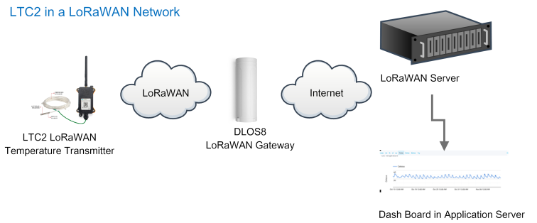
Here is an example for how to join the TTN v3 LoRaWAN Server. Below is the network structure, in this demo we use DLOS8 as LoRaWAN gateway.
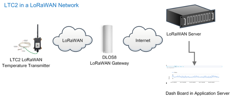

The DLOS8 is already set to connect to TTN . Rest we need to is register the LTC2 to TTN v3:
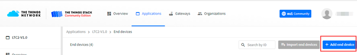
2.3.1 Step 1: Create a device in TTN with the OTAA keys from LTC2
Below is TTN screen shot:
- Create Application first.
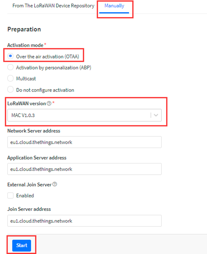
- Manually Add a LoRaWAN End Device device. Choose OTAA and MAC v1.0.3
Input the OTAA keys for LTC2.
Each LTC2 is shipped with a sticker with the default device EUI as below:
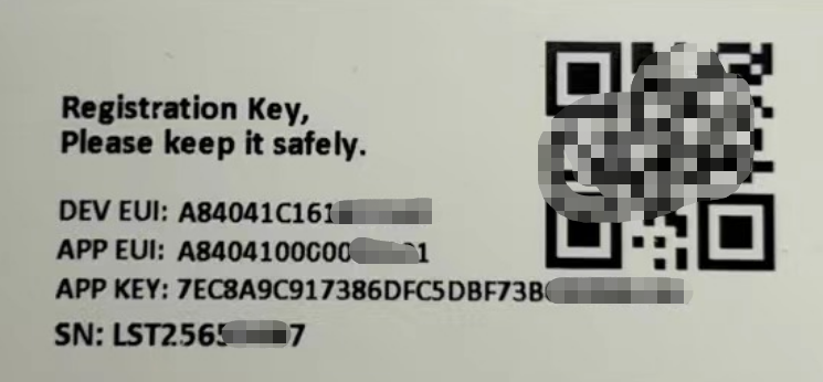
- Input these keys to device portal.
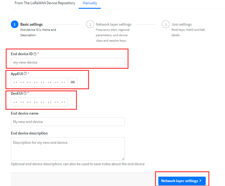
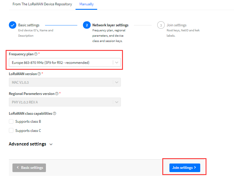
- Choose the Frequency band for this end node.
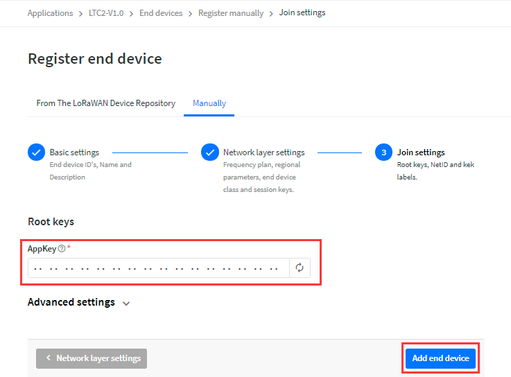
- Input APP Key in this page as well.
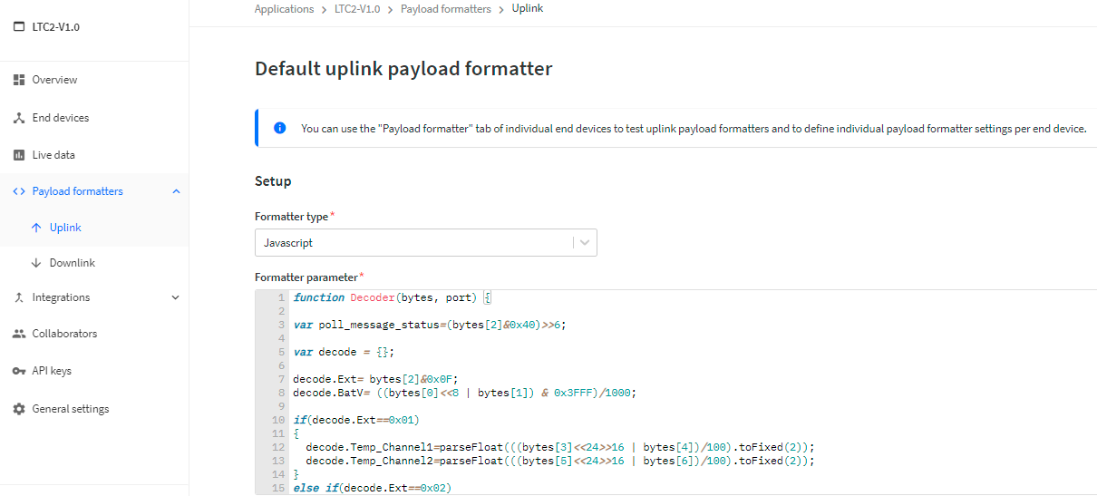
Add payload formatter So TTNv3 knows how to parse the LTC2 upload value.
The payload for TTN can be found at below link: ttps://github.com/dragino/dragino-end-node-decoder
2.3.2 Step 2: Power on LTC2
LTC2 is power off when ship from factory.
Put a Jumper on JP2 to power on the device.
After power on, LTC2 will auto join to TTN network via the LoRaWAN coverage by DLOS8. After join success, LTC2 will start to update message to IoT server.
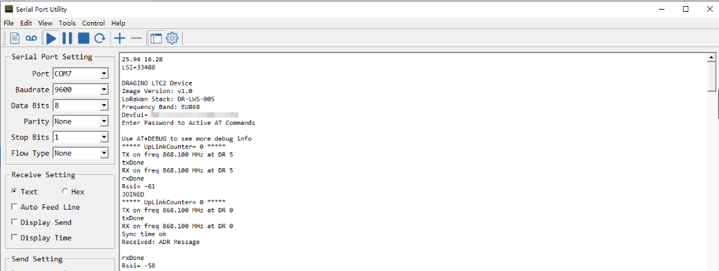
Below is an example uplink message which shows the LTC2 is sending Join Request to TTNv3.
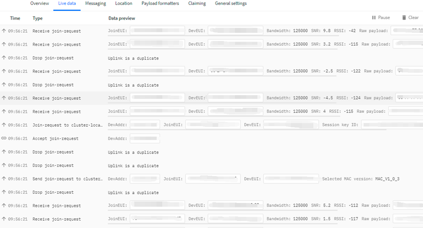
After join successful, LTC2 will send uplink message with the sensor value.
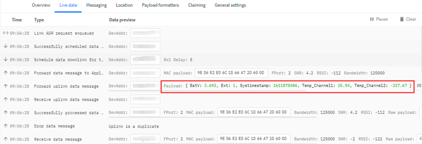
Above value shows Channel1 detect 25.94 degree. There is no PT100 connected on Channel 2, so it shows -327.67.
2.4 Uplink Payload
Below is the uplink payload which shows.
Size(bytes) | 2 | 1 | 2 | 2 | 4 |
|---|---|---|---|---|---|
| Value |
BAT
Ex1: 0x0E3C ⇒ 3644 (mV) = 3.644 V
Status & EXT
| Bits | 7 | 6 | 5 | 4 | [3:0] |
| Status&Ext | Not Defined | Poll Message FLAG | Sync time OK | Unix Time Request | Ext: 0b(1001) |
- Poll Message Flag: 1: This message is a poll message reply, 0: means this is a normal uplink.
- Sync time OK: 1: Set time ok, 0: N/A. After time SYNC request is send, device will set this bit to 0 until got the time stamp from application server.
- Unix Time Request: 1: Request server downlink Unix time, 0 : N/A. In this mode, LTC2 will set this bit to 1 every 10 day to request a time SYNC. (AT+SYNCMOD to set this)
- EXT: The decode method for Channel 1 data and Channel 2 data
- 0b(0001): Upload PT100 temperature, with 2 decimals, range: -327.67 ~ 327.67 ℃
- 0b(0010): Upload PT100 temperature, with 1 decimals, range: -3276.7 ~ 3276.7 ℃
- 0b(0011): Upload Resistance instead of Temperature, range: -327.67~ 327.67 ohm
Channel 1 data and Channel 2 data
| Example Payload on channel 1 or channel 2 | Sensor Value when EXT=0b(0001) | Sensor Value when EXT=0b(0010) | Sensor Value when EXT=0b(0011) |
| 0x1422 | 0x1422/100=51.54℃ | 0x1422/100=515.4℃ | 0x1422/100=51.54Ω |
| OXEC2D | (0XEC2D-65536)/100=-50.75℃ | (0XEC2D-65536)/10=-507.5℃ | 0XEC2D/100=604.61Ω |
Unix TimeStamp
Refer to Datalog feature.
Example Uplink Payload:
Uplink payload example 1: 0CE9011422EC2D6073E83B
- Bat voltage:0x0CE9 =3305mV
- Ext=0x01
- Channel1 temp=0x1422/100=51.54 ℃
- Channel2 temp=(0xEC2D-65536)/100=-50.75 ℃
- System timestamp=0x6073E83B= 1618208827(UTC)
If payload is: EC2DH : (EC2D & 8000 == 1), temp = (EC2DH - 65536)/100 = -50.75 ℃
(EC2D & 8000: Judge whether the highest bit is 1, when the highest bit is 1, it is negative)
Uplink payload example 2: 0CED020203FE056073E697
- Bat voltage:0x0CED =3309mV
- Ext=0x02
- Channel1 temp=0x0203/10=515.4 ℃
- Channel2 temp=(0xFE05-65536)/10=-507.5 ℃
- System timestamp=0x6073E697=1618208407(UTC)
If payload is: FE05H : (FE05 & 8000 == 1) , temp = (FE05H - 65536)/100 = 507.5 ℃
(EC2D & 8000: Judge whether the highest bit is 1, when the highest bit is 1, it is negative)
Uplink payload example 3 : 0CE9032EDE1F406073E967
- Bat voltage:0x0CE9 =3305mV
- Ext=0x03
- Channel1 res=0x2EDE/100=119.98 ohm
- Channel2 res=0x1F40/100=80.00 ohm
- System timestamp=0x6073E967= 1618209127(UTC)
2.5 Datalog Feature
LTC2 will auto get the time from LoRaWAN server during Join, and each uplink will then include a timestamp. When user want to retrieve sensor value, user can send a poll command from the IoT platform to ask sensor to send value in the required time slot.
2.5.1 Unix TimeStamp
LTC2 uses Unix TimeStamp format based on
Users can get this time from the link: https://www.epochconverter.com/ :
Below is the converter example
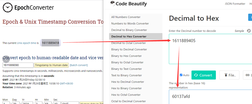
So, we can use AT+TIMESTAMP=1611889405 or downlink 3060137afd00 to set current time 2021 – Jan -- 29 Friday 03:03:25
2.5.2 Set Device Time
There are two ways to set the device's time:
1. Through LoRaWAN MAC Command (Default settings)
Users need to set SYNCMOD=1 to enable sync time via the MAC command.
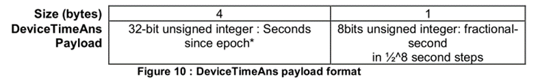
Once LTC2 Joined LoRaWAN network, it will send the MAC command (DeviceTimeReq) and server will reply with (DeviceTimeAns) to send the current time to LTC2. If LTC2 fails to get the time from server, LTC2 will use the internal time and wait for next time request (AT+SYNCTDC to set time request period, default is 10 days).
Note: LoRaWAN Server needs to support LoRaWAN v1.0.3(MAC v1.0.3) or higher to support this MAC command feature, Chirpstack,TTN v3 and loriot support but TTN v2 doesn't support. If server doesn't support this command, it will through away uplink packet with this command, so user will lose the packet with time request for TTN v2 if SYNCMOD=1.
2. Manually Set Time
Users need to set SYNCMOD=0 to manual time, otherwise, the user set time will be overwritten by the time set by the server.
2.5.3 Poll sensor value
Users can poll sensor values based on timestamps. Below is the downlink command.
| Downlink Command to poll Open/Close status (0x31) | |||
|---|---|---|---|
| 1byte | 4bytes | 4bytes | 1byte |
| 31 | Timestamp start | Timestamp end | Uplink Interval |
Timestamp start and Timestamp end use Unix TimeStamp format as mentioned above. Devices will reply with all data log during this time period, use the uplink interval.
For example, downlink command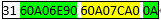
Is to check 2021/5/16 01:00:00 to 2021/5/16 02:00:00's data
Uplink Internal =10s,means LTC2 will send one packet every 10s. range 5~255s.
2.5.4 Datalog Uplink payload
When server senser a datalog polling to LTC2, LTC2 will reply with one or more uplink messages as reply. Each uplink message includes multiply data entries value. Each entry has the same payload format as normal uplink payload.
Note:
- Poll Message Flag is set to 1.
- Each data entry is 11 bytes, to save airtime and battery, devices will send max bytes according to the current DR and Frequency bands.
For example, in US915 band, the max payload for different DR is:
- DR0: max is 11 bytes so one entry of data
- DR1: max is 53 bytes so devices will upload 4 entries of data (total 44 bytes)
- DR2: total payload includes 11 entries of data
- DR3: total payload includes 22 entries of data.
If devise doesn't have any data in the polling time. Device will uplink 11 bytes of 0
Example:
If LTC2 has below data inside Flash:
| Flash Add | Unix Time | Ext | BAT voltage | Value |
| 8021630 | systime= 2021/5/16 01:17:44 | 1 | 3684 | Temp1=28.89 Temp2=-327.67 |
| 8021640 | systime= 2021/5/16 01:37:44 | 1 | 3681 | Temp1=28.79 Temp2=-327.67 |
| 8021650 | systime= 2021/5/16 01:57:44 | 1 | 3681 | Temp1=28.67 Temp2=-327.67 |
| 8021660 | systime= 2021/5/16 02:17:44 | 1 | 3684 | Temp1=28.60 Temp2=-327.67 |
| 8021670 | systime= 2021/5/16 02:37:44 | 1 | 3684 | Temp1=28.56 Temp2=-327.67 |
| 8021680 | systime= 2021/5/16 02:57:44 | 1 | 3684 | Temp1=28.52 Temp2=-327.67 |
| 8021690 | systime= 2021/5/16 03:17:44 | 1 | 3684 | Temp1=28.51 Temp2=-327.67 |
| 80216A0 | systime= 2021/5/16 03:37:44 | 1 | 3684 | Temp1=28.50 Temp2=-327.67 |
| 80216B0 | systime= 2021/5/16 03:57:44 | 1 | 3684 | Temp1=28.46 Temp2=-327.67 |
If user send below downlink command: 3160A06E9060A098C00A
Where : Start time: 60A06E90 = time 21/5/16 01:00:00
Stop time: 60A098C0 = time 21/5/16 04:00:00
LTC2 will uplink this payload.
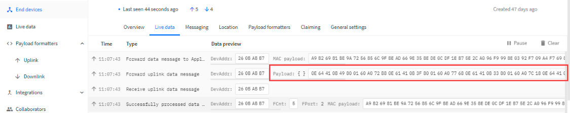
0E64410B49800160A072B80E61410B3F800160A077680E61410B33800160A07C180E64410B2C800160A080C80E64410B28800160A085780E64410B24800160A08A280E64410B23800160A08ED80E64410B22800160A093880E64410B1E800160A09838
Where the first 11 bytes is for the first entry:
0E64410B49800160A072B8
Bat voltage: 0x0E64 =3684mV
poll message flag & Ext=0x41,means reply data,Ext=1
Channel1 temp=0x0B49/100=28.89℃
Channel2 temp=0x8001/100=-327.67℃
System timestamp=0x60A072B8= 1621127864(UTC)
2.6 Alarm Mode
LTC2 can monito the temperature in every CTTEMP time, when the temperature exceed the limit , it will uplink the sensor value immediately.
Detail commands see:
3. Configure LTC2 via AT Command or LoRaWAN Downlink
Use can configure LTC2 via AT Command or LoRaWAN Downlink.
AT Command Connection: See FAQ.
LoRaWAN Downlink instruction for different platforms: IoT LoRaWAN Server
There are two kinds of commands to configure LTC2, they are:
General Commands.
These commands are to configure:
General system settings like: uplink interval.
LoRaWAN protocol & radio related command.
They are same for all Dragino Device which support DLWS-005 LoRaWAN Stack. These commands can be found on the wiki: End Device AT Commands and Downlink Command
Commands special design for LTC2
These commands only valid for LTC2, as below:
3.1 Set Transmit Interval Time
Feature: Change LoRaWAN End Node Transmit Interval.
AT Command: AT+TDC
| Command Example | Function | Response |
| AT+TDC=? | Show current transmit Interval | 30000 |
| AT+TDC=60000 | Set Transmit Interval | OK |
Downlink Command: 0x01
Format: Command Code (0x01) followed by 3 bytes time value.
If the downlink payload=0100003C, it means set the END Node's Transmit Interval to 0x00003C=60(S), while type code is 01.
- Example 1: Downlink Payload: 0100001E // Set Transmit Interval (TDC) = 30 seconds
- Example 2: Downlink Payload: 0100003C // Set Transmit Interval (TDC) = 60 seconds
3.2 Enable PT100 channels
Feature: Enable PT100 channels. Default only Enable Channel 1
AT Command: AT+ENPTCHNUM
| Command Example | Function | Response |
|---|---|---|
| AT+ENPTCHNUM=? | Get current ENPTCHNUM settings | 1 OK |
| AT+ ENPTCHNUM =1 | Enable channel 1 | |
| AT+ ENPTCHNUM =2 | Enable channel 1 and 2 |
Downlink Command: 0xA1
Total bytes: 2 bytes
Example:
- 0xA101: same as AT+ENPTCHNUM =1
- 0xA102: same as AT+ENPTCHNUM =2
3.3 Set External Sensor Mode
Feature: Change External Sensor Mode.
Downlink Command: AT+EXT
| Command Example | Function | Response |
|---|---|---|
| AT+EXT=? | Get current EXT settings | 1 |
| AT+EXT=1 | Set EXT to 0b(0001) | |
| AT+EXT=2 | Set EXT to 0b(0010) | |
| AT+EXT=3 | Set EXT to 0b(0011) |
Downlink Command: 0xA2
Total bytes: 2 bytes
Example:
- 0xA201: same as AT+EXT=1
3.4 Quit AT Command
Feature: Quit AT Command mode, so user need to input password again before use AT Commands.
AT Command: AT+DISAT
| Command Example | Function | Response |
|---|---|---|
| AT+DISAT | Quit AT Commands mode | OK |
Downlink Command:
No downlink command for this feature.
3.5 Set system time
Feature: Set system time, unix format. See here for formmat detail.
AT Command:
| Command Example | Function |
|---|---|
| AT+TIMESTAMP=1611104352 | OK |
Downlink Command:
0x306007806000 // Set timestamp to 0x(6007806000),Same as AT+TIMESTAMP=1611104352
3.6 Set Time Sync Mode
Feature: Enable/Disable Sync system time via LoRaWAN MAC Command (DeviceTimeReq), LoRaWAN server must support v1.0.3 protocol to reply this command.
SYNCMOD is set to 1 by default. If user want to set a different time from LoRaWAN server, user need to set this to 0.
AT Command:
| Command Example | Function |
|---|---|
| AT+SYNCMOD=1 | Enable Sync system time via LoRaWAN MAC Command (DeviceTimeReq) |
Downlink Command:
0x28 01 // Same As AT+SYNCMOD=1
0x28 00 // Same As AT+SYNCMOD=0
3.7 Set Time Sync Interval
Feature: Define System time sync interval. SYNCTDC default value: 10 days.
AT Command:
| Command Example | Function |
|---|---|
| AT+SYNCTDC=0x0A | Set SYNCTDC to 10 (0x0A), so the sync time is 10 days. |
Downlink Command:
0x29 0A // Same as AT+SYNCTDC=0x0A
3.8 Retrieve data
Feature: Retrieval data for specify time slot.
AT Command:
No AT Command, only valid for downlink command.
Downlink Command:
3.9 Enable Alarm mode
Feature: Enable Alarm Mode.
AT Command: AT_WMOD
Total bytes: 2
Example:
0xA500: AT+WMOD=0(default)
0xA501: AT+WMOD=1(alarm mode)
Downlink Command:
3.10 Alarm check time
Feature: The time interval to check sensor value for Alarm.
AT Command: AT+CITEMP
Total bytes: 3
Example:
0xA60001: AT+CITEMP=1(default)
Set collection interval in 1min,only in alarm mode
Downlink Command:
3.11 Set Alarm Threshold
Feature: Set Alarm Threshold.
AT Command: AT+ARTEMP
Total bytes: 9 Unit: ℃
Example:
A7FF380320FF380320
AT+ARTEMP=-200,800,-200,800
A7000A0064000A0065
AT+ARTEMP=10,100,10,101
Channel 1 operating temp:10~100
Channel 2 operating temp:10~101
Downlink Command:
3.12 Set Calibrate Value
Feature: Set Calibrate value for PT100 cable. Detail of use of this command please see connect to a customized PT100 Probe.
AT Command: AT+RCABLE
Total bytes: 5
Example:
AT+RCABLE=296,300
Channel 1 rcable=0x0128/1000=0.296R
Channel 2 rcable=0x012C/1000=0.300R
Downlink Command:
0xA80128012C --> Same as AT+RCABLE=296,300
3.13 Poll Calibrate Value
Feature: Poll Calibrate value. LTC2 will reply with this command send an uplink to server.
AT Command: No AT Command.
Downlink Command:
Example: A901
End nodes will send racable config to server
Like uplink payload: 010128012C
3.14 Print data entries base on page
Feature: Print the sector data from start page to stop page (max is 400 pages).
AT Command: AT+PDTA
| Command Example | Response |
AT+PDTA=259,260 Print page 259 to 260
| Stop Tx events when read sensor data 8021600 systime= 2021/5/16 00:17:44 1 3684 Temp1=28.71 Temp2=-327.67 8021610 systime= 2021/5/16 00:37:44 1 3685 Temp1=28.78 Temp2=-327.67 8021620 systime= 2021/5/16 00:57:44 1 3684 Temp1=28.83 Temp2=-327.67 8021630 systime= 2021/5/16 01:17:44 1 3684 Temp1=28.89 Temp2=-327.67 8021640 systime= 2021/5/16 01:37:44 1 3681 Temp1=28.79 Temp2=-327.67 8021650 systime= 2021/5/16 01:57:44 1 3681 Temp1=28.67 Temp2=-327.67 8021660 systime= 2021/5/16 02:17:44 1 3684 Temp1=28.60 Temp2=-327.67 8021670 systime= 2021/5/16 02:37:44 1 3684 Temp1=28.56 Temp2=-327.67 8021680 systime= 2021/5/16 02:57:44 1 3684 Temp1=28.52 Temp2=-327.67 8021690 systime= 2021/5/16 03:17:44 1 3684 Temp1=28.51 Temp2=-327.67 80216A0 systime= 2021/5/16 03:37:44 1 3684 Temp1=28.50 Temp2=-327.67 80216B0 systime= 2021/5/16 03:57:44 1 3684 Temp1=28.46 Temp2=-327.67 80216C0 systime= 2021/5/16 04:17:44 1 3684 Temp1=28.40 Temp2=-327.67 80216D0 systime= 2021/5/16 04:37:44 1 3683 Temp1=28.37 Temp2=-327.67 80216E0 systime= 2021/5/16 04:57:44 1 3684 Temp1=28.36 Temp2=-327.67 80216F0 systime= 2021/5/16 05:17:44 1 3685 Temp1=28.32 Temp2=-327.67 Start Tx events OK |
Downlink Command:
No downlink commands for feature
3.15 Print last few data entries
Feature: Print the last few data entries
AT Command: AT+PLDTA
| Command Example | Response |
AT+PLDTA=5 Print last 5 entries | Stop Tx events when read sensor data 1 systime= 2021/5/17 03:12:37 1 3681 Temp1=26.01 Temp2=-327.67 2 systime= 2021/5/17 03:17:37 1 3682 Temp1=26.02 Temp2=-327.67 3 systime= 2021/5/17 03:22:37 1 3687 Temp1=25.94 Temp2=-327.67 4 systime= 2021/5/17 03:27:37 1 3684 Temp1=25.95 Temp2=-327.67 5 systime= 2021/5/17 03:32:37 1 3684 Temp1=26.20 Temp2=-327.67 Start Tx events OK |
Downlink Command:
No downlink commands for feature
3.16 Clear Flash Record
Feature: Clear flash storage for data log feature.
AT Command: AT+CLRDTA
| Command Example | Function | Response |
|---|---|---|
| AT+CLRDTA | Clear date record | Clear all stored sensor data… |
Downlink Command: 0xA3
- Example: 0xA301 // Same as AT+CLRDTA
4. Battery & Power Consumption
LTC2 uses ER26500 + SPC1520 battery pack. See below link for detail information about the battery info and how to replace.
Battery Info & Power Consumption Analyze .
5. Firmware Change Log and Upload Firmware
User can use ST-Link v2 to upgrade firmware into LTC2 for bug fix or new features. The hardware connection for upgrade firmware is as below:
Connection:
ST-LINK v2 GND <--> LTC2 GND
ST-LINK v2 RESET <--> LTC2 NRST
ST-LINK v2 SWCLK <--> LTC2 SWCLK
ST-LINK v2 SWDIO <--> LTC2 SWDIO
LTC2 power must be on.
Firmware Location and Change Log: https://www.dropbox.com/sh/8ghh32xavvsr98l/AADg-NbTnq80Re4Bcj7uekJFa?dl=0
6. FAQ
6.1 How to use AT Command to configure LTC2
LTC2 supports AT Command set. User can use a USB to TTL adapter plus the Program Cable to connect to LTC2 for using AT command, as below.
Connection:
- USB to TTL GND <--> LTC2 GND
- USB to TTL RXD <--> LTC2 TXD
- USB to TTL TXD <--> LTC2 RXD
In PC, User needs to set serial tool(such as putty, SecureCRT) baud rate to 9600 to access to access serial console for LTC2. The AT commands are disable by default and need to enter password (default: 123456) to active it. Timeout to input AT Command is 5 min, after 5-minute, user need to input password again. User can use AT+DISAT command to disable AT command before timeout.
Input password and ATZ to activate LTC2,As shown below:
6.2 How to connect a customized PT100 cable?
The LTC2 has two channels means it can connect 2 x PT100 cables. Besides use the PT100 cables provided by Dragino, User can connect their PT100 probes. When connect to a user PT100 probe, we recommend that user do a calibration to eliminate the effect from the cables so to get the best accuracy. Below is the step for calibrate on a three wire PT100 probes. There is no step for 2 wire probe calibration at the moment.
Step 1: You need a multimeter can measure the accuracy of 0.001 ohm. We use Agilent 34401A digit multimeter. And will do test to make sure the multimeter accuracy before the measurement. Check the shortcut resistance of the multimeter.
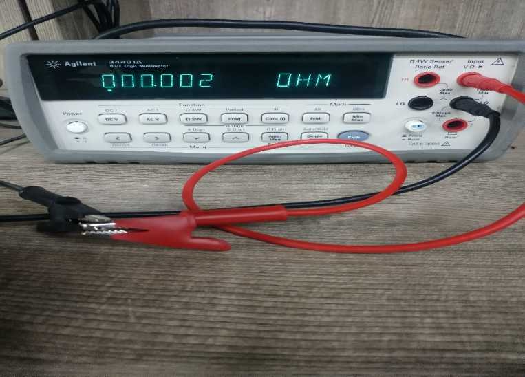
We know that the Multimeter has a shortcut resistance 0.002 ohm.
Step 2: Measure the resistance between the two shorted wires of PT100 Probe.
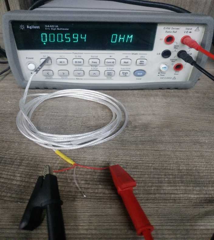
As example, in this step, we check the shorted wire (both red) with 0.594 ohm, So we know that each wire of PT100 has (0.594-0.002)/2=0.296R (Where 0.002 is the value we got from step 1) .
Step 3: Run Calibrate Command.
Run this command to both channels to use 0.296R calibrate resistance.
AT+RCABLE=296,0 --> Calibrate Channel 1 with 0.296R
Or use LoRaWAN downlink command (0xA8 Code) to set: 0xA801280000
User can use 0xA9 downlink command to poll the current calibration value.
Step 4: Connect the PT100 to LTC2
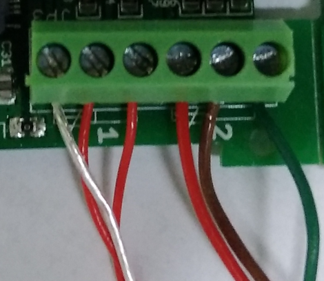
For a 3 wire PT100, there are two wire are shortcut, for example, as per above photo Channel 1, there are two red wire , which are shortcut in PT100, connect them as the photo. The 3rd wire (white wire ) connect to the left pin of Channel -1.
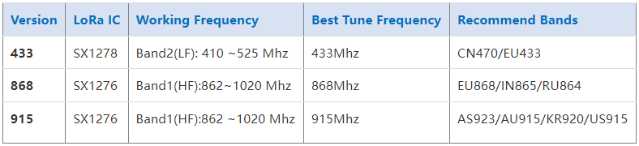
6.3 What is the frequency range of LTC2 LoRa part?
Different LTC2 version supports different frequency range, below is the table for the working frequency and recommend bands for each model:
6.4 How to change the LoRa Frequency Bands/Region
You can follow the instructions for how to upgrade image.
When downloading the images, choose the required image file for download.
6.5 How can I read sensor data without LoRaWAN? For Calibration Purpose
Some clients need to calibrate the sensor value in calibration Lab. In such case, Reading the data without LoRaWAN network is more convenient. To achieve this, use can use a USB-TTL Adapter to connect the LTC2 Motherboard's UART pins while still have the probe connected. See below.
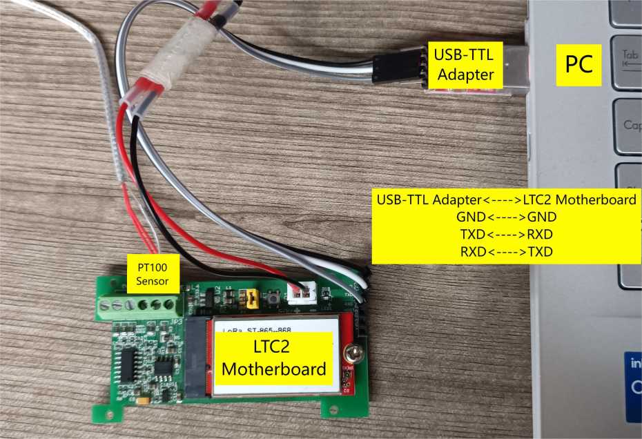
After there is UART Connection, reset the node.
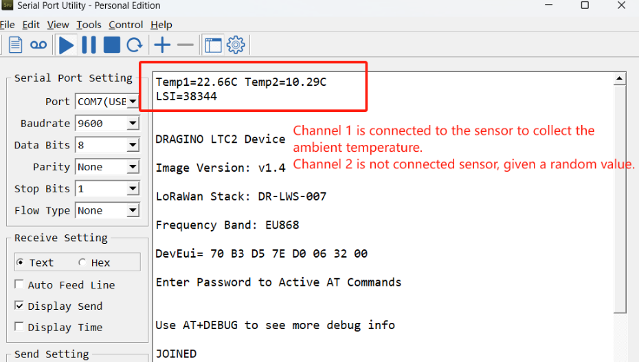
Example output:
6.6 LTC2 supported with 3-wire PT100
The LTC2 uses the bridge method to measure temperature and supports the use of 3-wire PT100.
The difference between the wiring mode of three-wire PT100 and four-wire PT100 and the difference in the detection principle:
- Three wire PT100 adopts bridge method to measure data, and the relationship between the output temperature value and the output value of analog quantity.
- The four-wire PT100 has no bridge, is sent by constant current source, voltmeter measurement, and finally gives the measured resistance value.
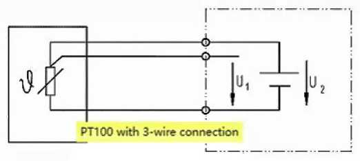
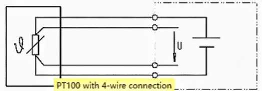
Note: 2-wire PT100, current loop and voltage measurement loop combined in one, poor accuracy, not discussed.
7. Trouble Shooting
7.1 AT Command input doesn't work
In the case if user can see the console output but can't type input to the device. Please check if you already include the ENTER while sending out the command. Some serial tool doesn't send ENTER while press the send key, user need to add ENTER in their string.
8. Order Info
Part Number : LTC2-XXX-YYY
XXX: Probe Version
- SI: Standard IP68 probe x 1
- LT: Low Temperature probe x 1
- HT: High Temperature probe x 1
- FSA: Food Safety probe x 1
- FT: Flat Type probe x 1
- NA: No probe
YYY: The default frequency band
- AS923 : LoRaWAN AS923 band
- AU915 : LoRaWAN AU915 band
- EU433 : LoRaWAN EU433 band
- EU868 : LoRaWAN EU868 band
- KR920 : LoRaWAN KR920 band
- US915 : LoRaWAN US915 band
- IN865 : LoRaWAN IN865 band
- CN470 : LoRaWAN CN470 band
9. Packing Info
Package Includes:
- LTC2 LoRaWAN Temperature Transmitter x 1
Dimension and weight:
- Device Size: cm
- Device Weight: g
- Package Size / pcs : cm
- Weight / pcs : g
10. Support
- Support is provided Monday to Friday, from 09:00 to 18:00 GMT+8. Due to different timezones we cannot offer live support. However, your questions will be answered as soon as possible in the before-mentioned schedule.
- Provide as much information as possible regarding your enquiry (product models, accurately describe your problem and steps to replicate it etc) and send a mail to support@dragino.com.