LHT65N-DC Connection Instruction
Table of Contents:
1.Door sensor
Application: Connect to Door Sensor detect door open / close and send to IoT server
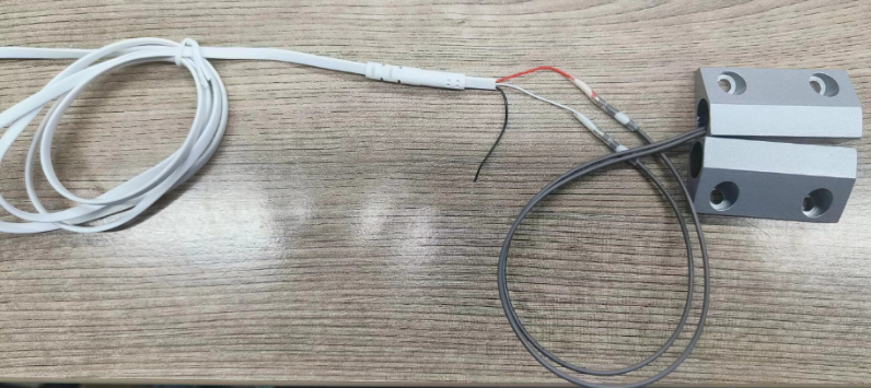
Sensor Type: Normal Close Type Door Sensor as below

1.1 Hardware Connection
LHT65N VDD <--> one wire of Door Sensor
LHT65N Interrupt Pin <--> one wire of Door Sensor
1.2 Software Configuration
Set LHT65N to Interrupt Mode so device will uplink when there is open/close event
AT Command : AT+EXT=4,1
Downlink Command: 0xA20401 : Same as AT+EXT=4,1
Enlarge the TDC time so LHT65N will send Keep Alive message every 12 hours so to save battery life.
AT Command :AT+TDC=43200000
Downlink Command: 0x0100A8C0 Same as AT+TDC=43200000
1.3 Test Result
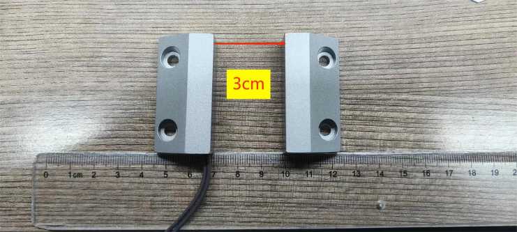
Move the magnet part to generate Open / Close event and check the uplink packet in the platform.

1.4 Power Consumption Notice
Connect a Normal Close Door Sensor won't increase sleep current (~6uA). The power consumption mainly depends on the how many open/close event happen every day.
2. Water Sensor
Application: Connect to Water leakage Sensor detect door open / close and send to IoT server
2.1 Hardware Connection
- LHT65N VDD <--> one wire of water leakage Sensor
- LHT65N Interrupt Pin <--> one wire of water leakage Sensor

2.2 Software Configuration
Set LHT65N to Interrupt Mode so device will uplink when there is open/close event
- AT Command : AT+EXT=4,1
- Downlink Command: 0xA20401 : Same as AT+EXT=4,1
Enlarge the TDC time so LHT65N will send Keep Alive message every 12 hours so to save battery life.
AT Command :AT+TDC=43200000
Downlink Command: 0x0100A8C0 Same as AT+TDC=4320000
2.3 Test Result
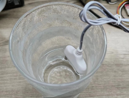
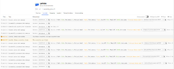
Partial contact of the sensor probe with water generates open/close events and checks for upstream packets in the platform.
2.4 Power Consumption Notice
- Connecting the water leak sensor increases the sleep current (~40uA). When using a water leak sensor, the battery life will be reduced.
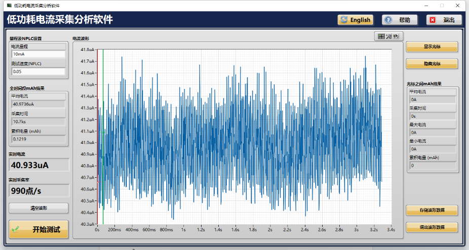
When the probe comes into contact with water, it will increase the low power consumption by about 300uA.
Then when it is out of contact with water, the power consumption will slowly drop. The reason for the slow drop is that there are water beads hanging on the surface of the probe. When it dries, It will reduce power consumption.
3 Smoke Sensor
Application: Mainly suitable for hotels, warehouses, guesthouses, restaurants, hostels, factories, oil field well teams, prefabricated houses and other public places.When it is detected that the smoke in the air reaches a certain concentration value, an alarm signal is triggered immediately. False alarms are likely to occur when dew, oil smoke, water vapor, sudden temperature changes, corrosive gases, strong airflow or air conditioning, or outdoor environments occur.
- Technical Notes:
| Parameter name | Explanation |
|---|---|
| Power | DC 3V(Two 1.5V alkaline batteries) |
| Indicator lights | It will flash once every minute in the monitoring state, and it will stay on when smoke is detected. |
| Working temperature | -10℃~+50℃ |
| Working humidity | ≤95% (Under 40℃ working environment) |
3.1 Hardware Connection
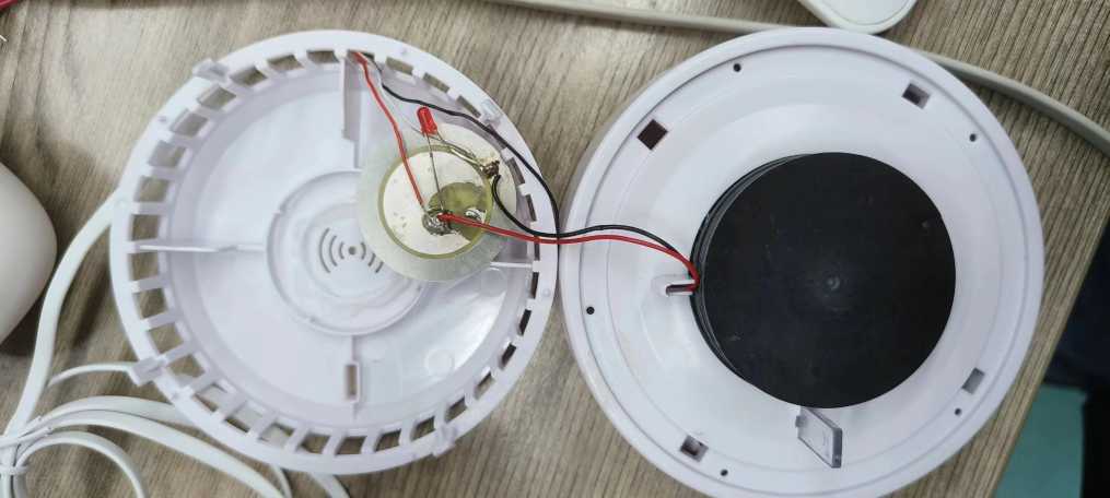
- LHT65N VDD <--> Sound vibration film red line
- LHT65N Interrupt Pin <--> sound vibration film black line
3.2 Software Configuration
Set LHT65N to Interrupt Mode so device will uplink when there is open/close event
- AT Command : AT+EXT=4,1
- Downlink Command: 0xA20401 : Same as AT+EXT=4,1
Enlarge the TDC time so LHT65N will send Keep Alive message every 12 hours so to save battery life.
AT Command :AT+TDC=43200000
Downlink Command: 0x0100A8C0 Same as AT+TDC=4320000
3.3 Test Result
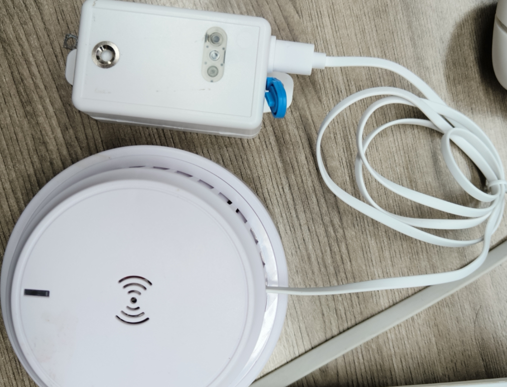

When triggered, the node will send data packets twice. When it is not triggered or the trigger ends, it needs to wait for the TDC time to send data packets.
3.4 Power Consumption Notice
When there is smoke detect, the smoke sensor will be trigger , there will be sound from speaker and trigger the LHT65N to send uplink
4. SOS switch sensor
Application:Connected to the SOS switch, the sensor detects whether an alarm is triggered and sends it to the IoT server.
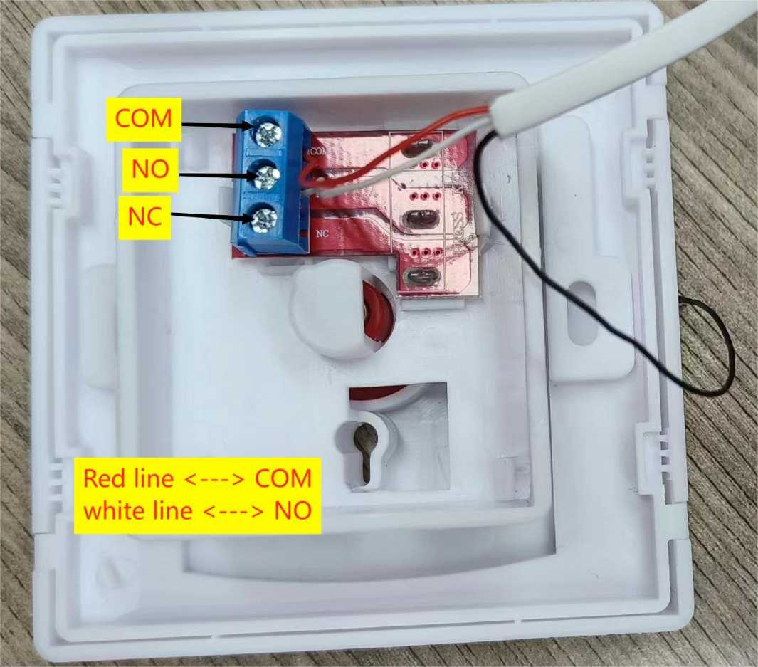
When the red button is pressed, 1 and 2 are connected, and 1 and 3 are disconnected. When you release your hand, the red button automatically pops up, 1 and 2 are disconnected, 1 and 3 are connected, and it automatically resets without a key; This emergency help button is used for emergencies or emergencies. Press this red button to give an alarm and SOS emergency call (COM is 1, NO is 2, NC is 3)
4.1 Hardware Connection
LHT65N VDD <---> COM port of the SOS button
LHT65N Interrupt Pin <--> The NO port of the SOS button
4.2 Software Configuration
Set LHT65N to Interrupt Mode so device will uplink when there is open/close event
- AT Command : AT+EXT=4,1
- Downlink Command: 0xA20401 : Same as AT+EXT=4,1
Enlarge the TDC time so LHT65N will send Keep Alive message every 12 hours so to save battery life.
- AT Command :AT+TDC=86400000
- Downlink Command: 01015180 Same as AT+TDC=86400000
4.3 Test Result
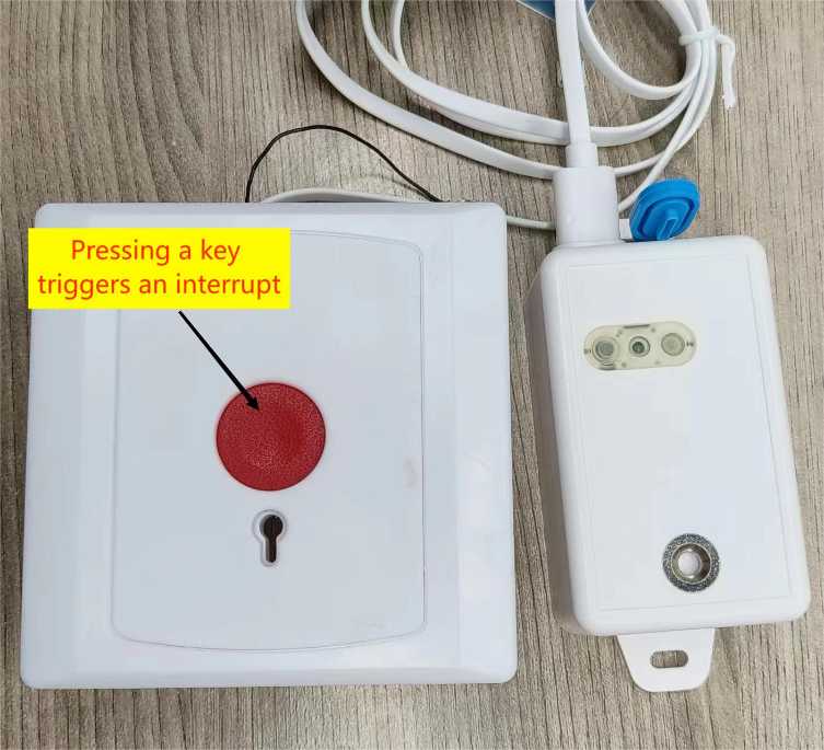
Note: When the LHT65N triggers an interrupt packet, it needs to wait 6s before a new trigger is generated.
When the button is pressed, the SOS button will be triggered, and the LHT65N will also be triggered to send the uplink signal.
4.4 Power Consumption Notice
Connect SOS button Sensor won't increase sleep current (~6uA). The power consumption mainly depends on the how many open/close event happen every day.
5. Flow sensor
Application: It detects water flow volume and uplink to IoT server via LoRaWAN network. User can use this to monitor the water usage for buildings.
5.1 Hardware Connection
LHT65N VDD <---> Flow sensor red line
LHT65N Interrupt Pin <--> Flow sensor Signal line
LHT65N GND <---> Flow sensor black line(Note: If the sensor does not need power supply, please connect the red line (rising edge trigger) or the black line (falling edge trigger) as needed.)

5.2 Software Configuration
Note: Because the traffic sensor is a counting sensor, the node can only be set in counting mode.
Set LHT65N to Counting Mode so device will uplink when there is open/close event
- AT Command : AT+EXT=8,1
- Downlink Command: 0xA2080101 : Same as AT+EXT=8,1
Enlarge the TDC time so LHT65N will send Keep Alive message every 12 hours so to save battery life.
AT Command :AT+TDC=43200000
Downlink Command: 0x0100A8C0 Same as AT+TDC=4320000
5.3 Test Result

When the water passes through the flow sensor, the cumulative count will be generated (note: when installing the flow sensor, it is necessary to pay attention to the inlet direction of the installation).

5.4 Power Consnmption Notice
Connect Flow Sensor won't increase sleep current (~6uA). The power consumption mainly depends on the how many counting event happen every day.