LDDS04 - LoRaWAN 4-Channels Distance Detection Sensor User Manual
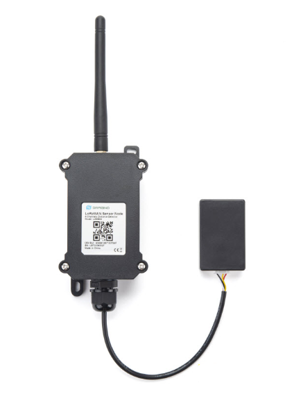
Table of Contents:
- 1. Introduction
- 2. Configure LDDS04 to connect to LoRaWAN network
- 3. Configure LDDS04 via AT Command or LoRaWAN Downlink
- 4. Battery & Power Consumption
- 5. Use AT Command
- 6. FAQ
- 7. Trouble Shooting
- 8. Order Info
- 9. Packing Info
- 10. Support
1. Introduction
1.1 What is LoRaWAN 4-Channels Distance Sensor
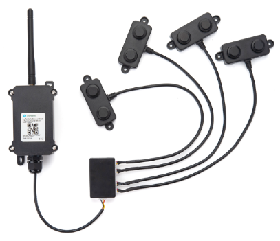
The Dragino LDDS04 is a LoRaWAN 4-Channels Distance Sensor for Internet of Things solution. It is capable to add up to four Ultrasonic Sensors to measure four distances at the same time.
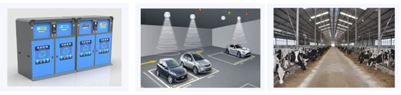
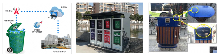
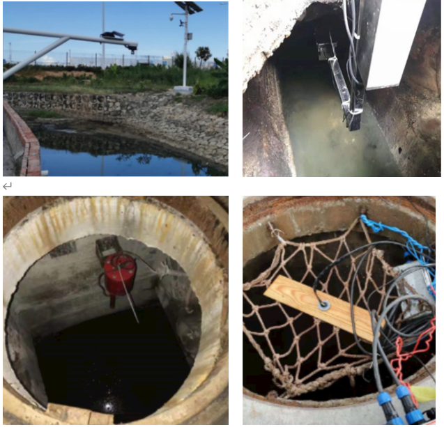
The LDDS04 can be applied to scenarios such as horizontal distance measurement, parking management system, object proximity and presence detection, intelligent trash can management system, robot obstacle avoidance, automatic control, sewer, etc.
It detects the distance between the measured object and the sensor, and uploads the value via wireless to LoRaWAN IoT Server.
The LoRa wireless technology used in LDDS04 allows device to send data and reach extremely long ranges at low data-rates. It provides ultra-long range spread spectrum communication and high interference immunity whilst minimizing current consumption.
LDDS04 is powered by 8500mAh Li-SOCI2 battery, it is designed for long term use up to 5 years.
Each LDDS04 is pre-load with a set of unique keys for LoRaWAN registrations, register these keys to local LoRaWAN server and it will auto connect after power on.
1.2 Features
- LoRaWAN 1.0.3 Class A
- Ultra-low power consumption
- Detect Range: Base on External Probe
- Monitor Battery Level
- Bands: CN470/EU433/KR920/US915/EU868/AS923/AU915/IN865
- AT Commands to change parameters
- Uplink on periodically
- Downlink to change configure
- 8500mAh Battery for long term use
1.3 Applications
- Horizontal distance measurement
- Parking management system
- Object proximity and presence detection
- Intelligent trash can management system
- Robot obstacle avoidance
- Automatic control
- Sewer
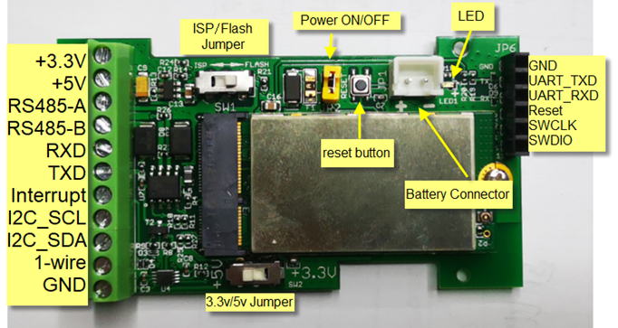
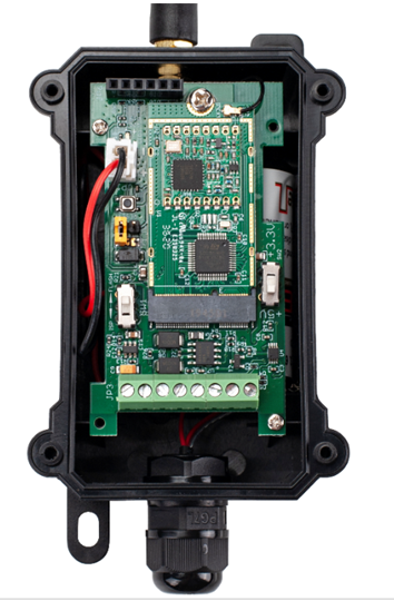
1.4 Pin mapping and power on
1.5 Probe Options
1.5.1 Probes Comparation
| Model | Photo | Description |
|---|---|---|
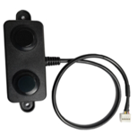
| A01A-15 |
| Detect Distance: 28 cm ~ 750 cm Bling Spot Distance: 0 ~ 28cm Accuracy: ±(1cm+S*0.3%) (S: Distance) Measure Angle: ~ 40° Cable Length: 1.5 meter Temperature Compensation Suitable for Flat Object Detect IP67 Water Proof |
| A02-15 |
| Detect Distance: 3cm ~ 450cm Bling Spot Distance: 0 ~ 3cm Accuracy: ±(1cm+S*0.3%) (S: Distance) Measure Angle: ~ 60° Cable Length: 1.5 meter Temperature Compensation Suitable for Flat Object Detect, Rubbish Bin IP67 Water Proof |
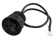
| A13-15 |
| Detect Distance: 25cm ~ 200cm Bling Spot Distance: 0 ~ 25cm Accuracy: ±(1cm+S*0.3%) (S: Distance) Measure Angle: ~ 20° Cable Length: 1.5 meter Temperature Compensation Suitable for Flat Object Detect, Rubbish Bin IP67 Water Proof |
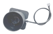
| A16-15 |
| Detect Distance: 50cm ~ 1500cm Bling Spot Distance: 0 ~ 50cm Accuracy: ±(1cm+S*0.3%) (S: Distance) Measure Angle: ~ 40° Cable Length: 1.5 meter Temperature Compensation Suitable for Long Distance Detect IP67 Water Proof |
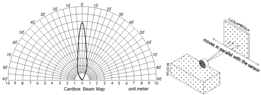
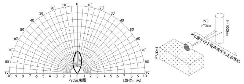
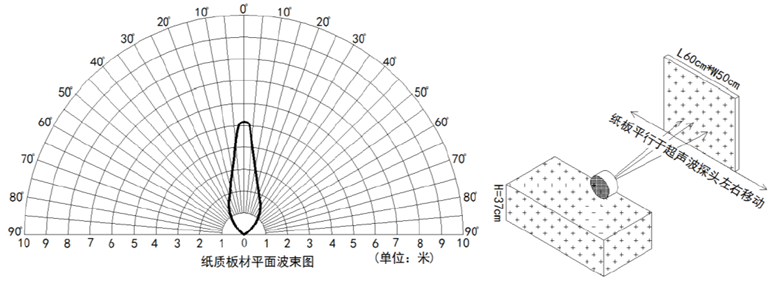
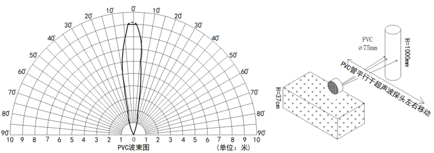
1.5.2 P01A-15 probe
A01A-15 is mainly used for plane distance measurement; it can carry out targeted measurement on plane objects and can measure long distances and high accuracy.
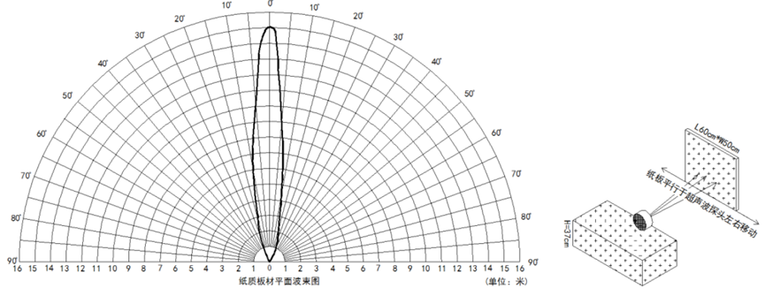
Beam Chart:
(1) The tested object is a white cylindrical tube made of PVC, with a height of 100cm and a diameter of 7.5cm.
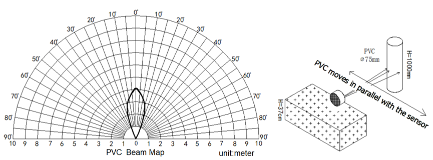
(2) The object to be tested is a "corrugated cardboard box" perpendicular to the central axis of 0 °, and the length * width is 60cm * 50cm.
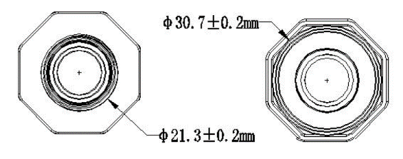
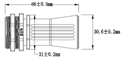
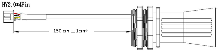
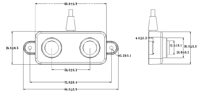
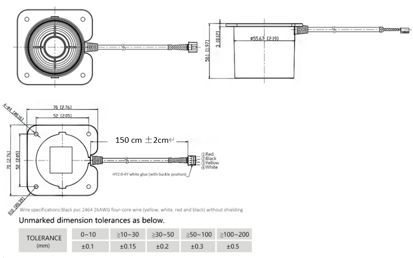
Mechanical:
Application:
1.5.3 A02-15 probe
Beam Chart:
(1) The tested object is a white cylindrical tube made of PVC, with a height of 100cm and a diameter of 7.5cm.
(2) The object to be tested is a "corrugated cardboard box" perpendicular to the central axis of 0 °, and the length * width is 60cm * 50cm.
Mechanical:
Application:
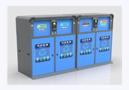
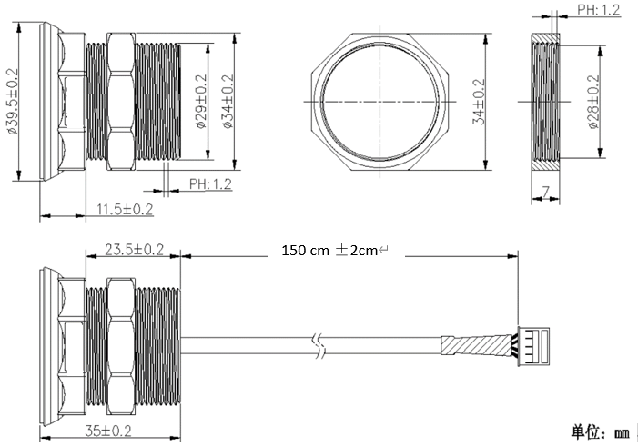
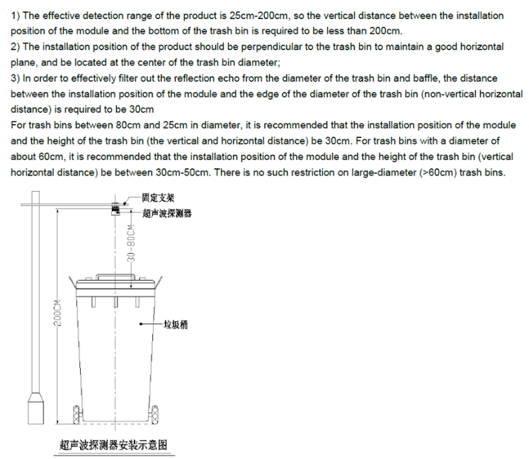
1.5.4 A13-15 probe
Beam Chart:
(1) The tested object is a white cylindrical tube made of PVC, with a height of 100cm and a diameter of 7.5cm.
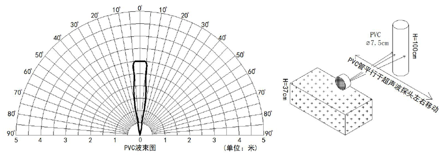
(2) The object to be tested is a "corrugated cardboard box" perpendicular to the central axis of 0 °, and the length * width is 60cm * 50cm.
Mechanical:
Installation Requirement:
Application:
1.5.5 A13-16 probe
Beam Chart:
(1) The tested object is a white cylindrical tube made of PVC, with a height of 100cm and a diameter of 7.5cm.
(2) The object to be tested is a "corrugated cardboard box" perpendicular to the central axis of 0 °, and the length * width is 60cm * 50cm.
Mechanical:
Application:
2. Configure LDDS04 to connect to LoRaWAN network
2.1 How it works
The LDDS04 is configured as LoRaWAN OTAA Class A mode by default. It has OTAA keys to join LoRaWAN network. To connect a local LoRaWAN network, you need to input the OTAA keys in the LoRaWAN IoT server and power on the LDDS04. It will automatically join the network via OTAA and start to send the sensor value. The default uplink interval is 20 minutes.
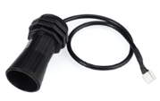
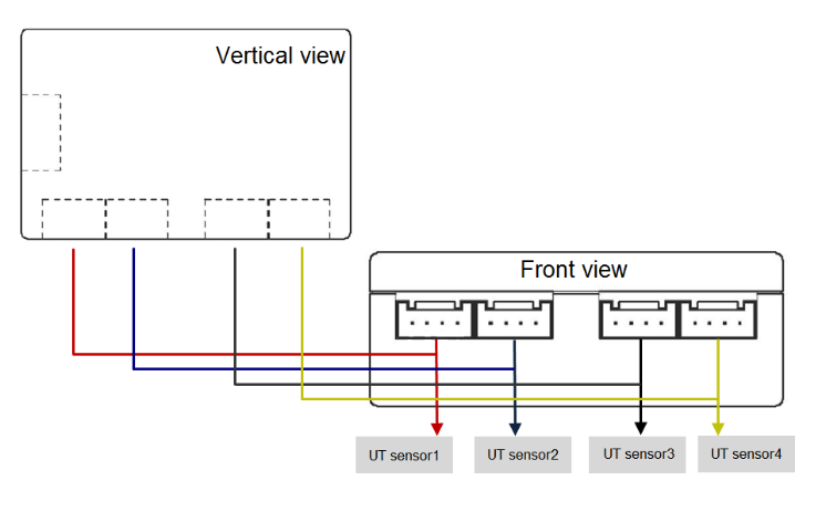
2.2 Connect Probe
LDDS04 has a converter, User need to connect the Ultrasonic Probes to the convert as below. Different probes are supported, please see this link for the probe options.
Probe mapping as below.
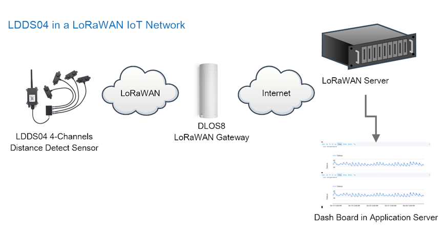
2.3 Quick guide to connect to LoRaWAN server (OTAA)
Below is the network structure; we use the DLOS8 as a LoRaWAN gateway in this example.
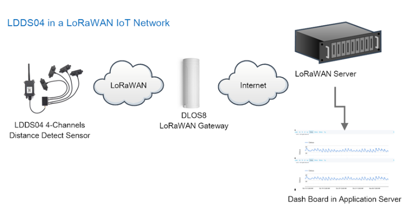
The DLOS8 is already set to connected to TTN network , so what we need to now is configure the TTN server.
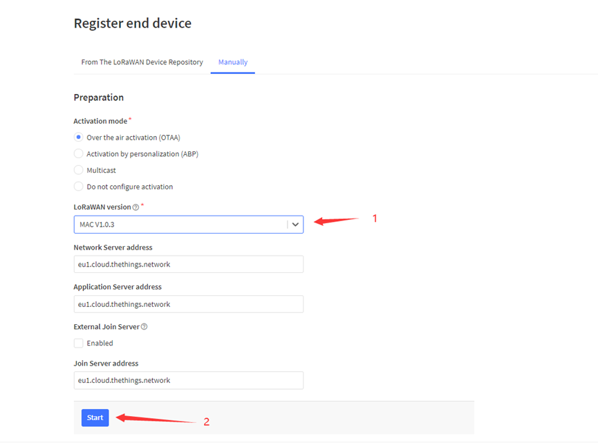
Step 1: Create a device in TTN with the OTAA keys from LDDS04.
Each LDDS04 is shipped with a sticker with the default device keys, user can find this sticker in the box. it looks like below:
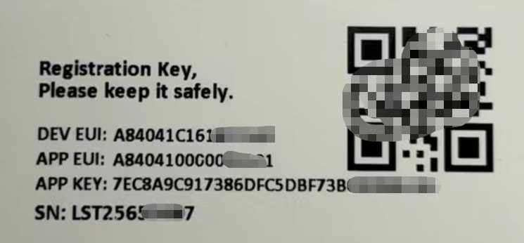
You can enter this key in the LoRaWAN Server portal. Below is TTN screen shot:
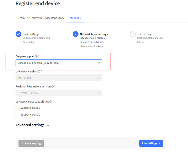
Register the device:
Add APP EUI and DEV EUI:
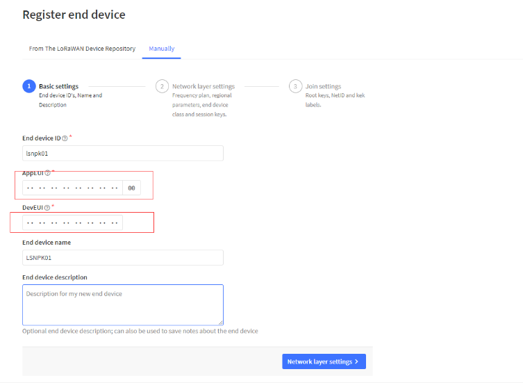
Add APP EUI in the application:
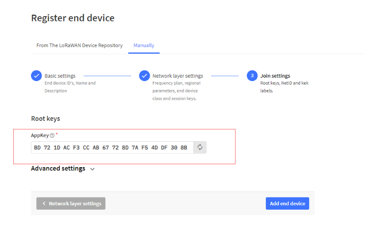
Add APP KEY
Step 2: Power on LDDS04
Put a Jumper on JP2 to power on the device. ( The Switch must be in FLASH position).
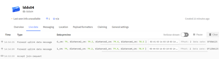
Step 3: The LDDS04 will auto join to the TTN network. After join success, it will start to upload messages to TTN and you can see the messages in the panel.

2.4 Uplink Payload
LDDS04 will uplink payload via LoRaWAN with below payload format:
Uplink payload includes in total 11 bytes.
Size(bytes) | 2 | 2 | 2 | 2 | 2 | 1 |
|---|---|---|---|---|---|---|
| Value |
2.4.1 Battery Info
Check the battery voltage for LDDS04.
Ex1: 0x0B45 = 2885mV
Ex2: 0x0B49 = 2889mV
2.4.2 Interrupt Pin
This data field shows if this packet is generated by interrupt or not. Click here for the hardware and software set up.
Note: The Internet Pin is a separate pin in the screw terminal. See pin mapping.
Example:
(0x0D4A & 0x8000) >>15 = 0: Normal uplink packet.
(0x8D41 & 0x8000) >>15 = 1: Interrupt Uplink Packet.
2.4.3 Distance
The measuring distance of the four distance measuring modules, the default unit is cm.
Example:
Uplink Payload: 0D 4A 03 16 03 18 03 1A 03 15 01
Data analysis:
Distance of UT sensor1 : 0316(H) = 790 (D)/10 = 79cm.
Distance of UT sensor2 : 0318(H) = 792 (D)/10 = 79.2cm.
Distance of UT sensor3 : 031A(H) = 794 (D)/10 = 79.4cm.
Distance of UT sensor4 : 0315(H) = 789 (D)/10 = 78.9cm.
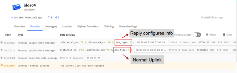
2.4.4 Message Type
For a normal uplink payload, the message type is always 0x01.
Valid Message Type:
| Message Type Code | Description | Payload |
|---|---|---|
| 0x01 | Normal Uplink | Normal Uplink Payload |
| 0x02 | Reply configures info | Configure Info Payload |
2.4.5 Decode payload in The Things Network
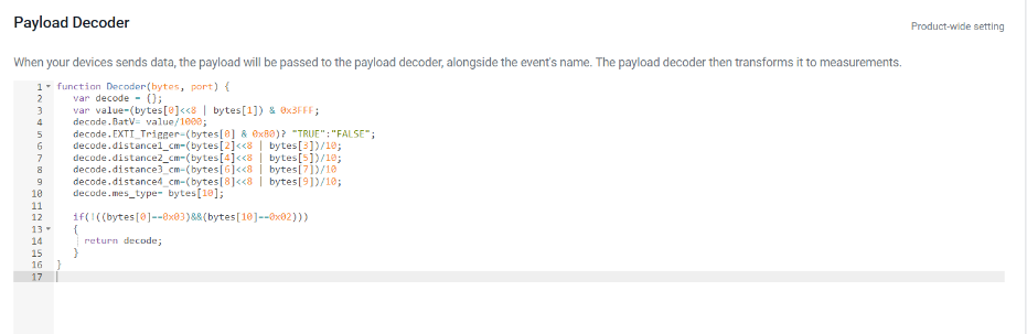
While using TTN network, you can add the payload format to decode the payload.
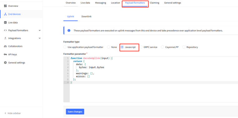
The payload decoder function for TTN is here:
LDDS04 TTN Payload Decoder: ttps://github.com/dragino/dragino-end-node-decoder
function Decoder(bytes, port) {
var decode = {};
var value=(bytes[0]<<8 | bytes[1]) & 0x3FFF;
decode.BatV= value/1000;
decode.EXTI_Trigger=(bytes[0] & 0x80)? "TRUE":"FALSE";
decode.distance1_cm=(bytes[2]<<8 | bytes[3])/10;
decode.distance2_cm=(bytes[4]<<8 | bytes[5])/10;
decode.distance3_cm=(bytes[6]<<8 | bytes[7])/10
decode.distance4_cm=(bytes[8]<<8 | bytes[9])/10;
decode.mes_type= bytes[10];
if(!((bytes[0]==0x03)&&(bytes[10]==0x02)))
{
return decode;
}
}
2.5 Uplink Interval
The LDDS04 by default uplink the sensor data every 20 minutes. User can change this interval by AT Command or LoRaWAN Downlink Command. See this link: Change Uplink Interval
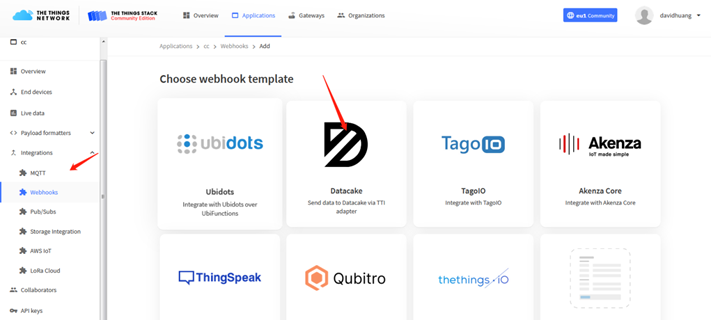
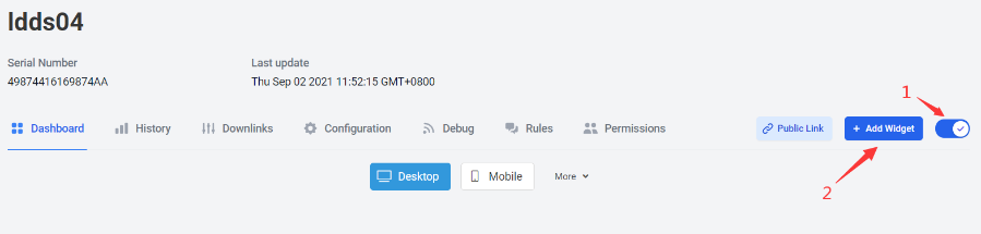
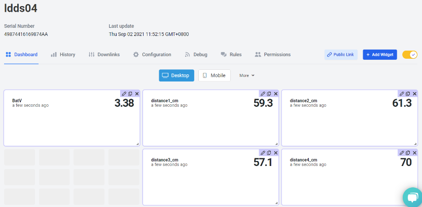
2.6 Show Data in DataCake IoT Server
DATACAKE provides a human friendly interface to show the sensor data, once we have data in TTN, we can use DATACAKE to connect to TTN and see the data in DATACAKE. Below are the steps:
Step 1: Be sure that your device is programmed and properly connected to the network at this time.
Step 2: To configure the Application to forward data to DATACAKE you will need to add integration. To add the DATACAKE integration, perform the following steps:
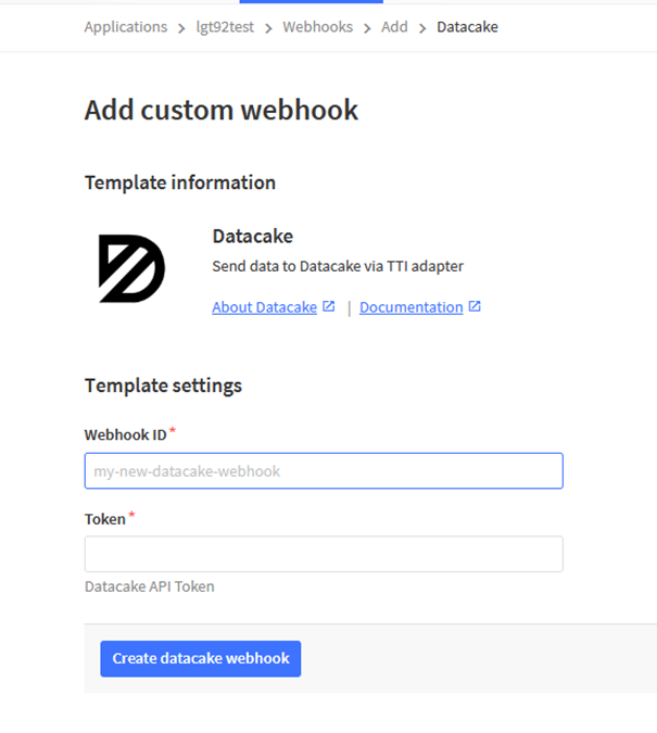
Step 3: Create an account or log in Datacake.
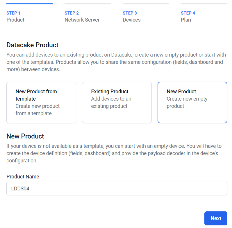
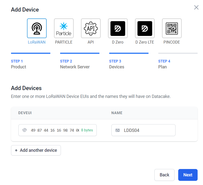
Step 4: Create LDDS04 product.
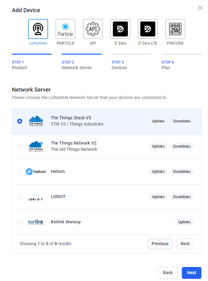
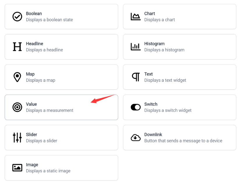
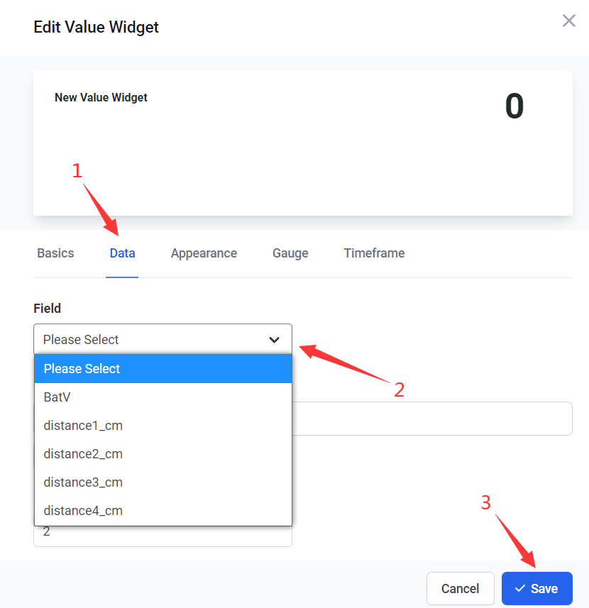
Step 5: add payload decode
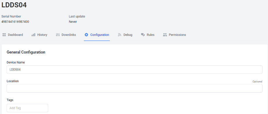
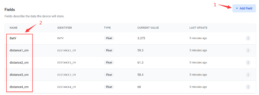
After added, the sensor data arrive TTN, it will also arrive and show in Datacake.
2.7 Frequency Plans
The LDDS04 uses OTAA mode and below frequency plans by default. If user want to use it with different frequency plan, please refer the AT command sets.
2.7.1 EU863-870 (EU868)
Uplink:
868.1 - SF7BW125 to SF12BW125
868.3 - SF7BW125 to SF12BW125 and SF7BW250
868.5 - SF7BW125 to SF12BW125
867.1 - SF7BW125 to SF12BW125
867.3 - SF7BW125 to SF12BW125
867.5 - SF7BW125 to SF12BW125
867.7 - SF7BW125 to SF12BW125
867.9 - SF7BW125 to SF12BW125
868.8 - FSK
Downlink:
Uplink channels 1-9 (RX1)
869.525 - SF9BW125 (RX2 downlink only)
2.7.2 US902-928(US915)
Used in USA, Canada, and South America. Frequency band as per definition in LoRaWAN 1.0.3 Regional document.
To make sure the end node supports all sub band by default. In the OTAA Join process, the end node will use frequency 1 from sub-band1, then frequency 1 from sub-band2, then frequency 1 from sub-band3, etc to process the OTAA join.
After Join success, the end node will switch to the correct sub band by:
Check what sub-band the LoRaWAN server ask from the OTAA Join Accept message and switch to that sub-band
Use the Join successful sub-band if the server doesn't include sub-band info in the OTAA Join Accept message ( TTN v2 doesn't include)
2.7.3 CN470-510 (CN470)
Used in China, Default use CHE=1
Uplink:
486.3 - SF7BW125 to SF12BW125
486.5 - SF7BW125 to SF12BW125
486.7 - SF7BW125 to SF12BW125
486.9 - SF7BW125 to SF12BW125
487.1 - SF7BW125 to SF12BW125
487.3 - SF7BW125 to SF12BW125
487.5 - SF7BW125 to SF12BW125
487.7 - SF7BW125 to SF12BW125
Downlink:
506.7 - SF7BW125 to SF12BW125
506.9 - SF7BW125 to SF12BW125
507.1 - SF7BW125 to SF12BW125
507.3 - SF7BW125 to SF12BW125
507.5 - SF7BW125 to SF12BW125
507.7 - SF7BW125 to SF12BW125
507.9 - SF7BW125 to SF12BW125
508.1 - SF7BW125 to SF12BW125
505.3 - SF12BW125 (RX2 downlink only)
2.7.4 AU915-928(AU915)
Frequency band as per definition in LoRaWAN 1.0.3 Regional document.
To make sure the end node supports all sub band by default. In the OTAA Join process, the end node will use frequency 1 from sub-band1, then frequency 1 from sub-band2, then frequency 1 from sub-band3, etc to process the OTAA join.
After Join success, the end node will switch to the correct sub band by:
Check what sub-band the LoRaWAN server ask from the OTAA Join Accept message and switch to that sub-band
Use the Join successful sub-band if the server doesn't include sub-band info in the OTAA Join Accept message ( TTN v2 doesn't include)
2.7.5 AS920-923 & AS923-925 (AS923)
Default Uplink channel:
923.2 - SF7BW125 to SF10BW125
923.4 - SF7BW125 to SF10BW125
Additional Uplink Channel:
(OTAA mode, channel added by JoinAccept message)
AS920~AS923 for Japan, Malaysia, Singapore:
922.2 - SF7BW125 to SF10BW125
922.4 - SF7BW125 to SF10BW125
922.6 - SF7BW125 to SF10BW125
922.8 - SF7BW125 to SF10BW125
923.0 - SF7BW125 to SF10BW125
922.0 - SF7BW125 to SF10BW125
AS923 ~ AS925 for Brunei, Cambodia, Hong Kong, Indonesia, Laos, Taiwan, Thailand, Vietnam:
923.6 - SF7BW125 to SF10BW125
923.8 - SF7BW125 to SF10BW125
924.0 - SF7BW125 to SF10BW125
924.2 - SF7BW125 to SF10BW125
924.4 - SF7BW125 to SF10BW125
924.6 - SF7BW125 to SF10BW125
Downlink:
Uplink channels 1-8 (RX1)
923.2 - SF10BW125 (RX2)
2.7.6 KR920-923 (KR920)
Default channel:
922.1 - SF7BW125 to SF12BW125
922.3 - SF7BW125 to SF12BW125
922.5 - SF7BW125 to SF12BW125
Uplink: (OTAA mode, channel added by JoinAccept message)
922.1 - SF7BW125 to SF12BW125
922.3 - SF7BW125 to SF12BW125
922.5 - SF7BW125 to SF12BW125
922.7 - SF7BW125 to SF12BW125
922.9 - SF7BW125 to SF12BW125
923.1 - SF7BW125 to SF12BW125
923.3 - SF7BW125 to SF12BW125
Downlink:
Uplink channels 1-7(RX1)
921.9 - SF12BW125 (RX2 downlink only; SF12BW125 might be changed to SF9BW125)
2.7.7 IN865-867 (IN865)
Uplink:
865.0625 - SF7BW125 to SF12BW125
865.4025 - SF7BW125 to SF12BW125
865.9850 - SF7BW125 to SF12BW125
Downlink:
Uplink channels 1-3 (RX1)
866.550 - SF10BW125 (RX2)
2.8 LED Indicator
The LDDS04 has an internal LED which is used to show the status of different state.
- After LDDS04 is turned on, if the 4 channels converter is detected, the LED will flash 4 times quickly.
- Blink once when device transmit a packet.
- Solid ON for Five Seconds when OTAA Join Successfully.
2.9 Firmware Change Log
Firmware download link: https://www.dropbox.com/sh/q25x7twbj031usi/AAAkI5LmJYIqdnDkYvHjiLyba?dl=0
Firmware Upgrade Method: Firmware Upgrade Instruction
3. Configure LDDS04 via AT Command or LoRaWAN Downlink
Use can configure LDDS04 via AT Command or LoRaWAN Downlink.
AT Command Connection: See FAQ.
LoRaWAN Downlink instruction for different platforms: IoT LoRaWAN Server
There are two kinds of commands to configure LDDS04, they are:
General Commands.
These commands are to configure:
General system settings like: uplink interval.
LoRaWAN protocol & radio related command.
They are same for all Dragino Device which support DLWS-005 LoRaWAN Stack. These commands can be found on the wiki: End Device AT Commands and Downlink Command
Commands special design for LDDS04
These commands only valid for LDDS04, as below:
3.1 Set Transmit Interval Time
Feature: Change LoRaWAN End Node Transmit Interval.
AT Command: AT+TDC
| Command Example | Function | Response |
|---|---|---|
| AT+TDC=? | Show current transmit Interval | 30000 |
| AT+TDC=60000 | Set Transmit Interval | OK |
Downlink Command: 0x01
Format: Command Code (0x01) followed by 3 bytes time value.
If the downlink payload=0100003C, it means set the END Node's Transmit Interval to 0x00003C=60(S), while type code is 01.
- Example 1: Downlink Payload: 0100001E // Set Transmit Interval (TDC) = 30 seconds
- Example 2: Downlink Payload: 0100003C // Set Transmit Interval (TDC) = 60 seconds
3.2 Set Interrupt Mode
Feature, Set Interrupt mode for GPIO_EXIT.
Downlink Command: AT+INTMOD
| Command Example | Function | Response |
|---|---|---|
| AT+INTMOD=? | Show current interrupt mode | 0 |
| AT+INTMOD=2 | Set Transmit Interval | OK |
Downlink Command: 0x06
Format: Command Code (0x06) followed by 3 bytes.
This means that the interrupt mode of the end node is set to 0x000003=3 (rising edge trigger), and the type code is 06.
Example 1: Downlink Payload: 06000000 // Turn off interrupt mode
Example 2: Downlink Payload: 06000003 // Set the interrupt mode to rising edge trigger
3.3 Get Firmware Version Info
Feature: use downlink to get firmware version.
Downlink Command: 0x26
| Downlink Control Type | FPort | Type Code | Downlink payload size(bytes) |
| Get Firmware Version Info | Any | 26 | 2 |
- Reply to the confirmation package: 26 01
- Reply to non-confirmed packet: 26 00
Device will send an uplink after got this downlink command. With below payload:
Configures info payload:
Size(bytes) | 1 | 1 | 1 | 2 | 1 | 4 | 1 |
|---|---|---|---|---|---|---|---|
| Value | Software Type | Frequency | Sub-band | Firmware | Sensor Type | Reserve | Message Type |
Software Type: Always 0x03 for LDDS04
Frequency Band:
0x01: EU868
0x02: US915
0x03: IN865
0x04: AU915
0x05: KZ865
0x06: RU864
0x07: AS923
0x08: AS923-1
0x09: AS923-2
0xa0: AS923-3
Sub-Band: value 0x00 ~ 0x08
Firmware Version: 0x0100, Means: v1.0.0 version
Sensor Type:
0x01: LSE01
0x02: LDDS75
0x03: LDDS20
0x04: LLMS01
0x05: LSPH01
0x06: LSNPK01
0x07: LLDS12
4. Battery & Power Consumption
LDDS04 uses ER26500 + SPC1520 battery pack. See below link for detail information about the battery info and how to replace.
Battery Info & Power Consumption Analyze .
5. Use AT Command
5.1 Access AT Commands
LDDS04 supports AT Command set in the stock firmware. You can use a USB to TTL adapter to connect to LDDS04 for using AT command, as below.
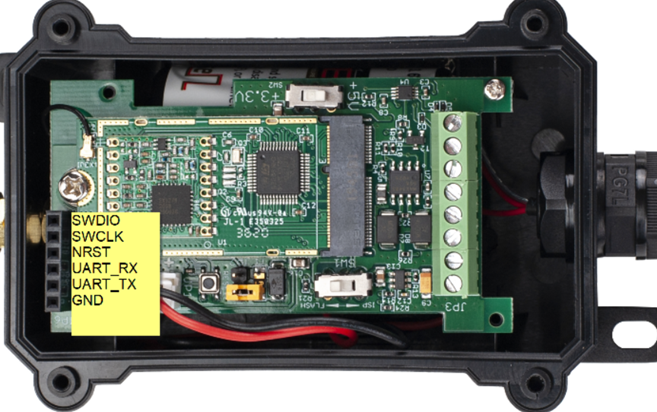
Connection:
USB TTL GND <----> GND
USB TTL TXD <----> UART_RXD
USB TTL RXD <----> UART_TXD
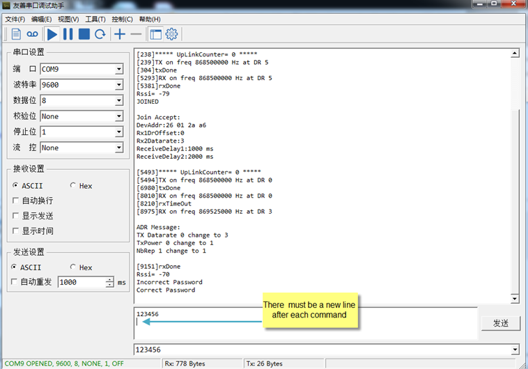
In the PC, you need to set the serial baud rate to 9600 to access the serial console for LDDS04.
LDDS04 will output system info once power on as below:
Valid AT Command please check Configure Device.
6. FAQ
6.1 How to change the LoRa Frequency Bands/Region
You can follow the instructions for how to upgrade image.
When downloading the images, choose the required image file for download.
7. Trouble Shooting
7.1 AT Command input doesn't work
In the case if user can see the console output but can't type input to the device. Please check if you already include the ENTER while sending out the command. Some serial tool doesn't send ENTER while press the send key, user need to add ENTER in their string.
8. Order Info
8.1 Main Device LDDS04
Part Number : LDDS04-XX
XX: The default frequency band
- AS923 : LoRaWAN AS923 band
- AU915 : LoRaWAN AU915 band
- EU433 : LoRaWAN EU433 band
- EU868 : LoRaWAN EU868 band
- KR920 : LoRaWAN KR920 band
- US915 : LoRaWAN US915 band
- IN865 : LoRaWAN IN865 band
- CN470 : LoRaWAN CN470 band
8.2 Probe Model
Detail See Probe Option Section
- A01A-15
- A02-15
- A13-15
- A16-15
9. Packing Info
Package Includes:
- LDDS04 LoRaWAN 4-Channels Distance Sensor x 1
Dimension and weight:
- Device Size: cm
- Device Weight: g
- Package Size / pcs : cm
- Weight / pcs : g
10. Support
- Support is provided Monday to Friday, from 09:00 to 18:00 GMT+8. Due to different timezones we cannot offer live support. However, your questions will be answered as soon as possible in the before-mentioned schedule.
- Provide as much information as possible regarding your enquiry (product models, accurately describe your problem and steps to replicate it etc) and send a mail to support@dragino.com.