LA66 USB LoRaWAN Adapter User Manual
Table of Contents:
- 1. LA66 USB LoRaWAN Adapter
- 1.1 Overview
- 1.2 Features
- 1.3 Specification
- 1.4 Pin Mapping & LED
- 1.5 Example: Send & Get Messages via LoRaWAN in PC
- 1.6 Example: How to join helium
- 1.7 Example: Send PC's CPU/RAM usage to TTN via python
- 1.8 Example: Send & Get Messages via LoRaWAN in RPi
- 1.9 Example: Use of LA66 USB LoRaWAN Adapter and mobile APP
- 1.10 Upgrade Firmware of LA66 USB LoRaWAN Adapter
- 2. FAQ
- 3. Order Info
- 4. Reference
- 5. FCC Statement
1. LA66 USB LoRaWAN Adapter
1.1 Overview
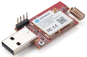
LA66 USB LoRaWAN Adapter is designed to fast turn USB devices to support LoRaWAN wireless features. It combines a CP2101 USB TTL Chip and LA66 LoRaWAN module which can easy to add LoRaWAN wireless feature to PC / Mobile phone or an embedded device that has USB Interface.
LA66 is a ready-to-use module that includes the LoRaWAN v1.0.3 protocol. The LoRaWAN stack used in LA66 is used in more than 1 million LoRaWAN End Devices deployed world widely. This mature LoRaWAN stack greatly reduces the risk to make stable LoRaWAN Sensors to support different LoRaWAN servers and different countries' standards. External MCU can use AT command to call LA66 and start to transmit data via the LoRaWAN protocol.
Each LA66 module includes a world-unique OTAA key for LoRaWAN registration.
Besides the support of the LoRaWAN protocol, LA66 also supports open-source peer-to-peer LoRa Protocol for the none-LoRaWAN application.
LA66 is equipped with TCXO crystal which ensures the module can achieve stable performance in extreme temperatures.
1.2 Features
- LoRaWAN USB adapter base on LA66 LoRaWAN module
- Ultra-long RF range
- Support LoRaWAN v1.0.3 protocol
- Support peer-to-peer protocol
- TCXO crystal to ensure RF performance on low temperature
- Spring RF antenna
- Available in different frequency LoRaWAN frequency bands.
- World-wide unique OTAA keys.
- AT Command via UART-TTL interface
- Firmware upgradable via UART interface
- Open Source Mobile App for LoRaWAN signal detect and GPS tracking.
1.3 Specification
- CPU: 32-bit 48 MHz
- Flash: 256KB
- RAM: 64KB
- Input Power Range: 5v
- Frequency Range: 150 MHz ~ 960 MHz
- Maximum Power +22 dBm constant RF output
- High sensitivity: -148 dBm
- Temperature:
- Storage: -55 ~ +125℃
- Operating: -40 ~ +85℃
- Humidity:
- Storage: 5 ~ 95% (Non-Condensing)
- Operating: 10 ~ 95% (Non-Condensing)
- LoRa Tx Current: <90 mA at +17 dBm, 108 mA at +22 dBm
- LoRa Rx current: <9 mA
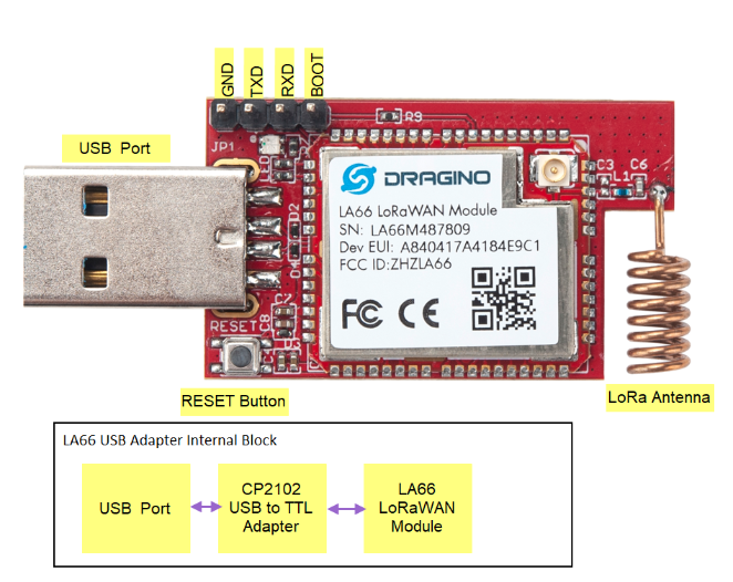
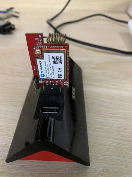
1.4 Pin Mapping & LED
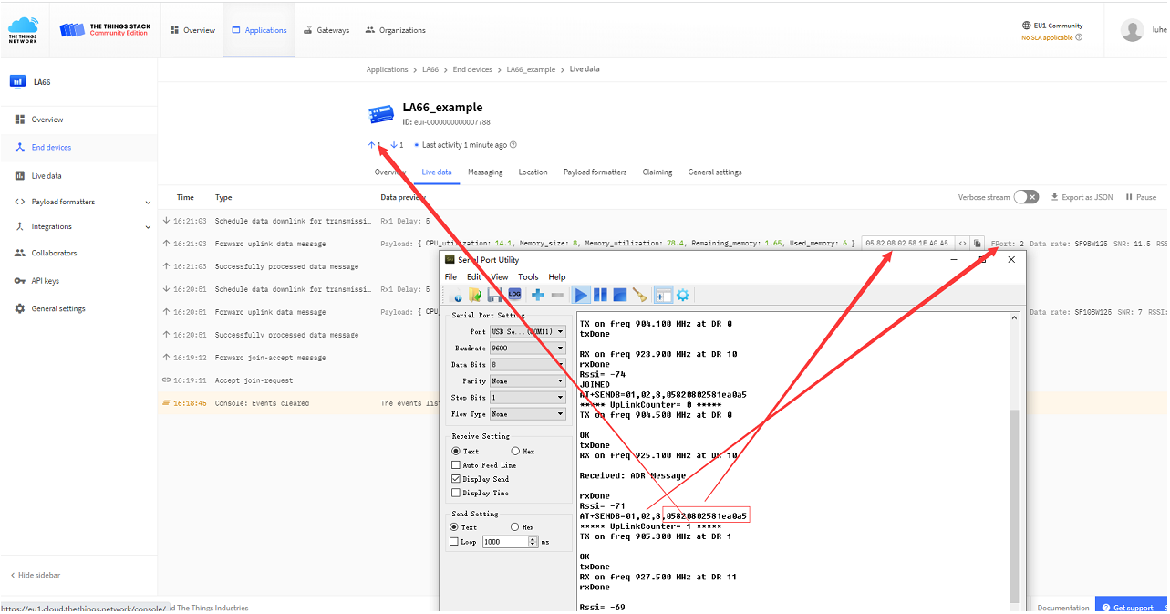
1.5 Example: Send & Get Messages via LoRaWAN in PC
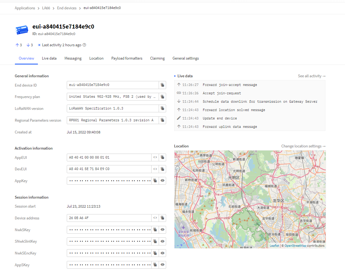
Assume user already input the LA66 USB LoRaWAN Adapter OTAA Keys in TTN and there is already TTN network coverage.
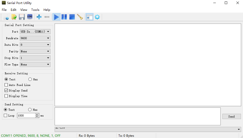
1. Connect the LA66 USB LoRaWAN adapter to PC
Open the serial port tool
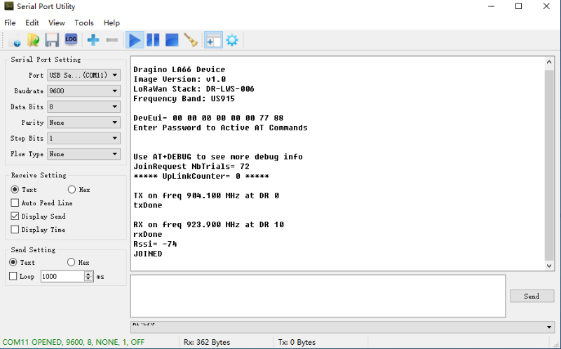
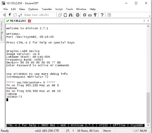
2. Press the reset switch RST on the LA66 USB LoRaWAN Adapter to reset it.
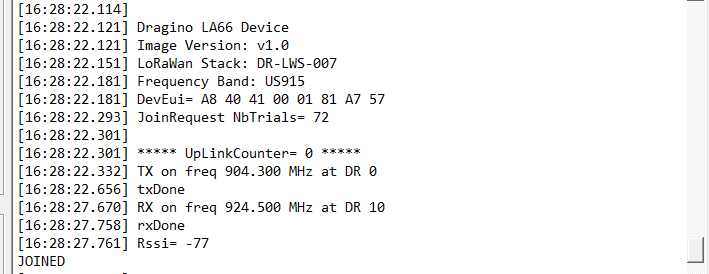
The following picture appears to prove that the LA66 USB LoRaWAN Adapter successfully Join the LoRaWAN network
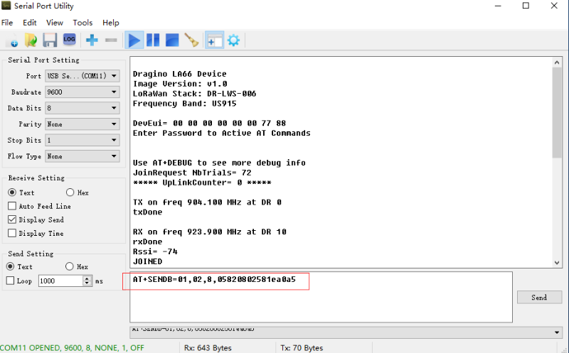
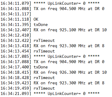
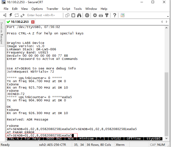
3. See Uplink Command
Command format: AT+SENDB=<confirn_status>,<Fport>,<data_len>,<data>
example: AT+SENDB=01,02,8,05820802581ea0a5
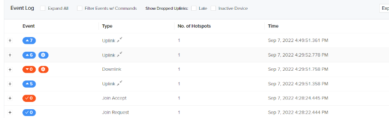
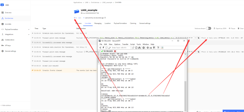
4. Check to see if TTN received the message
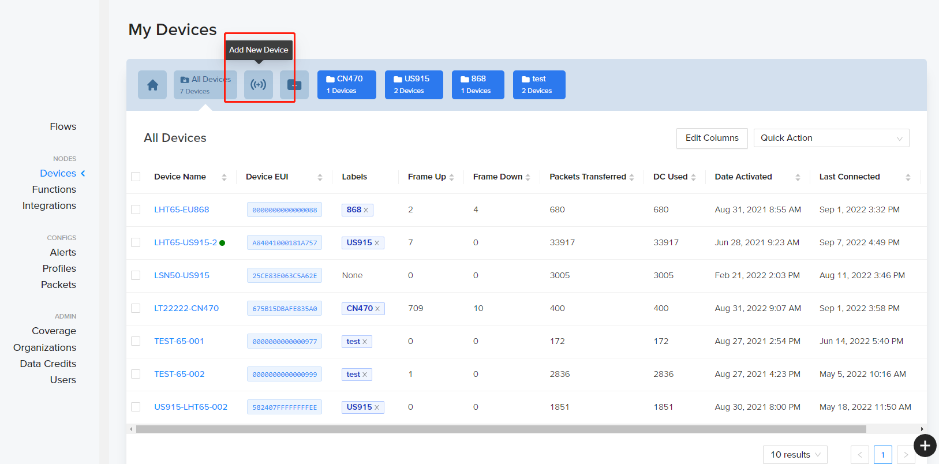
1.6 Example: How to join helium
1. Create a new device.
2. Save the device after filling in the necessary information.
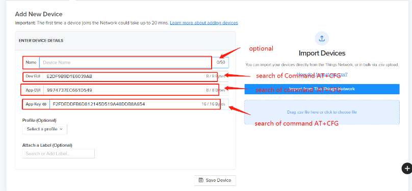
3. Use AT commands.
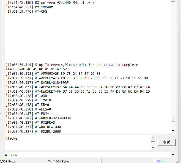
4. Use the serial port tool
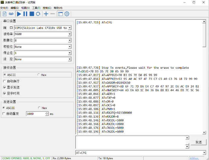
5. Use command AT+CFG to get device configuration
6. Network successfully.
7. Send uplink using command

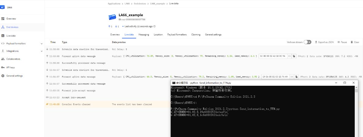
1.7 Example: Send PC's CPU/RAM usage to TTN via python
Use python as an example:https://github.com/dragino/LA66/blob/main/Send_information_to_TTN_WindosPC.py
(Raspberry Pi example: https://github.com/dragino/LA66/blob/main/Send_information_to_TTN_Raspberry%20Pi.py)
Preconditions:
1. LA66 USB LoRaWAN Adapter works fine
2. LA66 USB LoRaWAN Adapter is registered with TTN
Steps for usage:
1. Press the reset switch RESET on the LA66 USB LoRaWAN Adapter
2. Add decoder on TTN
3. Run the python script in PC and see the TTN
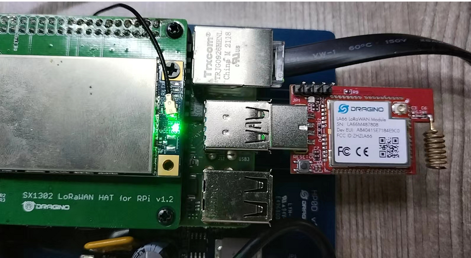
1.8 Example: Send & Get Messages via LoRaWAN in RPi
Assume user already input the LA66 USB LoRaWAN Adapter OTAA Keys in TTN and there is already TTN network coverage.
1. Connect the LA66 USB LoRaWAN Adapter to the Raspberry Pi
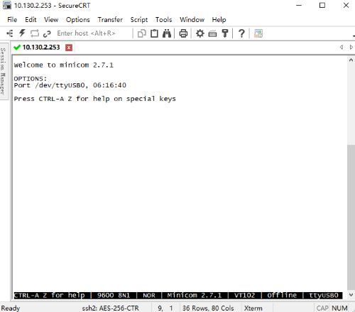
2. Install Minicom in RPi.
Enter the following command in the RPi terminal
apt update
apt install minicom
Use minicom to connect to the RPI's terminal
3. Press the reset switch RST on the LA66 USB LoRaWAN Adapter.
The following picture appears to prove that the LA66 USB LoRaWAN Adapter successfully entered the network.
4. Send Uplink message
Format: AT+SENDB=<confirn_status>,<Fport>,<data_len>,<data>
example: AT+SENDB=01,02,8,05820802581ea0a5
Check to see if TTN received the message
1.9 Example: Use of LA66 USB LoRaWAN Adapter and mobile APP
1.9.1 Hardware and Software Connection
Overview:
DRAGINO-LA66-APP is an Open Source mobile APP for LA66 USB LoRaWAN Adapter. DRAGINO-LA66-APP has below features:
- Send real-time location information of mobile phone to LoRaWAN network.
- Check LoRaWAN network signal strengh.
- Manually send messages to LoRaWAN network.
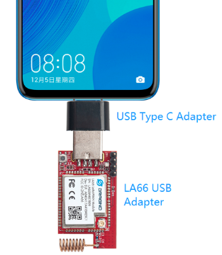
Hardware Connection:
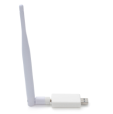
A USB to Type-C adapter is needed to connect to a Mobile phone.
Note: The package of LA66 USB adapter already includes this USB Type-C adapter.
Download and Install App:
Download Link for Android apk . (Android Version Only)

Use of APP:
Function and page introduction:
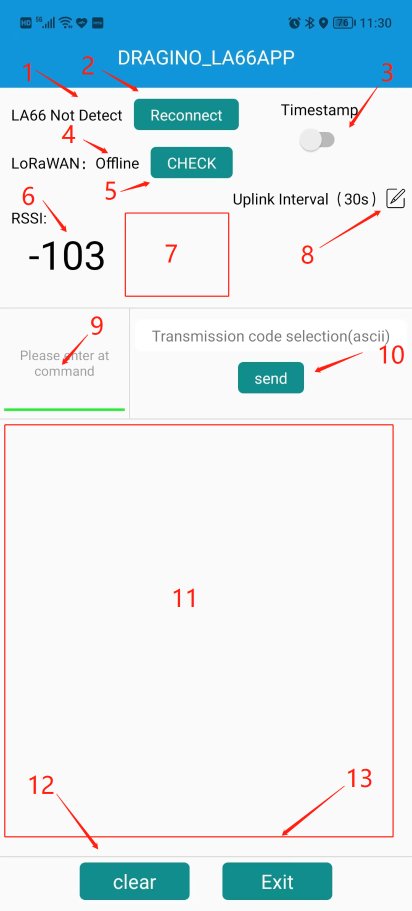
Block Explain:
1. Display LA66 USB LoRaWAN Module connection status
2. Check and reconnect
3. Turn send timestamps on or off
4. Display LoRaWan connection status
5. Check LoRaWan connection status
6. The RSSI value of the node when the ACK is received
7. Node's Signal Strength Icon
8. Configure Location Uplink Interval
9. AT command input box
10. Send Button: Send input box info to LA66 USB Adapter
11. Output Log from LA66 USB adapter
12. clear log button
13. exit button
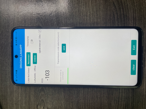
LA66 USB LoRaWAN Module not connected:
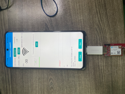
Connect LA66 USB LoRaWAN Module:
1.9.2 Send data to TTNv3 and plot location info in Node-Red
1. Register LA66 USB LoRaWAN Module to TTNV3
2. Open Node-RED,And import the JSON file to generate the flow
Sample JSON file please go to this link to download.
For the usage of Node-RED, please refer to: http://wiki.dragino.com/xwiki/bin/view/Main/Node-RED/
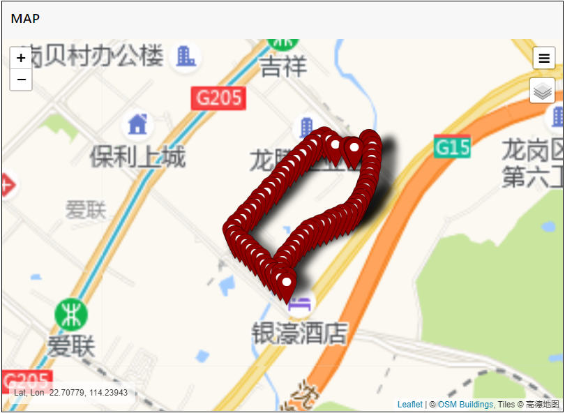
After see LoRaWAN Online, walk around and the APP will keep sending location info to LoRaWAN server and then to the Node Red.
LA66--node-red--decoder:dragino-end-node-decoder/Node-RED at main · dragino/dragino-end-node-decoder · GitHub
Example output in NodeRed is as below:
1.10 Upgrade Firmware of LA66 USB LoRaWAN Adapter
1.10.1 LA66V1 Update method
The LA66 USB LoRaWAN Adapter is the same as the LA66 LoRaWAN Shield update method.
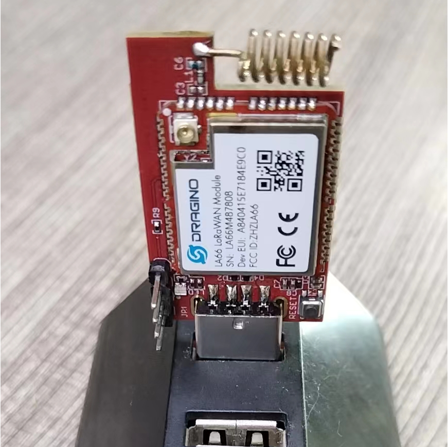
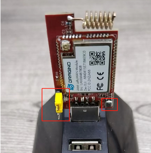
Just use the yellow jumper cap to short the BOOT corner and the RX corner, and then press the RESET button (without the jumper cap, you can directly short the BOOT corner and the RX corner with a wire to achieve the same effect).
Firmware download:
Notice: If upgrade via USB hub is not sucessful. try to connect to PC directly.
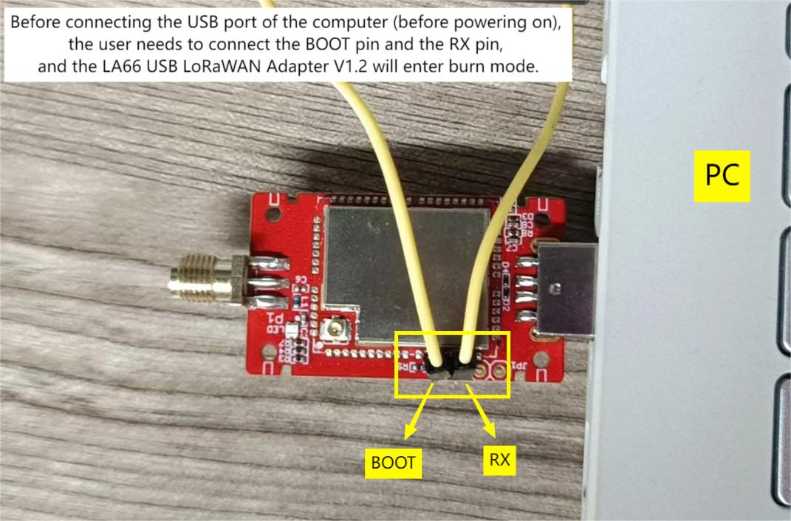
For the LA66 USB LoRaWAN Adapter v1.2, the hardware design has eliminated the reset button, so the first step we need to use the DuPont wire to connect the BOOT pin to the RX pin. Second, connect the LA66 USB LoRaWAN Adapter v1.2 to a USB hub or computer USB port so that it will enter burn mode. Then follow the steps below to burn the firmware.
Note: After the successful burning need to unplug the LA66 USB LoRaWAN Adapter v1.2, and then reconnect the computer interface, so that it will exit the burning mode.
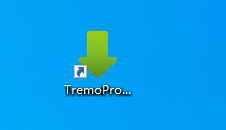
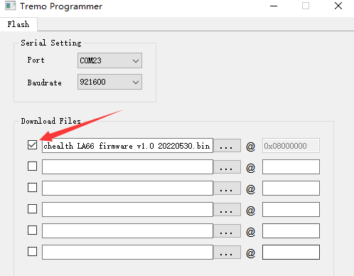
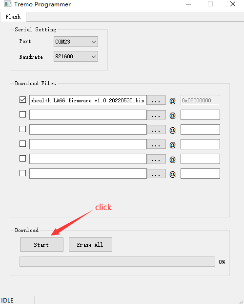
Open the Upgrade tool (Tremo Programmer) in PC and Upgrade
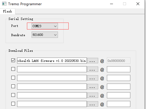
1. Software download link: https://www.dropbox.com/sh/j0qyc7a9ejit7jk/AACtx2tK4gEv6YFXMIVUM4dLa?dl=0
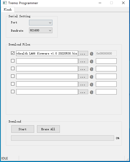
2. Select the COM port corresponding to USB TTL
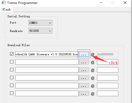
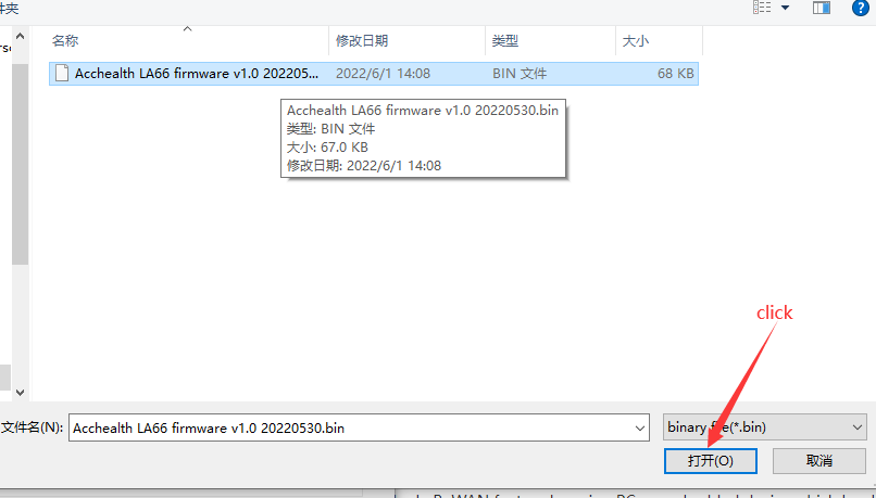
3. Select the bin file to burn
4. Click to start the download
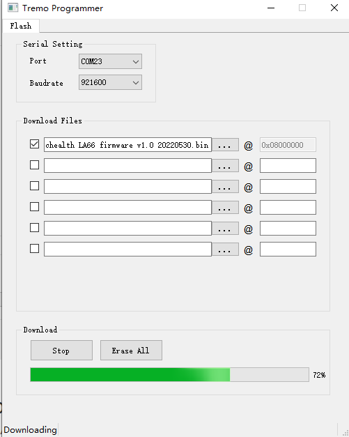
5. Check update process
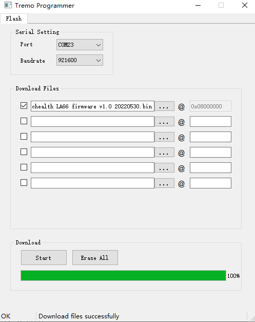
The following picture shows that the burning is successful
1.10.2 LA66V2 Update method
Firmware download(Please select withbootloader version):
Firmware update method:
Please refer to this link
2. FAQ
2.1 How to Compile Source Code for LA66?
Compile and Upload Code to ASR6601 Platform :Instruction
2.2 Where to find Peer-to-Peer firmware of LA66?
Instruction for LA66 Peer to Peer firmware : Instruction
2.3 My device keeps showing invalid credentials, the device goes into low power mode
Set the AT+COMMAND: AT+UUID=666666666666
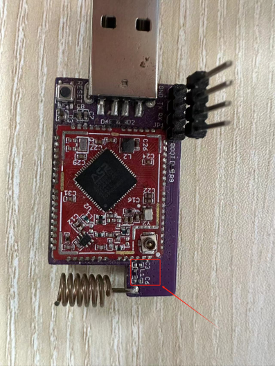
2.4 How to use external antenna via ipex connector?
You need to remove the spring antenna first, and also remove the resistor and capacitor.
Connect external antenna.
3. Order Info
Part Number: LA66-USB-LoRaWAN-Adapter-XXX
XXX: The default frequency band
- AS923: LoRaWAN AS923 band
- AU915: LoRaWAN AU915 band
- EU433: LoRaWAN EU433 band
- EU868: LoRaWAN EU868 band
- KR920: LoRaWAN KR920 band
- US915: LoRaWAN US915 band
- IN865: LoRaWAN IN865 band
- CN470: LoRaWAN CN470 band
- PP: Peer to Peer LoRa Protocol
4. Reference
5. FCC Statement
FCC Caution:
Any Changes or modifications not expressly approved by the party responsible for compliance could void the user's authority to operate the equipment.
This device complies with part 15 of the FCC Rules. Operation is subject to the following two conditions: (1) This device may not cause harmful interference, and (2) this device must accept any interference received, including interference that may cause undesired operation.
IMPORTANT NOTE:
Note: This equipment has been tested and found to comply with the limits for a Class B digital device, pursuant to part 15 of the FCC Rules. These limits are designed to provide reasonable protection against harmful interference in a residential installation. This equipment generates, uses and can radiate radio frequency energy and, if not installed and used in accordance with the instructions, may cause harmful interference to radio communications. However, there is no guarantee that interference will not occur in a particular installation. If this equipment does cause harmful interference to radio or television reception, which can be determined by turning the equipment off and on, the user is encouraged to try to correct the interference by one or more of the following measures:
—Reorient or relocate the receiving antenna.
—Increase the separation between the equipment and receiver.
—Connect the equipment into an outlet on a circuit different from that to which the receiver is connected.
—Consult the dealer or an experienced radio/TV technician for help.
FCC Radiation Exposure Statement:
This equipment complies with FCC radiation exposure limits set forth for an uncontrolled environment.This equipment should be installed and operated with minimum distance 20cm between the radiator& your body.