MS48-LR -- LoRaWAN To Modbus Gateway
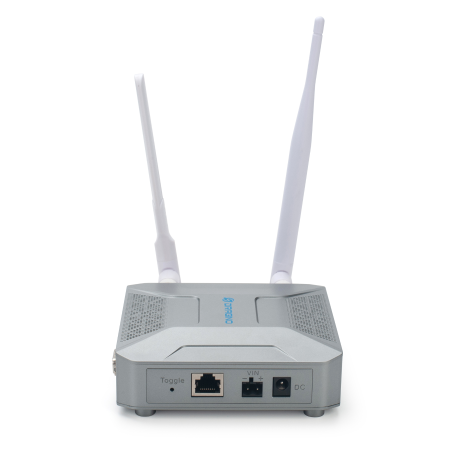
Table of Contents:
- 1. Introduction
- 2. Quick Start
- 2.1 Access and Configure MS48-LR
- 2.2 Typical Network Setup
- 2.3 Bridge LoRaWAN network to Modbus network
- Step 1: Configure the LoRa Radio to your area Frequency Plan
- Step 2: Copy the unique Gateway EUI & Configure the LoRaWAN Server address
- Step 3: Enable the Built-in LoRaWAN Network Server
- Step 4: Logging to the Built-in LoRaWAN Network Server
- Step 5: Register the gateway to the built-in ChirpStack
- Step 6: Register the Sensor-node to the built-in ChirpStack
- Step 7: Configure Modbus RTU/TCP Slave
- Step 8: Configure Sensor decode to Built-in Chirpstack
- Step 9: Configure Modbus RTU/TCP Slave Sensor Decode
- 2.4 Accept data to registers for specified Fport
- 2.5 Modbus Downlink
- 3. Web Configure Pages
- 4. Build-in Server
- 5. Use RS232 Interface
- 6. Use RS485 Interface
- 7. Power Analyze
- 8. More Services
- 9. Trouble Shooting
- 10. Supports
- 11. Order Info
- 12. Manufacturer Info
- 13. FCC Warning
1. Introduction
1.1 What is MS48-LR
The MS48-LR is an open-source LoRaWAN gateway that can convert LoRaWAN to Modbus RTU/TCP. It lets you bridge LoRa wireless network to an IP network via WiFi , Ethernet or Cellular Network (via Optional 4G module). The LoRa wireless allows users to send data and reach extremely long ranges at low data rates.
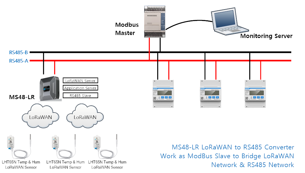
The MS48-LR is fully compatible with LoRaWAN protocol. MS48-LR includes a built-in LoRaWAN Server and IoT server, User can connect virous LoRaWAN devices to MS48-LR, and use PLC to access these devices via Modbus network, MS48-LR eliminates the need to add additional lorawan gateways to implement LoRaWAN to Modbus RTU/TCP.
Different countries use different LoRaWAN frequency bands. MS48-LR has these bands pre-configured. Users can also customize the frequency bands to use in their own LoRa network.
MS48-LR supports remote management. System Integrator can easy to remote monitor the gateway and maintain it.
1.2 How does it work?
The MS48-LR can run as a Modbus RS485-RTU slave, which converts the LoRaWAN sensor upstream data into modbus data and writes it into the register of the 03 function code
1.3 Specifications
Hardware System:
- CPU: Quad-core Cortex-A7 1.2Ghz
- RAM: 512MB
- eMMC: 4GB
Interface:
- 10M/100M RJ45 Ports x 1
- Multi-Channel LoRaWAN Wireless
- WiFi 802.11 b/g/n
- USB 2.0 host connector x 1
- Mini-PCI E connector x 1
- RS485 Interface x 1
- RS232 Interface x 1
LoRa Spec:
- Up to -140 dBm sensitivity with SX1250 Tx/Rx front-end
- 70 dB CW interferer rejection at 1 MHz offset
- Able to operate with negative SNR, CCR up to 9dB
- 8 x 8 channels LoRa packet detectors,8 x SF5-SF12 LoRa demodulators,8 x SF5-SF10 LoRa demodulators,125/250/500 kHz LoRa demodulator and 1 x (G)FSK demodulator
- Dual digital TX & RX radio front-end interfaces
- 10 programmable parallel demodulation paths
- Dynamic data-rate (DDR) adaptation
- True antenna diversity or simultaneous dual-band operation
Cellular 4G LTE (optional):
- Quectel: EC25 LTE module
- Standard Size SIM Slot
- 2 x 4G Sticker Antenna.
- Up to 150Mbps downlink and 50Mbps uplink data rates
- Worldwide LTE,UMTS/HSPA+ and GSM/GPRS/EDGE coverage
- MIMO technology meets demands for data rate and link reliability in modem wireless communication systems
Operating Condition:
- Work Temperature: -20 ~ 70°C
- Storage Temperature: -20 ~ 70°C
- Power Input: 12V, 2A, DC
1.4 Features
- Open Source Debian system
- Managed by Web GUI, SSH via WAN or WiFi
- Remote Management
- Auto-provisioning for batch deployment and management
- LoRaWAN Gateway
- 10 programmable parallel demodulation paths
- Pre-configured to support different LoRaWAN regional settings.
- Allow customizing LoRaWAN regional parameters.
- Different kinds of LoRaWAN Connections such as
- Semtech UDP Packet Forwarder
- LoRaWAN Basic Station
- ChirpStack-Gateway-Bridge (MQTT)
- Built-in ChirpStack local LoRaWAN server
- Built-in Node-Red local Application server
- Act as Modbus Slave mode
1.5 LED Indicators
MS48-LR has totally four LEDs, They are:
➢ LED 1 (ETH LED): This GREEN LED will blink GREEN when the ETH port is connecting
➢ LED 2 (RET LED): This GREEN LED will show different colors in different states:
✓ SOLID GREEN: When the Long press 4-5s Toggle button,the device will reload the Network and Initialize wifi configuration,This GREEN LED will SOLID GREEN Until the reload is finished.
✓ BLINKING GREEN: When the Long press 10s Toggle button,the device will restore the factory settings,This GREEN LED will BLINKIND GREEN Until the restore is finished.
➢ LED 3: This GREEN LED is undefined
➢ LED 4 (Power LED): This GREEN LED will be solid if the device is properly powered
➢ LED 5 (WIFI LED): This LED shows the WIFI interface connection status.
✓ SOLID GREEN: The device enables the WiFi WAN Client and connects to the WiFi successfully.
✓ BLINKING GREEN: The device's WiFi WAN Client connection is unsuccessful.
✓ OFF: The device WiFi WAN Client is not enabled.
➢ LED 6 (SYS LED): This GREEN LED will show different colors in different states:
✓ SOLID GREEN: The device is alive with a LoRaWAN server connection.
✓ BLINKING GREEN: a) no LoRaWAN Connection. or b) Device is in booting stage, in this stage, it will BLINKING GREEN for several seconds and then with BLINKING GREEN together
✓ OFF: Device doesn't have an Internet connection.
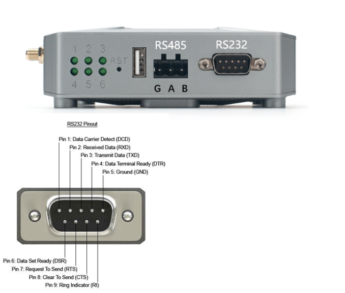
1.6 RS485 & RS232 interface
1.7 Button Instruction
The MS48-LR has two black buttons, which are:
RST: Press and release, and the gateway will restart
LED status: All LEDs are off except for the LED 4 (Power LED).
Toggle:
➢ Long press 4-5s : the gateway will reload the Network and Initialize wifi configuration
LED status: LED 2 (RET LED) will SOLID GREEN Until the reload is finished.
➢ Long press more than 10s: the gateway will restore the factory settings.
LED status: LED 2 (RET LED) will BLINKIND GREEN Until the restore is finished.
1.8 Installation

2. Quick Start
The MS48-LR supports network access via Ethernet or Wi-Fi connection and runs without a network.
In most cases, the first thing you need to do is make the MS48-LR accessible to the network.
2.1 Access and Configure MS48-LR
2.1.1 Find IP address of MS48-LR
Method 1: Connect via MS48-LR WiFi
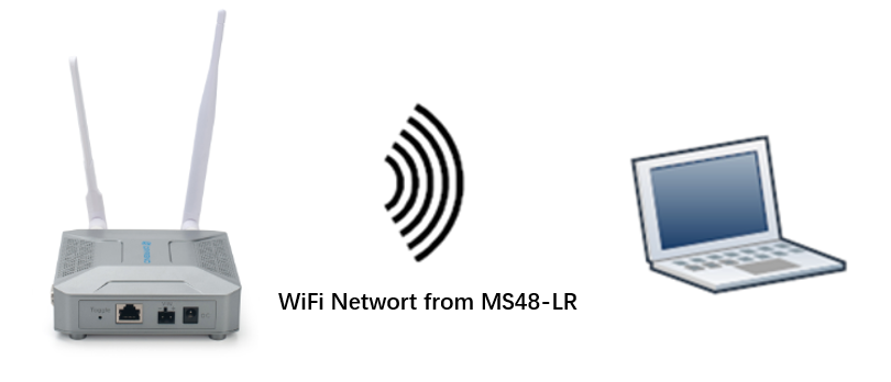
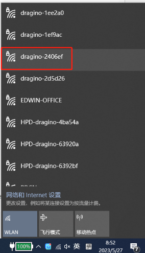
At the first boot of MS48-LR, it will auto generate a WiFi network called dragino-xxxxxx with password:
dragino+dragino
User can use a PC to connect to this WiFi network. The PC will get an IP address 10.130.1.xxx and the MS48-LR has the default IP 10.130.1.1
Method 2: Connect via Ethernet with DHCP IP from the router
Connect the MS48-LR Ethernet port to your router and MS48-LR can obtain an IP address from your router. In the router's management portal, you should be able to find what IP address the router has assigned to the MS48-LR.
You can also use this IP to connect.

Method 3: Connect via MS48-LR Fallback IP
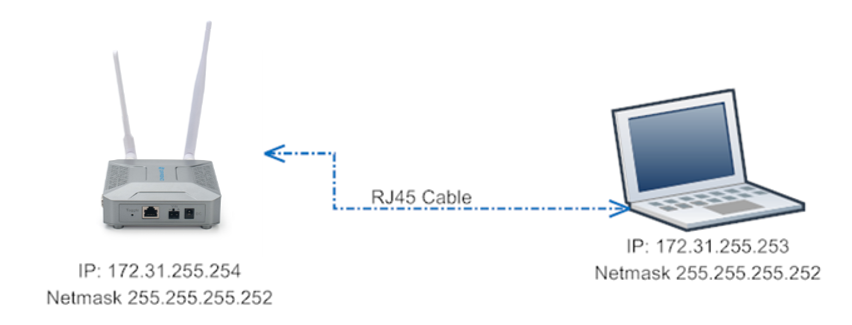
Steps to connect via fallback IP:
1. Connect the PC's Ethernet port to MS48-LR's WAN port
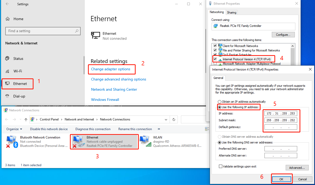
2. Configure PC's Ethernet port has IP: 172.31.255.253 and Netmask: 255.255.255.252
Settings --> Network & Internet --> Ethernet --> Change advanced sharing options --> Double-click"Ethernet" --> Internet Protocol Version 4 (TCP/IPv4)
As in the below photo:
Configure computer Ethernet port steps video:
If you still can't access the MS48-LR fallback ip, follow this connection to debug : Trouble Shooting
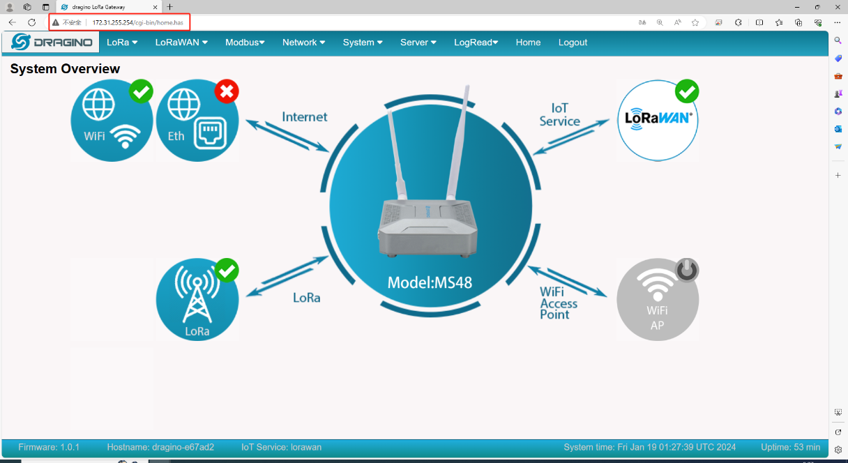
3. In the PC, use IP address 172.31.255.254 to access the MS48-LR via Web or Console.
Method 4: Connect via WiFi with DHCP IP from the router

Fill in the WiFi information by checking the box and clicking Save&Apply
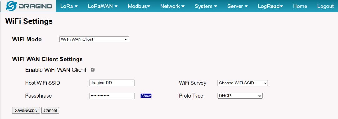
Wi-Fi configuration successful
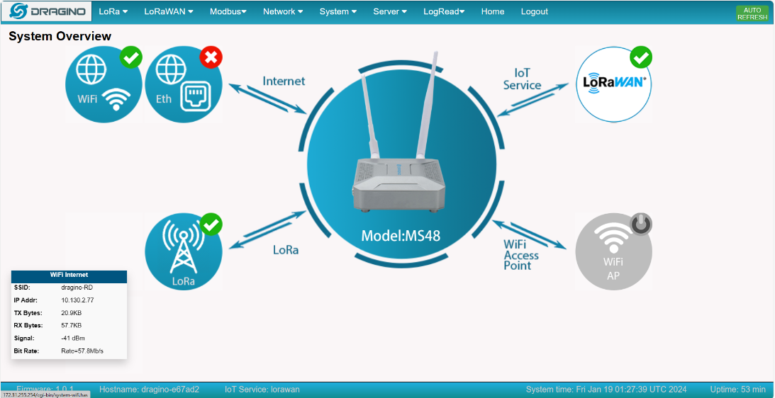
2.1.2 Access Configure Web UI
Web Interface
Open a browser on the PC and type the MS48-LR ip address (depends on your connect method)
http://IP_ADDRESS or http://172.31.255.254(Fallback IP)
You will see the login interface of MS48-LR as shown below.
The account details for Web Login are:
User Name: root
Password: dragino

2.2 Typical Network Setup
2.2.1 Overview
MS48-LR supports flexible network set up for different environment. This section describes the typical network topology can be set in MS48-LR. The typical network set up includes:
- WAN Port Internet Mode
- WiFi Client Mode
- Cellular Mode
2.2.2 Use the WAN port to access the Internet
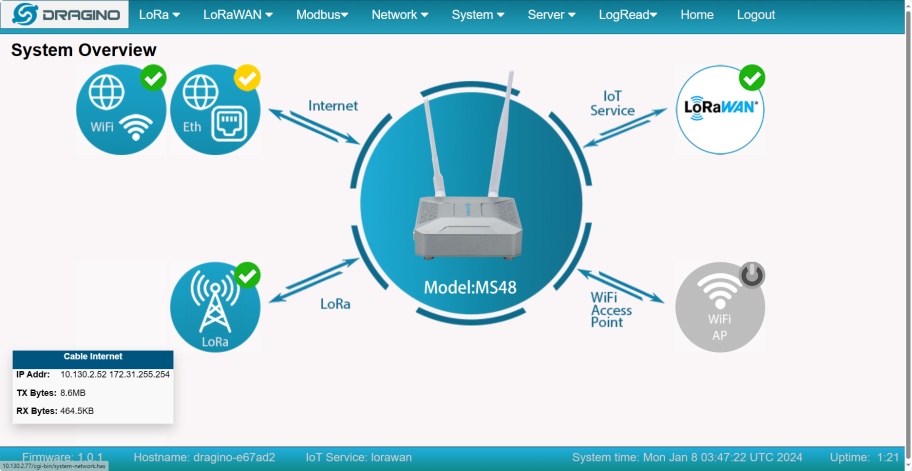
By default, the MS48-LR is set to use the WAN port to connect to an upstream network. When you connect the MS48-LR's WAN port to an upstream router, MS48-LR will get an IP address from the router and have Internet access via the upstream router. The network status can be checked on the home page:
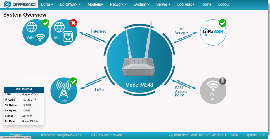
2.2.3 Access the Internet as a WiFi Client
In the WiFi Client Mode, MS48-LR acts as a WiFi client and gets DHCP from an upstream router via WiFi.
The settings for WiFi Client is under page Network --> Wi-Fi
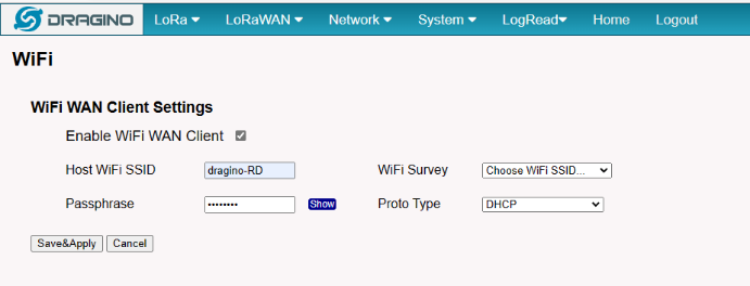
In the WiFi Survey Choose the WiFi AP, and input the Passphrase then click Save & Apply to connect.
2.2.4 Use built-in 4G modem for internet access
Users can see whether MS48-LR has EC25 on the label of the gateway to determine whether there is 3G/4G Cellular modem.
If the MS48-LR has 3G/4G Cellular modem, user can use it as main internet connection or back up.
First, install the Micro SIM card as below direction
Second, Power off/ ON MS48-LR to let it detect the SIM card.

The set up page is Network --> Cellular
While use the cellular as Backup WAN, device will use Cellular for internet connection while WAN port or WiFi is not valid and switch back to WAN port or WiFi after they recover.
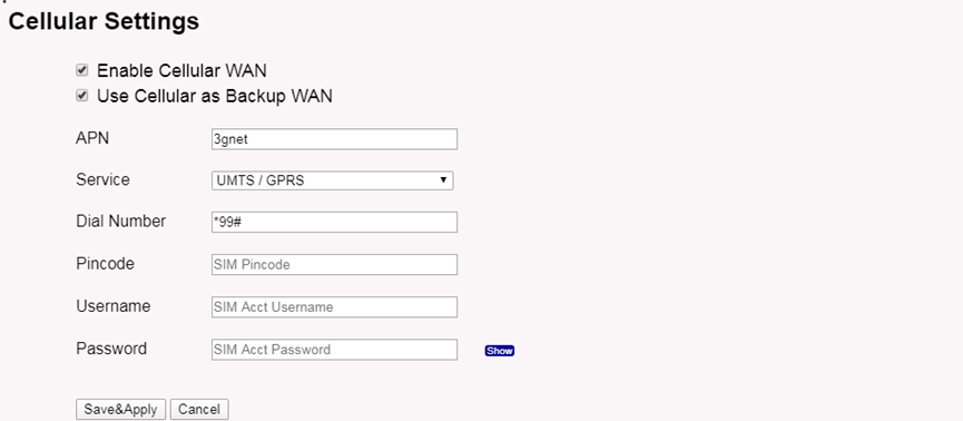
When cellular fails to connect or has problems, users can refer to this link to Trouble Shooting:How to Trouble Shooting if Cellular connection fails
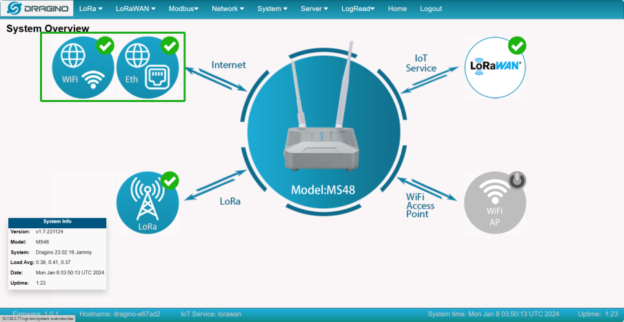
2.2.5 Check Internet connection
In the Home page, we can check the Internet connection.
- GREEN Tick
 : This interface has Internet connection.
 - Yellow Tick
 : This interface has IP address but don't use it for internet connection.
 - RED Cross
 : This interface doesn't connected or no internet.
2.3 Bridge LoRaWAN network to Modbus network
By following the steps below in the configuration example, Users can convert the uplink data of the lorawan sensor to modbus RTU/TCP data
MS48-LR eliminates the need to add additional lorawan gateways to implement LoRaWAN to Modbus RTU/TCP
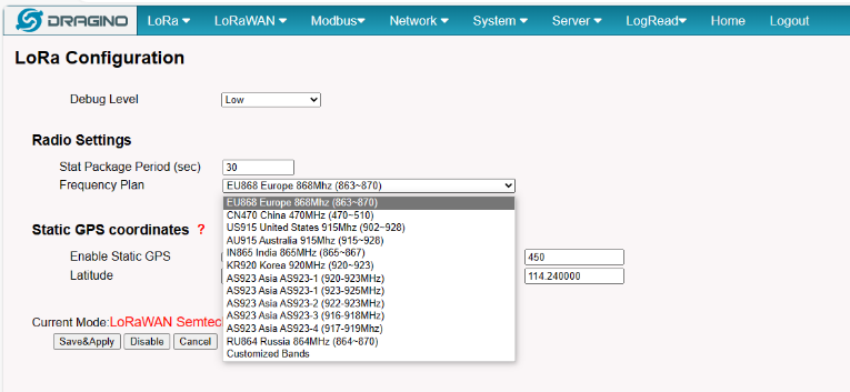
Step 1: Configure the LoRa Radio to your area Frequency Plan
The Frequency Plan has to be set the same as the Sensor node Frequency Plan.
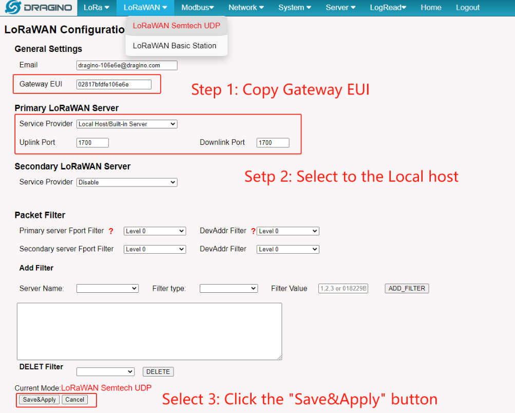
Step 2: Copy the unique Gateway EUI & Configure the LoRaWAN Server address
Users need to connect the MS48-LR configuration to the built-in lorawan server.
Every MS48-LR has a unique gateway EUI. The ID can be found on the LoRaWAN Semtech page:
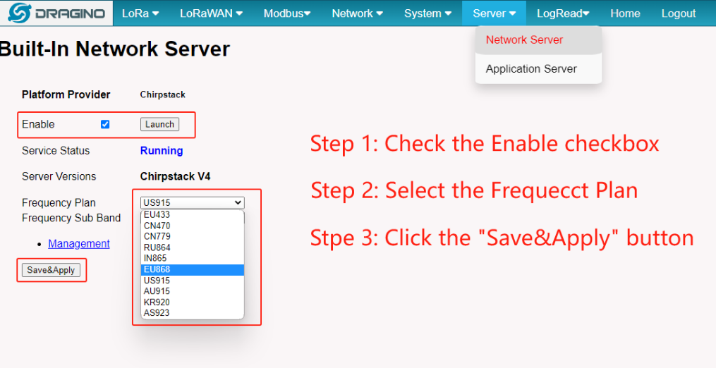
Step 3: Enable the Built-in LoRaWAN Network Server
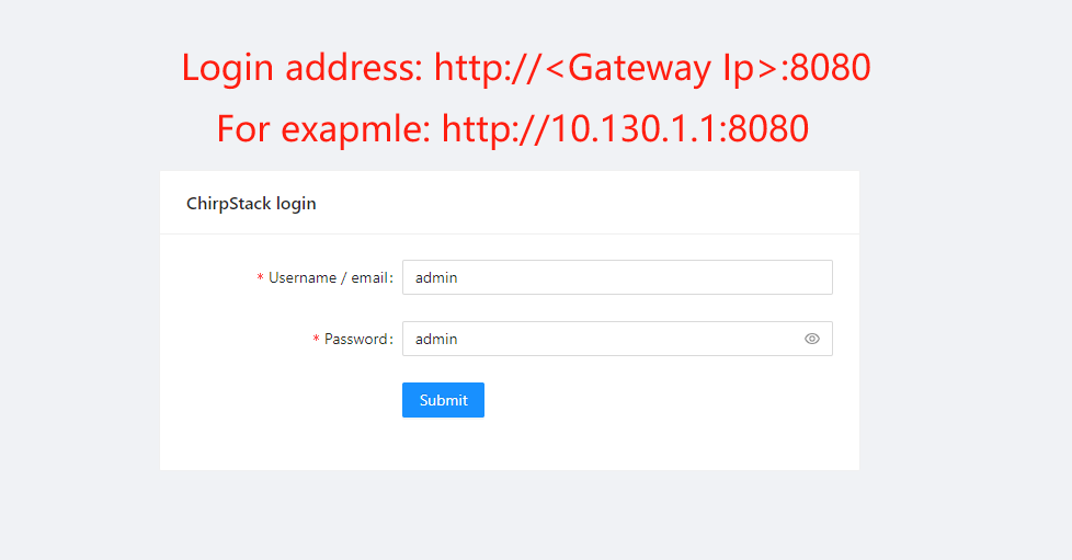
Step 4: Logging to the Built-in LoRaWAN Network Server
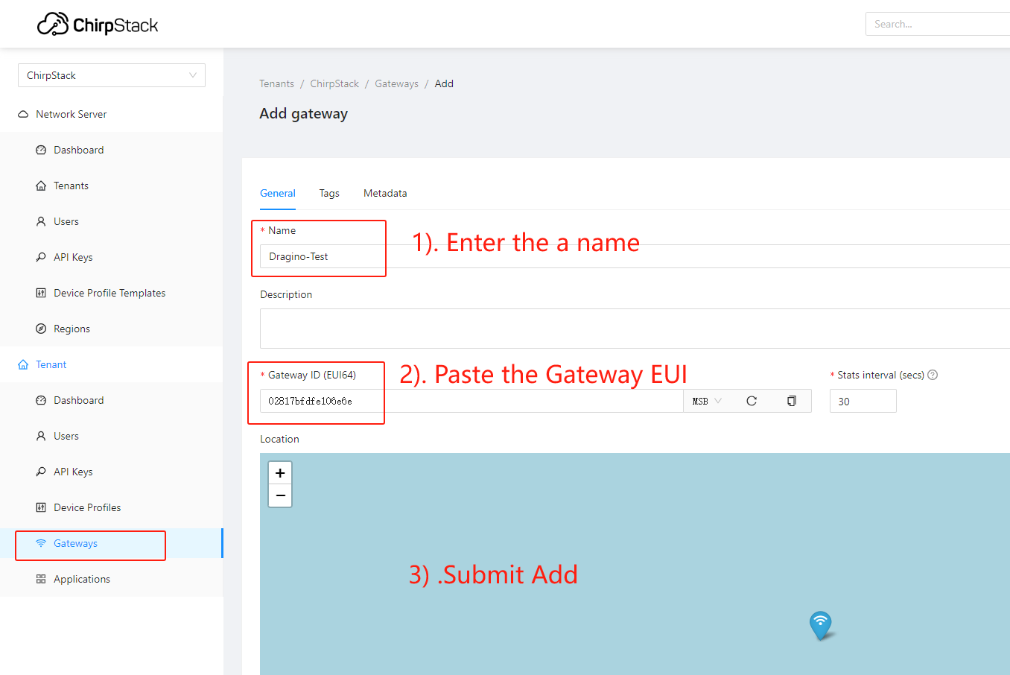
Step 5: Register the gateway to the built-in ChirpStack
Copy Gateway EUI from the previous step to the following interface:
Step 6: Register the Sensor-node to the built-in ChirpStack
The MS48-LR gateway is already set up to connect to the built-in ChirpStack network, so we now need to configure the sensor device to connect to the built-in ChirpStack.
First we need to add the Device Profiles and Application (ignore them if they are already done).
1) Add Device Profiles
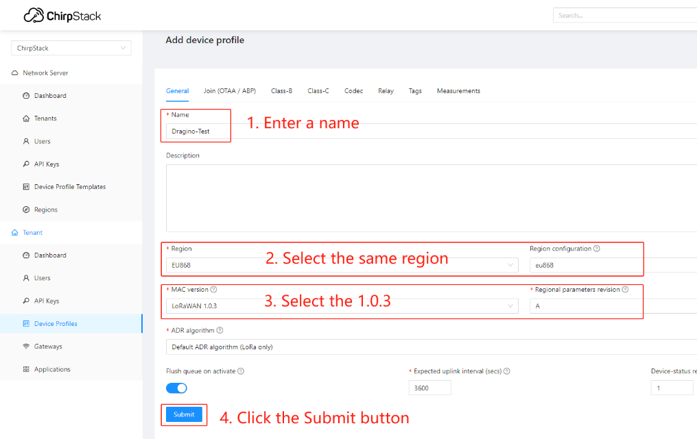
2) Add End Node Device
Create an Application
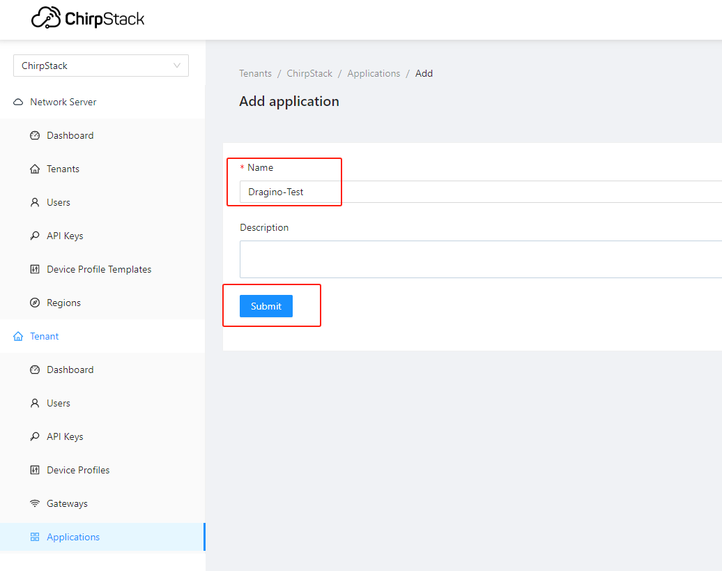
Add a device for the sensor node
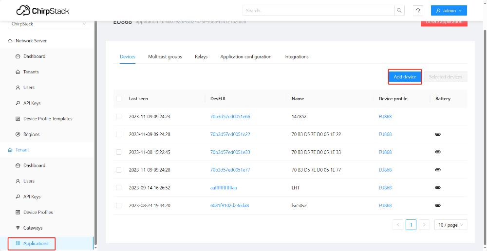
Enter Device EUI, Join EUI(APP EUI)and APPKEY of the node Device, and select the Device profile added in the previous step
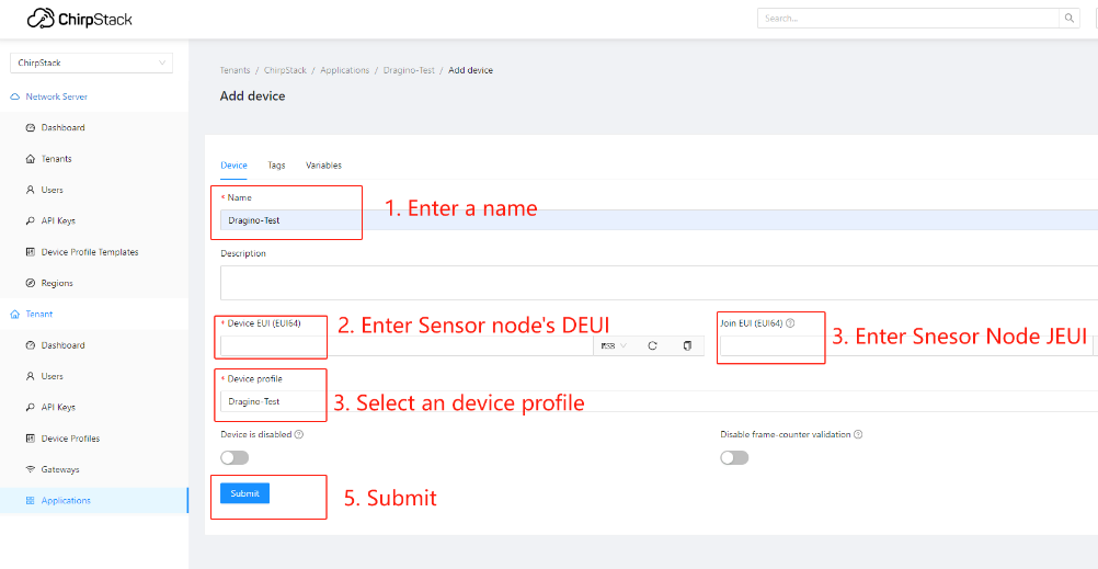
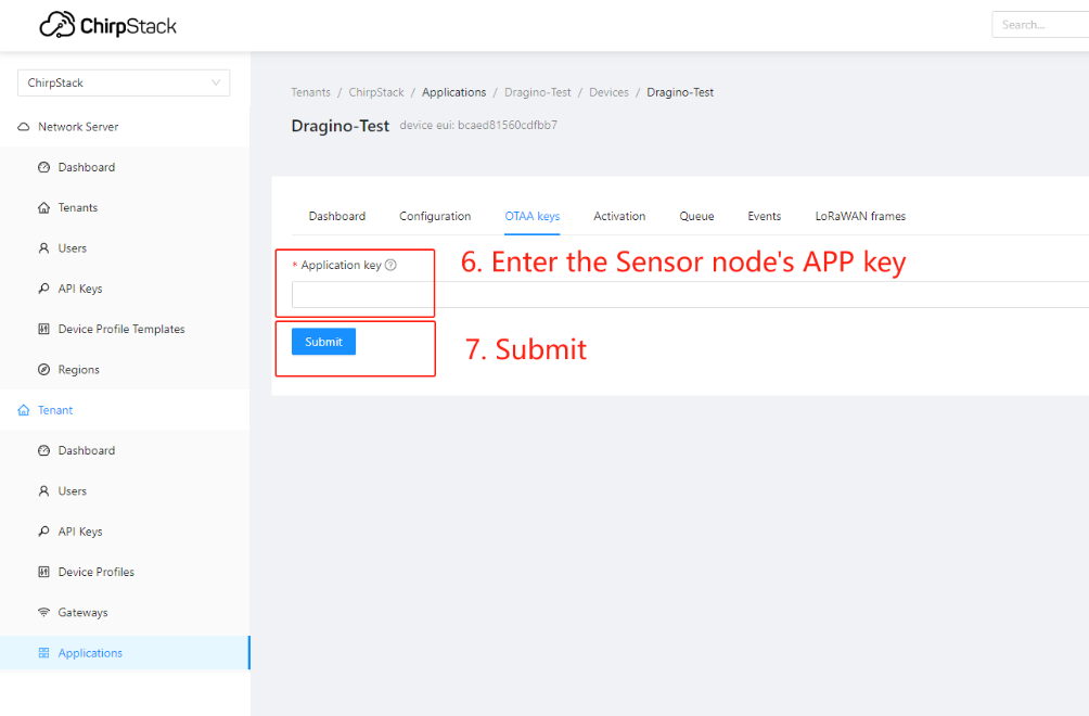
Step 7: Configure Modbus RTU/TCP Slave
The gateway can as a Modbus RTU slave to run, the user can set a range of the register to write a sensor node uplink data.
For example, there is a sensor node EUI is 70b3d57ed0051e22, the register start is 0xABCD and the register length is 14, which means the uplink data will be written to the register starting at 0xABCD register and the maximum write length not to exceed 14 registers.
So the sensor node 70b3d57ed0051e22 uplink data will be written to the 0xABCD - 0xABE1 register.
Note: Since the length of the payload is the same for different sensor nodes if The length of the data is greater than the configuration length, the data will be replaced with FFFF.
Slave Setting:
Slave Mode ---> Support both RTU and TCP mode
Enable Modbus Slave ---> Enable Slave
Slave Address/Port ---> Set the slave address/port
Show Sensor History ---> See the sensor data log
Sensor Settings:
Device EUI ---> Sensor node's EUI
Register Start ---> Setting the start register address to write the sensor node's data
Register Length ---> The maximum write length with register
Note: Only 1 sensor can be written in the range set by the registers
About how long the register needs to be configured:
In most cases, the payload length of Dragino's sensor is 11 bytes, which corresponds to a register length of 6.
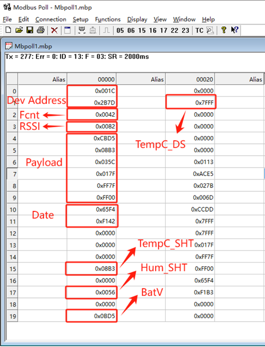
The modbus data forwarded by the gateway will have the Dev Address, Fcnt, Rssi, Payload, and Date of the sensor.
Dev Address occupies 2, Fcnt occupies 1, Rssi occupies 1, Date occupies 2, so by default you need to configure the register length to be greater than or for 12.
User can check the payload length on the Event page:

1) RTU Mode:
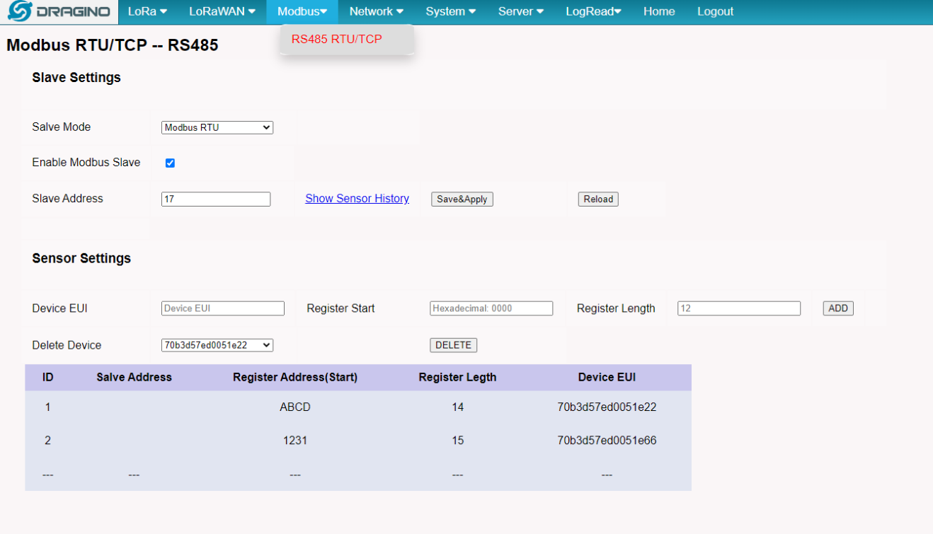
After the sensor node is active at the built-in server Chirpstack, the user can add it to this page and enable the Modbus RS485-RTU Slave.
Then MS48-LR will write the uplink data to the 03 code register and record the uplink data.
PLC read the MS48-LR register
Settings:
Function : 03 code
Bit rate : 9600
Parity bit : none
Stop bit : 1
Response Timeout : Greater than 3000ms
2) TCP Mode:
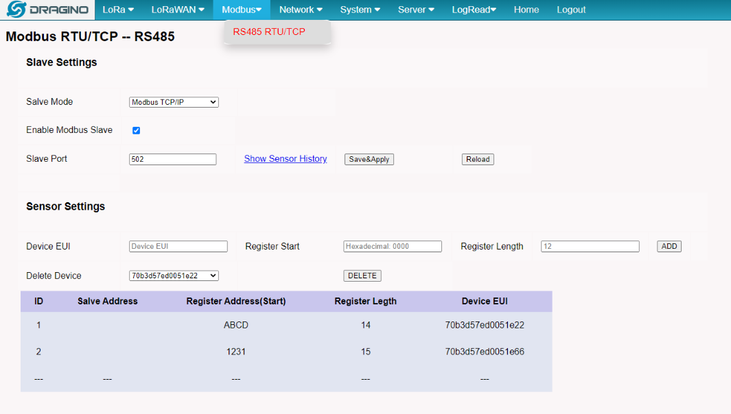
PLC read the MS48-LR register
Settings:
Function : 03 code
IP Address : Gateway IP Address
Server Port : Slave Port
Connect Timeout : Greater than 3000ms
3) PLC(Modbus server/master) data show:
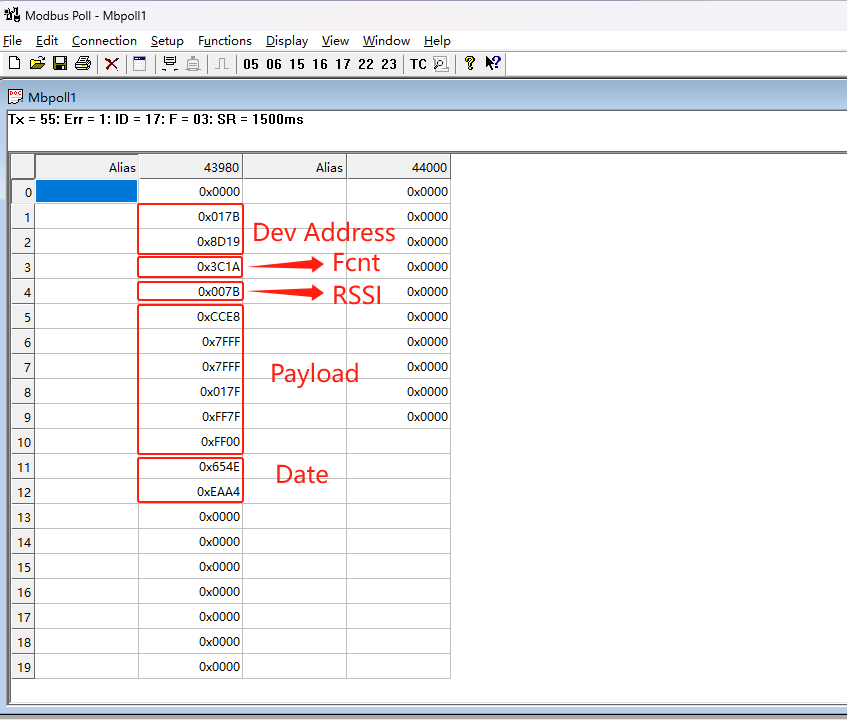
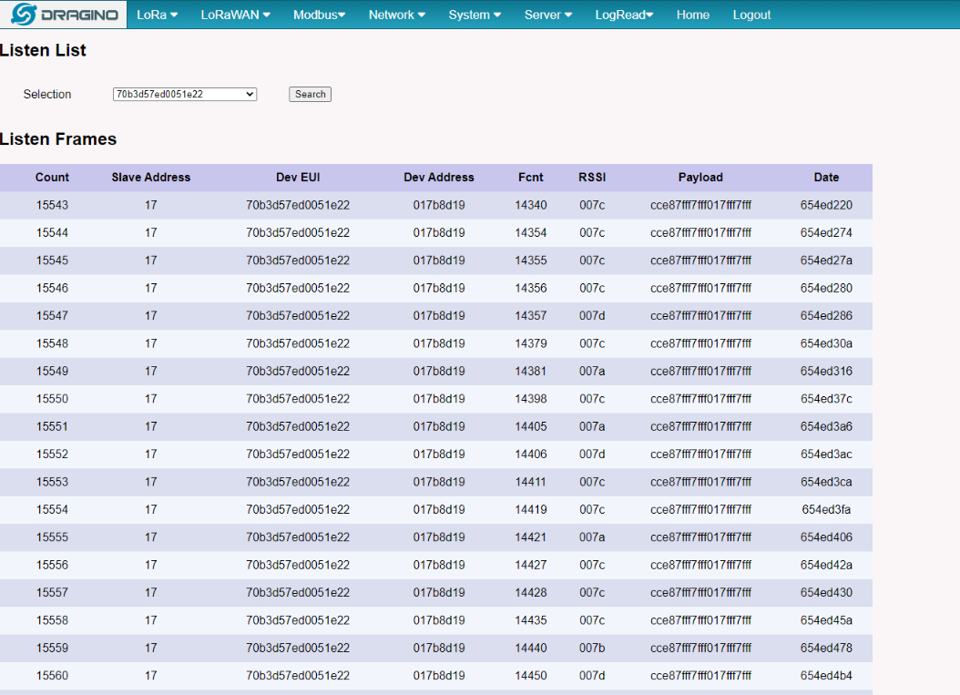
History Data:
Click the Show Sensor History will launch to this page
Step 8: Configure Sensor decode to Built-in Chirpstack
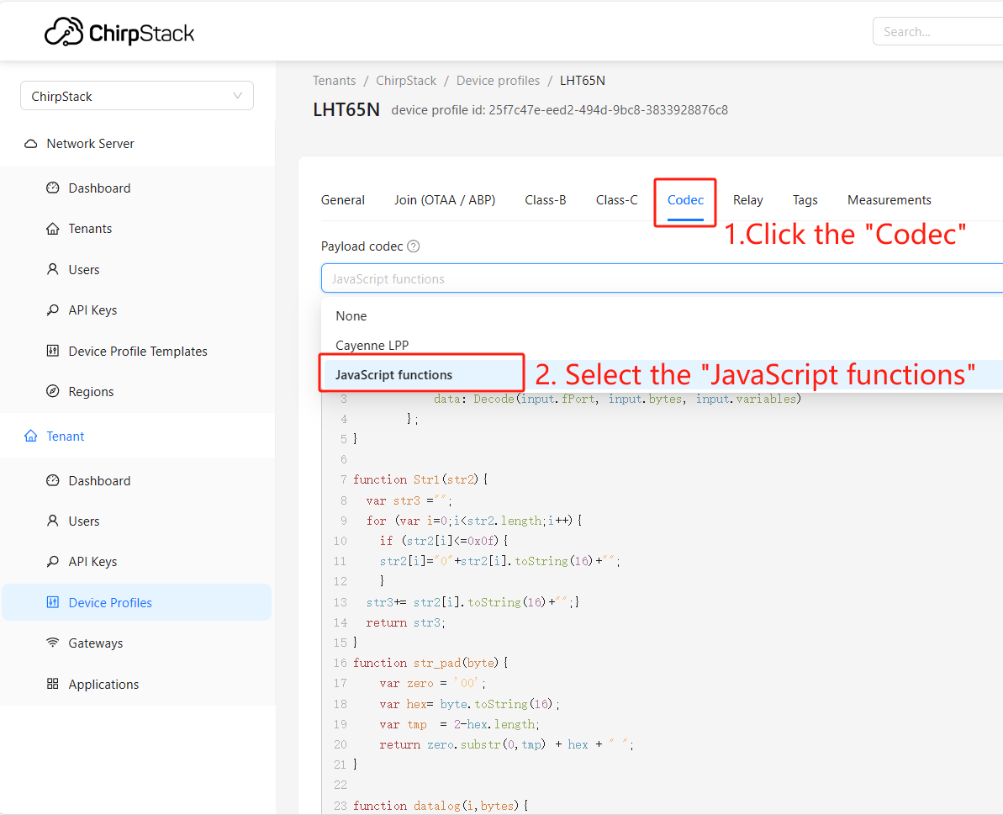
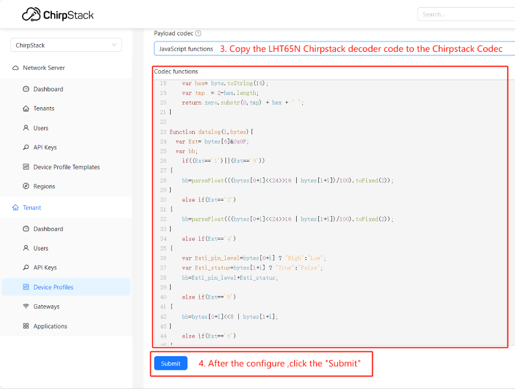
1) Add Sensor's decode to Chirpstack
Users can find the ChirpStack v4 decoder code for the Dragino End node in this link:
https://github.com/dragino/dragino-end-node-decoder
If the user's sensor is from another manufacturer, you need to search for the chirpstack decoder of the corresponding sensor on the official website of the corresponding manufacturer.
The following example is to add the LHT65N decoder:
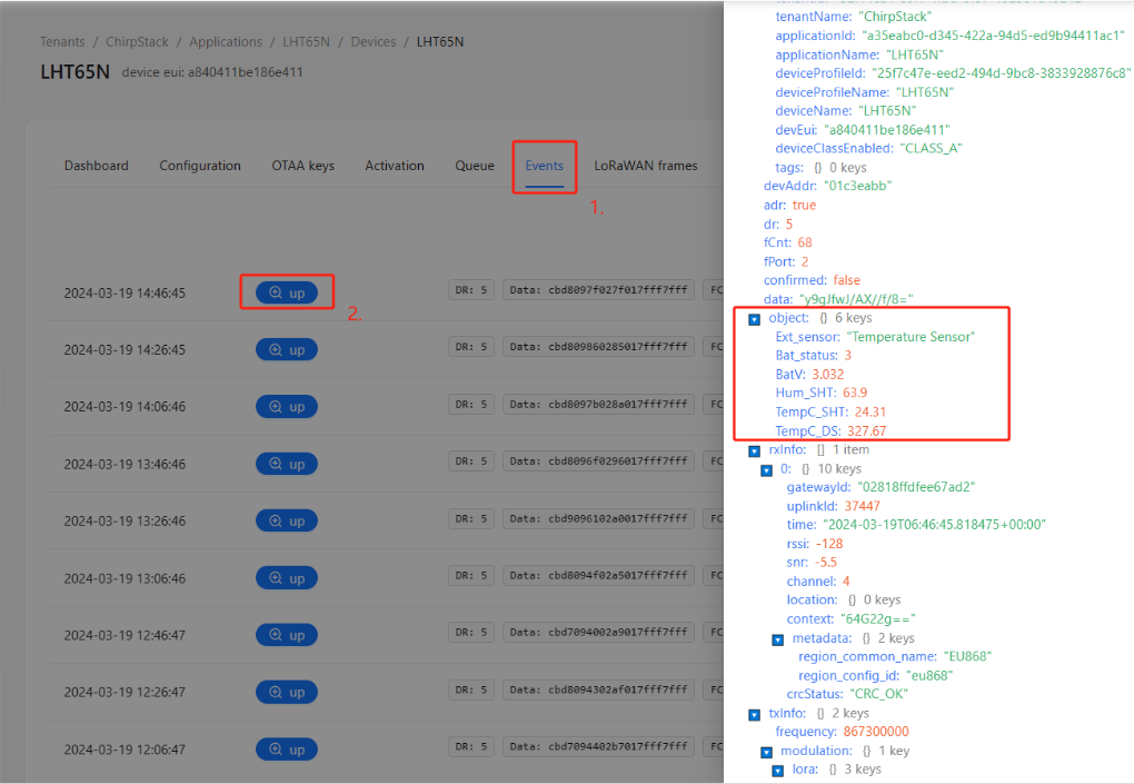
2) Check the decode on ChiprStack
Step 9: Configure Modbus RTU/TCP Slave Sensor Decode
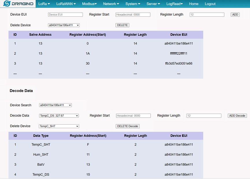
For example, there is a sensor node EUI is a840411be186e411, the register start is 0x0000 and the register length is 14, which means the uplink data will be written to the register starting at 0x0000 register and the maximum write length not to exceed 14 registers.
Add Decode Data TempC_SHT, the register start address is 0x000F and the register length is 2, which means the Decode Data TempC_SHT will be written to the register starting at 0x000F register and the maximum write length not to exceed 2 registers.
So the sensor node a840411be186e411 uplink data will be written to the 0x0000 - 0x000E register, and the Decode Data TempC_SHT will be written to the 0x000F - 0x0010 register.
Note: Since the length of the payload is the same for different sensor nodes if The length of the data is greater than the configuration length, the data will be replaced with FFFF.
Decode Data:
Device Type ---> Sensor decoder data
Register Start ---> Setting the start register address to write the sensor node's decoder data
Register Length ---> The maximum write length with register
Note: Only 1 Data can be written in the range set by the registers
PLC(Modbus server/master) data show:
Note: When the decoded data is a floating point number or a negative number, it will be encoded using IEEE754
For example: 23.20(real data) ---> 4037333333333333 [HEX](register show).
For example: -23.20(real data) --->C037333333333333 [HEX] (register show).
For example: 23(real data)-->4037000000000000 [HEX](register show).
2.4 Accept data to registers for specified Fport
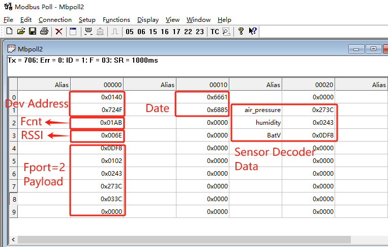
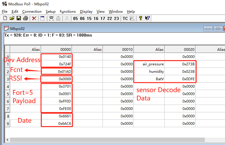
For example, there is a sensor node EUI is f4bbf5a0da6f4da5,
- the sensor payload uplink is using Fport=2
- the sensor status uplink is using Fport=5
If the accept fport is not set, it may cause the registers to be written with 0 decoded data during status uplink, because status uplinks typically do not contain decoded data.
To avoid 0 data being written to the registers. the users can set accept Fport for the sensor,
i.e., the data will be written to the register only when the MS48-LR receives the uplink of the specified Fort
Accept Fport:
DevEUI ---> Sensor node DevEUI
Accept FPort ---> Setting the Accept Fport

PLC(Modbus server/master) data show:
2.5 Modbus Downlink
The user can use Modbus downlink to send a payload to the sensor device
Prerequisites:
The preceding configurations are complete and the sensor data is forwarded properly
Step 1. Generate chirpstack API token
Users can generate API tokens on the API Keys interface with built-in chirpstack
Copy and save the API token after it is generated.

Step 2. Configuring API tokens and reloading the modbus service
Configure the API token from step 1 on the Downlink token and click "Reload"

Step 3. Configure downlink registers for the device
For example, there is a sensor node EUI is a84041a77259044c, the register start is 0x10 and the register length is 3, which means the downlink data will be written to the register starting at 0x10 register and the maximum write length not to exceed 3 registers.
So the sensor node a84041a77259044c downlink data will be written to the 0x10 - 0x13 register.
Downlink Settings:
Device EUI ---> Sensor node's EUI
Register Address(Start) ---> Setting the start register address to write the downlink data
Register Length ---> The maximum write length with register
Note: Only 1 sensor can be written in the range set by the registers

Step 4. Sent downlink to the MS48
For example, there is a sensor node EUI is a84041a77259044c, downlink is 2601
Note: that you need to use 16 function codes to write downlink data for the registers
It is required that the downlink registers do not hold data in existence, otherwise a large number of downlink will be generated

By default, each register occupies 16 bits (2 bytes). Therefore, when the client sends data such as 030101, it is necessary to directly add FFFFF in the single register, for example: 0x0301, 0xFFFF, 0xFF01,
the gateway will automatically convert it to 030101 downlink

Step 5. Check chirpstack Queue
After the downlink is sent, the user can check whether the downlink queue is generated on the Queue page of the sensor device on the built-in chirpstack

The above single-byte register downlink queue results

3. Web Configure Pages
3.1 Home
Shows the system running status:
3.2 LoRa Settings
3.2.1 LoRa --> LoRa
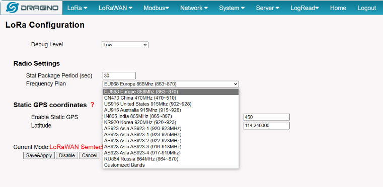
This page shows the LoRa Radio Settings. There is a set of default frequency bands according to LoRaWAN protocol, and users can customize the band* as well.
Different MS48-LR hardware versions can support different frequency ranges:
- 868: valid frequency: 863Mhz ~ 870Mhz. for bands EU868, RU864, IN865, or KZ865.
- 915: valid frequency: 902Mhz ~ 928Mhz. for bands US915, AU915, AS923 or KR920
After the user choose the frequency plan, the user can see the actual frequency is used by checking the page LogRead --> LoRa Log
Note *: See this instruction for how to customize the frequency band: How to customized LoRaWAN frequency band - DRAGINO
3.3 LoRaWAN Settings
3.3.1 LoRaWAN --> LoRaWAN Semtech UDP
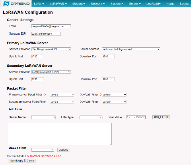
This page is for the connection set up to a general LoRaWAN Network server such as TTN, ChirpStack, etc.
3.3.2 LoRaWAN --> LoRaWAN Basic Station
This page is for the connection set up to the TTN Basic Station, AWS-IoT, etc.
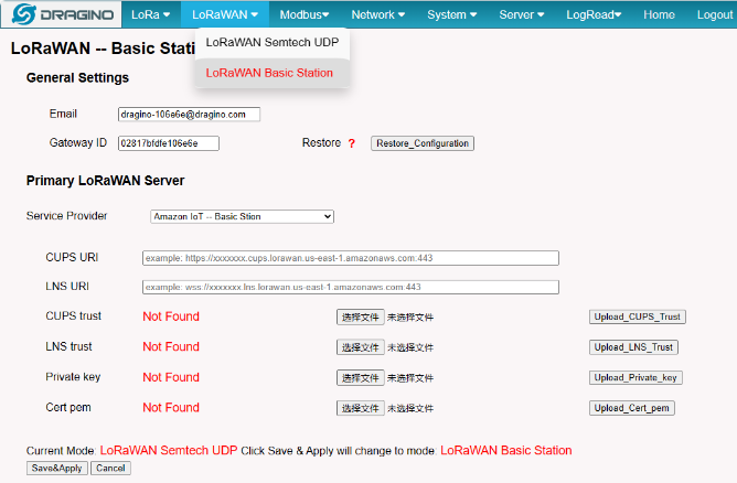
Please see this instruction to know more detail and a demo for how to use of LoRaWAN Basic Station: Use of LoRaWAN Basic Station - DRAGINO
3.4 Network Settings
3.4.1 Network --> WiFi
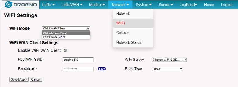
Users can configure the wifi WAN and enable Wifi Access Point on this interface
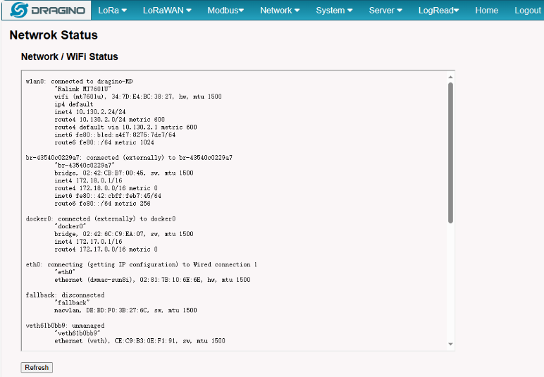
3.4.2 Network --> System Status
3.4.3 Network --> Network
In the Network --> Network interface, Users can set the Ethernet WAN static ip address.

3.4.4 Network --> Cellular
In the Network --> Cellular interface, Users can Enable Cellular WAN and configure Celluar.
Note: APN cannot be empty.
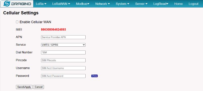
After the configuration is complete, return to the Home interface and put the mouse on the Cell icon to check the Cellular state.
When cellular fails to connect or has problems, users can refer to this link to Trouble Shooting:How to Trouble Shooting if Cellular connection fails
3.5 System
3.5.1 System --> System Overview
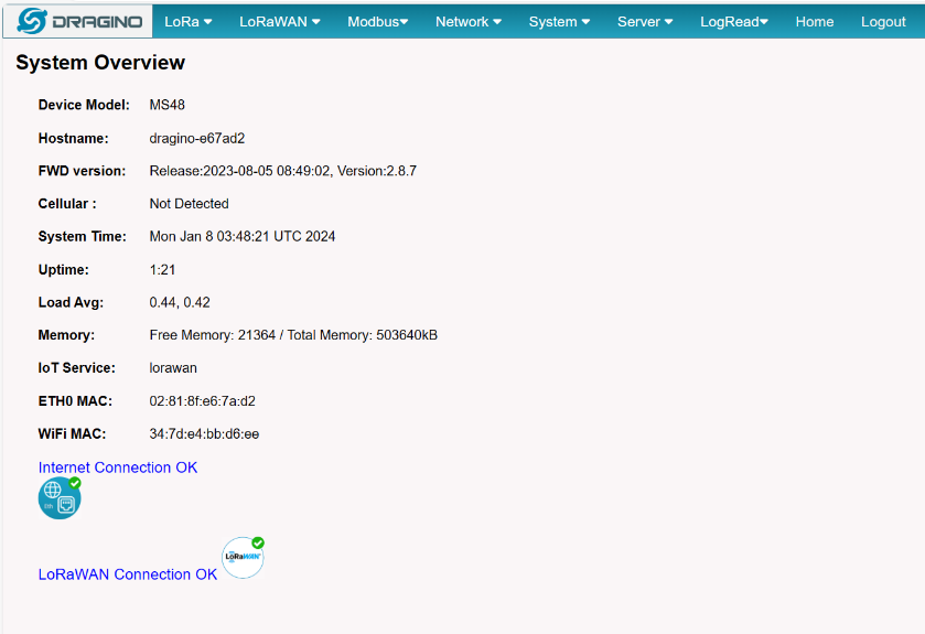
Shows the system info:
3.5.2 System --> System General
There are two login for MS48-LR: root /dragino or admin /dragino. Both root and admin has the same right for WEB access. But root user has also the right to access via SSH to Linux system. admin only able to access WEB interface.
This page can be used to set the password for them.
Timezone: Set device timezone.
Time Synchronization Service: Set the time synchronization server.
HTTP Web Service: Enable/Disable the HTTP service via WAN interface.
Terminal Service: Enable/Disable the SSH service via WAN interface.
Fallback Settings: Enable/Disable the Fallback interface.
Keepalive_Script: Set the keepalive_scrpt interval.

3.5.3 System --> Backup/Restore

3.5.4 System --> Remoteit
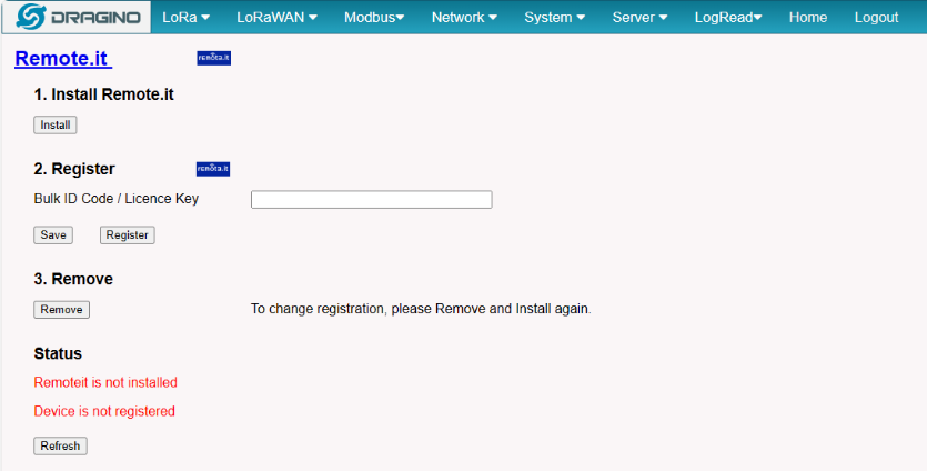
In the System-> Remoteit interface, users can configure the gateway to be accessed remotely via Remote.it.
the users can refer to this link to configure them: Monitor & Remote Access Gateway
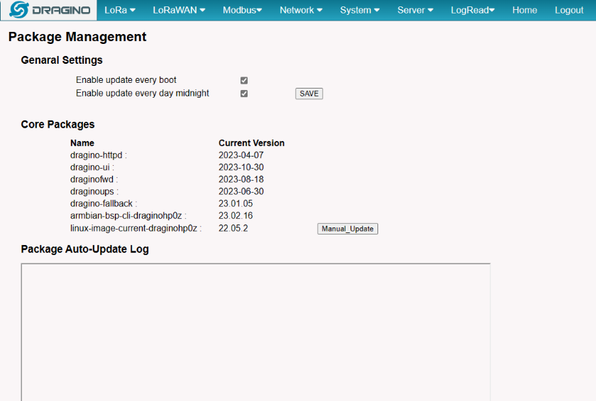
3.5.5 System --> Package Management
In the System --> Package Management interface, Users can check the current version of Core Packages.
4. Build-in Server
the default factory version of MS48-LR is installed with the built-in Applicant server: Node-Red, LoRaWAN Server: ChirpStack.
Note:
Path: Server --> Network Server
Server --> Application Server
Troubleshooting:
1. URL does not jump properly
For the ChirpStack, you can use the local IP address and the port is 8080 to access it.
For the Node-Red, you can use the local IP address and the port is 1880 to access it.
4.1 LoRaWAN Network Server -- ChirpStack
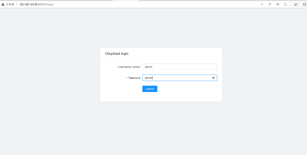
You can access the gateway's built-in LNS server of ChirpStack via the URL( http://<hostname>:8080 or http://<local-IPV4-address> ) in your browser.
Such as http://dragino-54ff12:8080 or http://<Local-IPV4-Address>
Login account:
Username : admin
Password: admin
4.2 Application Server -- Node-Red
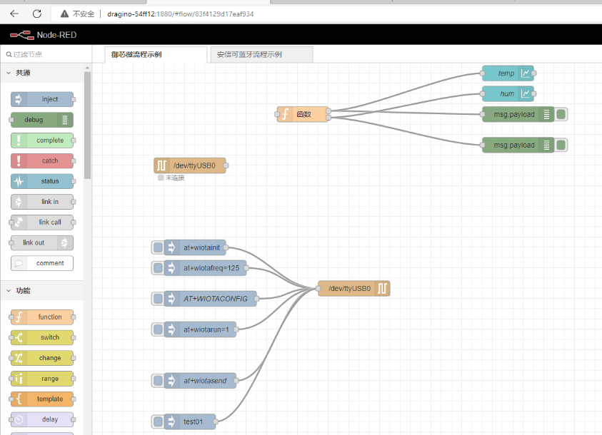
You can access the gateway's built-in AS server of Node-Red via the URL(http://<hostname>:1880 or http://<local-IPV4-address>) in your browser.
Such as http://dragino-54ff12:1880 or http://<Local-IPV4-Address>
Using Node-Red, InfluxDB and Grafana
The MS48-LR supports this combination, the default, Node-red is pre-installed but the InfluxDB and Grafana is not pre-installed.
the users can refer to this link to install them.
Upgrade the node.js
By default, the MS48-LR node.js uses the pre-install version v12 which is due to Debian the ultra-stable via ultra-old.
the users can refer to this link to upgrade them.
5. Use RS232 Interface
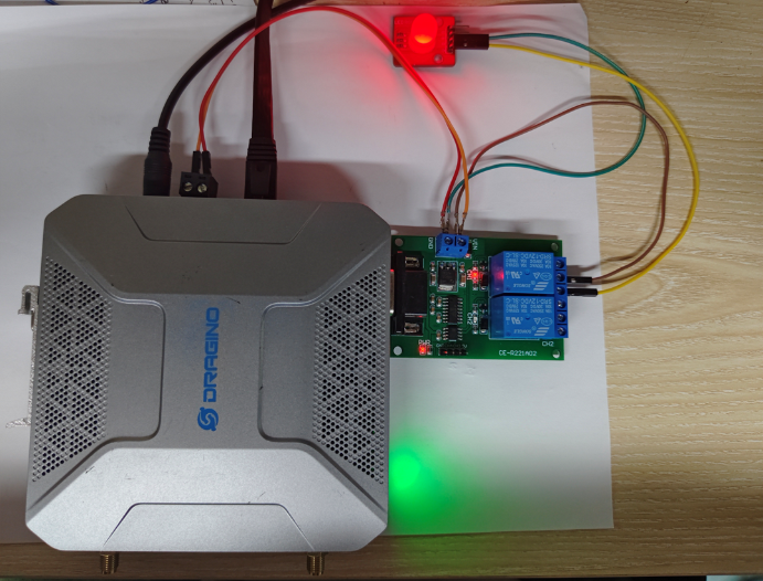
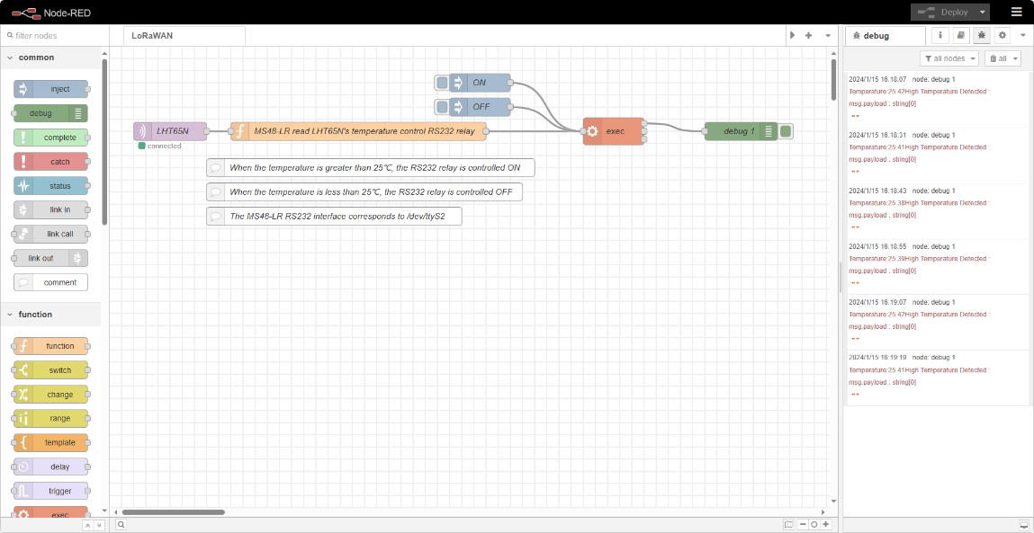
MS48-LR includes a local ChirpStack Server and Node-Red. This example shows how to configure LHT65N to use with the local Node-Red server. This example assumes users already have:
- LHT65N register on MS48-LR Built-In ChirpStack server already
- The user is able to see the data on the built-in ChirpStack server device page
- The RS232 relay is connected to the RS232 interface of the MS48-LR
The MS48-LR RS232 interface corresponds to /dev/ttyS2.
Below are the steps for the MS48-LR read LHT65N's temperature control RS232 relay example:

5.1 Link Node-Red to Local ChirpStack
Users can download the Node-Red decoder from this link and import it into the Node-Red platform:
For more information on importing Input Flow, check out this link: Import Input Flow for Dragino Sensors
After importing the Input Flow is complete, the user needs to edit the MQTT in the node
The specific steps can be found at this link: Example: Use Local Server ChirpStack and Node-Red
6. Use RS485 Interface
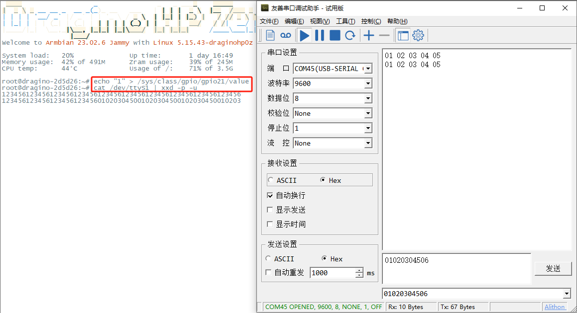
The MS48-LR RS485 interface corresponds to /dev/ttyS1.
Below are the steps for the MS48-LR RS485 interface to manually send and receive data:

6.1 Initialize the GPIO21
Users need to run the following command to configure GPIO21:
6.2 Set the RS485 Tx Mode
Set the MS48-LR RS485 port to Tx mode by lowering the GPIO21 level:
Run the following command to send hexadecimal data:

Users can use the serial port tool to check the data sent by MS48-LR RS485:

6.3 Set the RS485 Rx Mode
Set the MS48-LR RS485 port to Rx mode by pulling up the GPIO21 level:
Run the following command to check the data received by the MS48-LR RS485:
7. Power Analyze
Users can refer to and calculate the power consumption of the MS48-LR in this:
| Model | Input Power | Test Mode | Current(mA) | Power Consumption(W) |
|---|---|---|---|---|
| MS48-LR | (+12V) | |||
| Starting current | 90-190 | 1.080-2.280 | ||
| No network | 179-210 | 2.148-2.520 | ||
| wifi and internet connection(LORA Start) | 137-178 | 1.644-2.136 | ||
| wifi and internet connection(LORA Start) and 4G | 144-201 | 1.728-2.412 | ||
| wifi and internet connection(LORA Start) and 4G and 64g U disk | 172-225 | 2.100-2.700 | ||
| 4G connection(LORA Start) | 161-226 | 1.932-2.712 | ||
| wifi and internet connection(LORA Start) and 64g U disk | 162-193 | 1.956-2.316 | ||
| send manually | 377 | 4.524 | ||
| accept manually | 175 | 2.100 |
8. More Services
8.1 NTP Service/Time Synchronization
The gateway time sync service is provided by chrony service.
1). Modify the NTP server address:
2). Start/Stop/Enable/Disable NTP service:
8.2 Back up the built-in server data and Restore backup
The ms48-lr gateway has a built-in chirpstack server data backup function. Users can click "Generate_archive" on the System-->Back up/Restore Config page to generate a backup, and then download

Users can upload backup files on other MS48-LRs and upload server data to this gateway

In this way, users can migrate the data of the backup server to other MS48-LR gateways.
9. Trouble Shooting
9.1 Click "Manual_Update", why there is no response?
When you click "Manual_Update", the gateway will finish updating within 10 minutes and display the update log.

9.2 How to reset the built-in server
Users need to click "Reset" on the Server-->Network Server interface, ChirpStack will be reset.

9.3 How does modbus tcp downlink single-byte register contents to sensor devices
By default, each register occupies 16 bits (2 bytes). Therefore, when the client sends data such as 030101, it is necessary to directly add FFFFF in the single register, for example: 0x0301, 0xFFFF, 0xFF01,
the gateway will automatically convert it to 030101 downlink


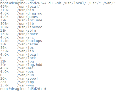
9.4 How to check the Storage of the gateway
Run the following command on the command line interface of the gateway to check the disk space usage:

On the Linux console of the gateway, enter the following command to check the total disk space occupied by the files running on the gateway:
9.4 How to clear the local server cache of the gateway using the command
10. Supports
If you are experiencing issues and can't solve them, you can send mail to support@dragino.com.
With your question as detailed as possible. We will reply and help you in the shortest.
11. Order Info
MS48-LR-XXX-YYY
XXX: Frequency Band
- AS923: LoRaWAN AS923 band
- AU915: LoRaWAN AU915 band
- EU868: LoRaWAN EU868 band
- KR920: LoRaWAN KR920 band
- US915: LoRaWAN US915 band
- IN865: LoRaWAN IN865 band
YYY: 4G Cellular Option
- EC25-E: EMEA, Korea, Thailand, India
- EC25-AFX: America:Verizon, AT&T(FirstNet), U.S.Cellular; Canada:Telus
- EC25-AUX: Latin America, New Zeland, Taiwan
- EC25-J: Japan, DOCOMO, SoftBank, KDDI
More info about valid bands, please see EC25-E product page.
12. Manufacturer Info
Shenzhen Dragino Technology Development co. LTD
Room 202, Block B, BCT Incubation Bases (BaoChengTai), No.8 CaiYunRoad
LongCheng Street, LongGang District ; Shenzhen 518116,China
13. FCC Warning
This equipment has been tested and found to comply with the limits for a Class B digital device, pursuant to Part 15 of the FCC Rules. These limits are designed to provide reasonable protection against harmful interference in a residential installation. This equipment generates uses and can radiate radio frequency energy and, if not installed and used in accordance with the instructions, may cause harmful interference to radio communications. However, there is no guarantee that interference will not occur in a particular installation. If this equipment does cause harmful interference to radio or television reception, which can be determined by turning the equipment off and on, the user is encouraged to try to correct the interference by one or more of the following measures:
-- Reorient or relocate the receiving antenna.
-- Increase the separation between the equipment and receiver.
-- Connect the equipment into an outlet on a circuit different from that to which the receiver is connected.
-- Consult the dealer or an experienced radio/TV technician for help.
Changes or modifications not expressly approved by the party responsible for compliance could void the user's authority to operate the equipment.
The antenna(s) used for this transmitter must be installed to provide a separation distance of at least 20 cm from all persons and must not be co-located or operating in conjunction with any other antenna or transmitter.
