TCP Connection Instruction
Table of Contents:
- 1. Introduction
- 2. LoRaWAN Mode TCP Connection
- 3. Raw LoRa Mode TCP Connection
- 4. Reference
1. Introduction
In the TCP IP Client mode, LoRa Gateway can accept LoRa or LoRaWAN packets and send it to the TCP/IP server.
2. LoRaWAN Mode TCP Connection
2.1 Support Hardware
2.2 Typology & Instruction

Network Structure
3. Raw LoRa Mode TCP Connection
3.1 Support Hardware
3.2 Typology
The working topology is as below. In this mode, The Uplink LoRa packets should use a customized format.
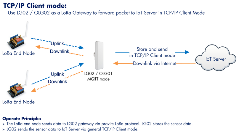
TCP/IP Forward working topology
3.3 Instruction Before Firmware lgw--build-v5.4.1606631585-20201129-1434
3.3.1 Select TCP-IP Client mode
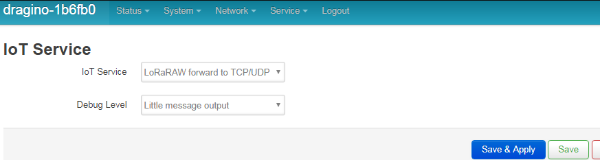
Select TCP-IP Client mode
3.3.2 Configure the Radio channel
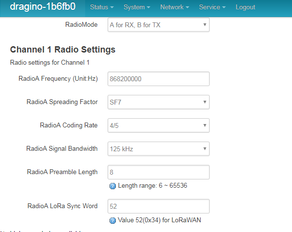
Configure the Radio channel with the match radio settings frequency as the LoRa End Node
3.3.3 Configure TCP Server Info
Note: Gateway may receive many LoRa packets, it will only transfer the packet with the same ID as specify in the channel.
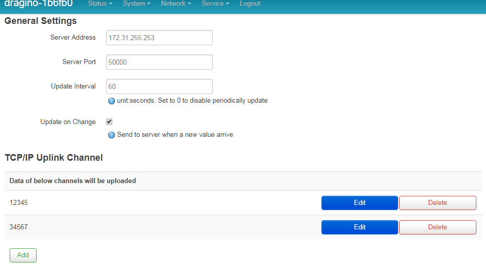
Configure TCP Server Info
3.3.4 About uplink data format from End Node
The LoRa end node should upload the data with below format:
Uplink Format: <Channel_ID>data
For example, if we have configured 2 channels 12345 and 34567.
And there is are three LoRa End nodes sending: 12345,34567,78
The LG02 will accept the data from 12345 and 34567, it will ignore the data from Node 78
Case 1:
Node 12345 send <12345>field1=0.0&field2=1102.0
Node 34567 doesn’t send anyting
The TCP/IP server will get {"12345":"field1=0.0&field2=1102.0"}
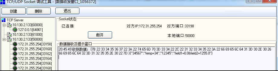
Case 2:
Node 12345 send <12345>field1=0.0&field2=1102.0
Node 34567 send <34567>temp=34
The TCP/IP server will get {"34567":"temp=34","12345":"field1=0.0&field2=1102.0"}
Configure TCP Server Info
LoRa End Device reference source code: check this link.
3.4 Instruction After Firmware lgw--build--v5.4.1612428704--20210204-1653
3.4.1 Configure the Radio channel
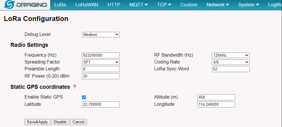
Configure the Radio channel with the match radio settings frequency as the LoRa End Node
3.4.2 Configure TCP Server Info
Note: Gateway will transfer the packet if they arrive in the right format .
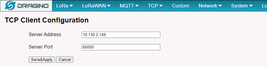
Configure TCP Server Info
3.4.3 About uplink data format from End Node
The LoRa end node should upload the data with below format:
Uplink Format: <Channel_ID>data
And there is a LoRa End node sending below packets:
*<12345>Hello From Sensor1
LG01/LG02 will uplink 12345:Hello From Sensor1 and usr can use logread -f to check the log.
Thu Feb 4 08:21:49 2021 user.notice iot_keep_alive: use WAN or WiFi for internet access now
Thu Feb 4 08:21:53 2021 daemon.info tcp_process.sh[18564]: /var/iot/channels/ CREATE 12345
Thu Feb 4 08:21:53 2021 user.notice root: [IoT.TCP]: Check for sensor update
Thu Feb 4 08:21:53 2021 user.notice root: [IoT.TCP]: Found Data at Local Channels: 12345
Thu Feb 4 08:21:53 2021 user.notice root: [IoT.TCP]:
Thu Feb 4 08:21:53 2021 user.notice root: [IoT.TCP]:-----
Thu Feb 4 08:21:53 2021 user.notice root: [IoT.TCP]:server: 10.130.2.149
Thu Feb 4 08:21:53 2021 user.notice root: [IoT.TCP]:port: 60000
Thu Feb 4 08:21:53 2021 user.notice root: [IoT.TCP]:decoder: LG01/LG02 Raw Data
Thu Feb 4 08:21:53 2021 user.notice root: [IoT.TCP]:tcp_data: 12345:Hello From Sensor1;
Thu Feb 4 08:21:53 2021 user.notice root: [IoT.TCP]:------
and TCP server get:
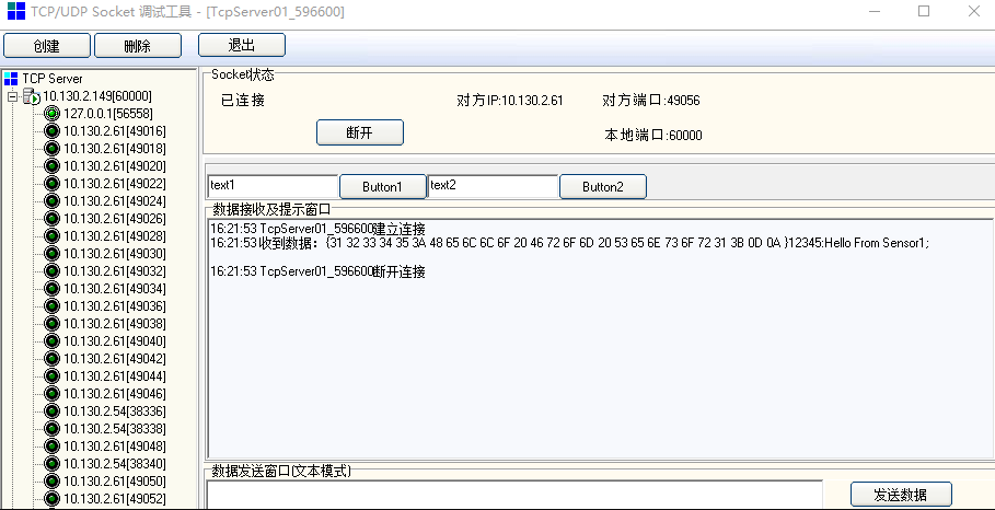
TCP Server
LoRa End Device reference source code: check this link.
3.5 Instruction After Firmware lgw--build-v5.4.1668567157-20221116-1054
3.5.1 Configure the Frequency Plan
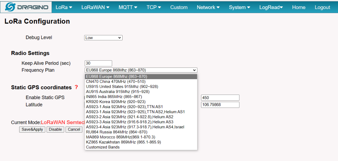
Configure the Frequency Plan with the match radio settings frequency as the LoRa End Node
3.5.2 Configure TCP Server Info
Note: Gateway will transfer the packet if they arrive in the right format.
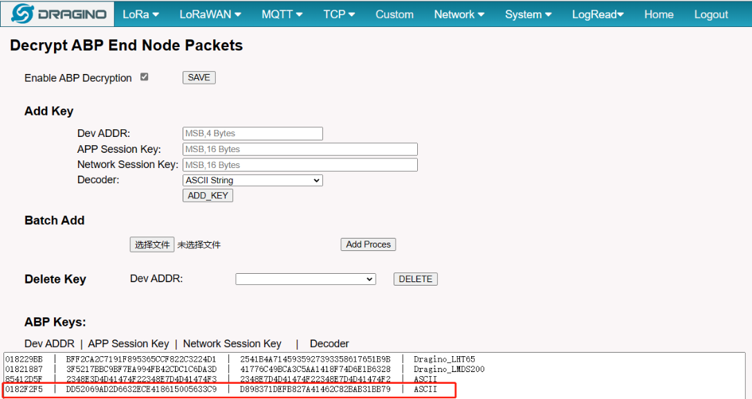
3.5.3 Configure ABP Decryption
Note: The End Node devices must use ABP join network mode.
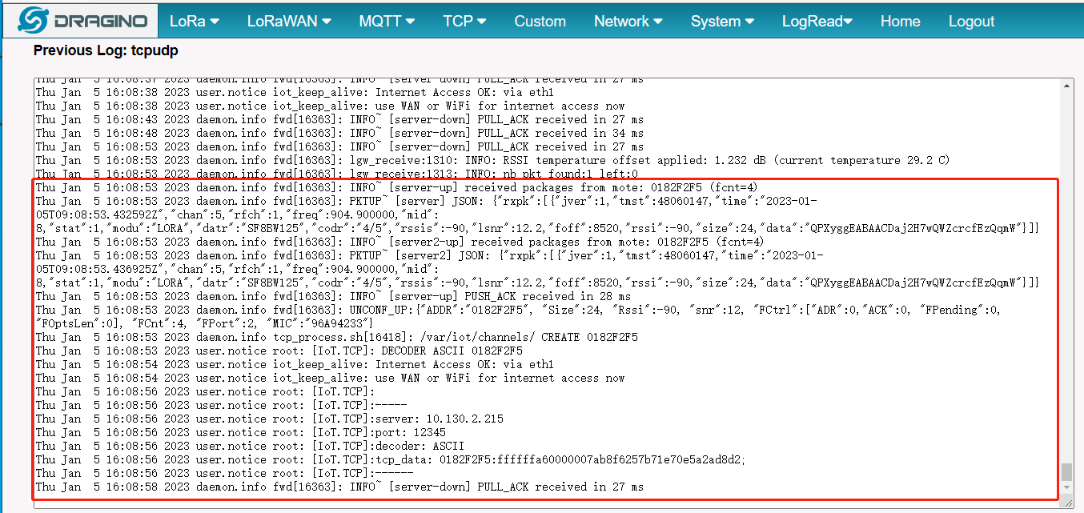
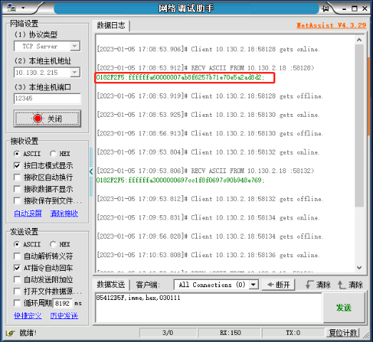
3.5.4 About uplink data format from End Node
3.6 Example: Use TCP in LPS8v2
LPS8v2 includes a local ChirpStack Server and Node-Red. This example shows how to configure LHT65N to use with the local Node-Red server. This example assumes users already have:
- LHT65N register on LPS8v2 Built-In ChirpStack server already
- The user is able to see the data on the built-in ChirpStack server device page.
Below are steps for LPS8v2 to transfer data from a node to the TCP server.
3.6.1 Link Node-Red to Local ChirpStack
Users can download the Node-Red decoder from this link and import it into the Node-Red platform:
For more information on importing Input Flow, check out this link: Import Input Flow for Dragino Sensors
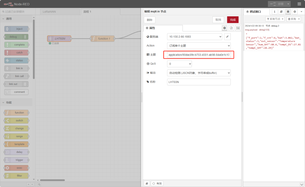
After importing the Input Flow is complete, the user needs to edit the MQTT in the node
1. Change the Topic
Topic modifies it to the following format:
application/Application ID/device/End device ID/event/up
Reference link: Node-RED integration
2. Enter the MQTT configuration information
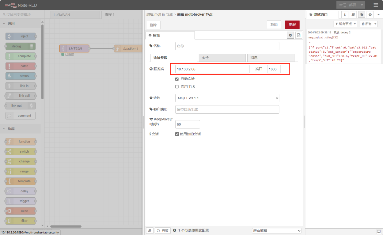
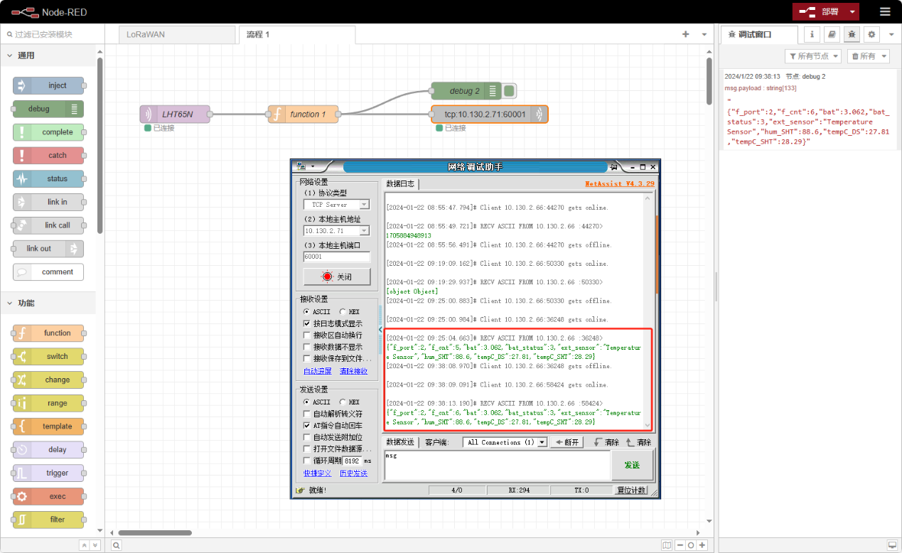
3. Click "Update" and Deploy
"Connected" indicates that the Link Node-red to Local Chirpstack is normal.
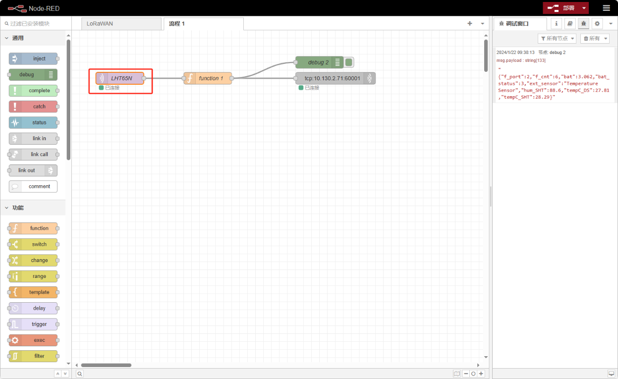
4. Connect to the TCP server
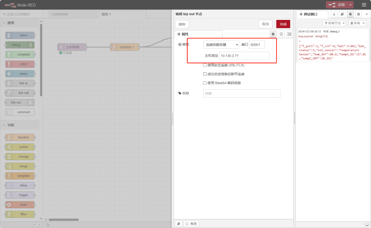
5. Finally, check the data
4. Reference
Set up a TCP/IP server use node.js: Reference Link