Cellular network connection details and tips
Table of Contents:
- 1. Enable Cellular Connection
- 2. How to Trouble Shooting if Cellular connection fails
- 2.1 For LPS8N/DLOS8N/LG308N
- 2.1.1 Do you order the model with a cellular option
- 2.2 For LPS8v2/MS48-LR
- 2.3 If the following situation occurs, how can users solve this problem?
- 2.3.1 The gateway can read the SIM card, But the Internet is displayed as Fail.
- 2.3.2 The gateway can read the SIM card, But the Internet is displayed as Fail, and at the same time Network displays the carrier network.
- 2.3.3 The gateway can't read the SIM card, and the Internet is displayed as Fail.
- 2.3.4 SIM display:***SIM ERROR*** Check SIM is inserted test SIM in a mobile phone?
- 3. Share Cellular Network for WiFi & LAN clients
- 4. Switching between Cellular and Ethernet and Wi-Fi networks
- 5. How does the gateway view the International Mobile Equipment Identity (IMEI)
- For LIG16,LPS8, LPS8N, LG308, LG308N, DLOS8, DLOS8N view the International Mobile Equipment Identity (IMEI)
- For LPS8v2 view the International Mobile Equipment Identity (IMEI)
- How does the gateway access the Quetel module directly (to send AT commands)
- International Mobile Equipment Identity (IMEI)
- Integrated Circuit Card Identifier (ICCID)
- 6. How does the gateway connect to the network via a USB 4G Dongle
- 7. How to reduce data traffic
1. Enable Cellular Connection
If your device has a Cellular module, you can see the below screenshot. enable the cellular connection here.
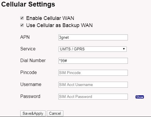
Enable Cellular Connection
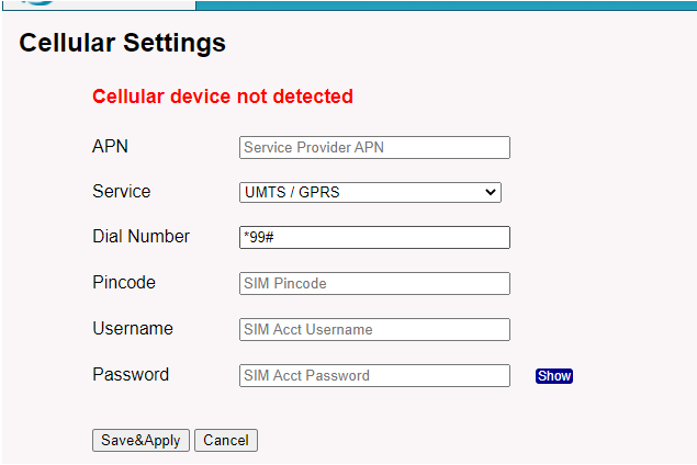
If your device doesn't have a cellular module, you will see a cellular module not detected.
2. How to Trouble Shooting if Cellular connection fails
If there is a problem with the cellular connection. Please check the below points:
2.1 For LPS8N/DLOS8N/LG308N
2.1.1 Do you order the model with a cellular option
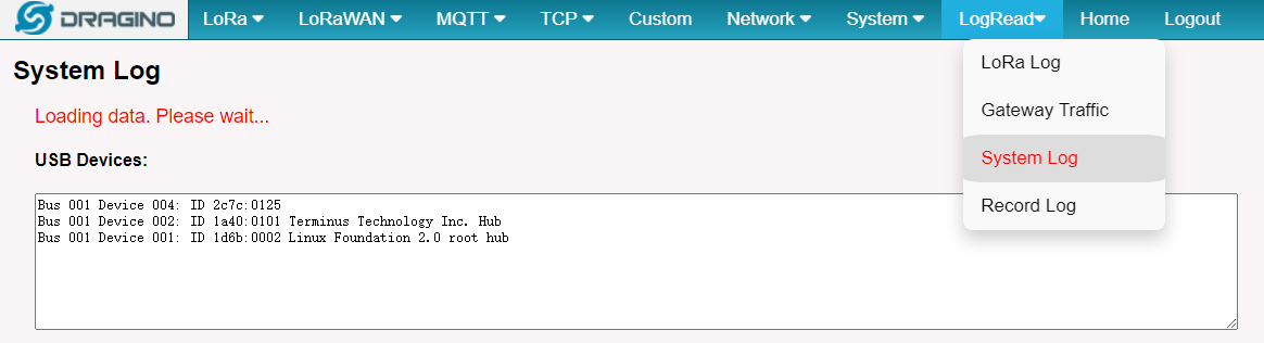
Make sure you order the model with the cellular option. Can check by command or via the Web UI.
root@dragino-1bbd90:~# lsusb
Bus 001 Device 004: ID 2c7c:0125 --> This is the Cellular module
Bus 001 Device 002: ID 1a40:0101 Terminus Technology Inc. Hub
Bus 001 Device 001: ID 1d6b:0002 Linux Foundation 2.0 root hub
2.1.2 Do you input the SIM card correctly
Below command can check if you have a SIM card inserted, or via Web UI
- Make sure to Power Off when you insert the SIM card and power on the device. The device doesn't support auto-detect SIM card on power on
- Make sure you have the correct direction to insert the SIM card. Every device has an example photo in the manual for the direction.
For Models: LPS8N, LG308N, DLOS8N
root@dragino-1dadd8:~# comgt -d /dev/ttyUSB3
SIM ready
Waiting for Registration..(120 sec max)
Registered on Home network: "CHN-UNICOM",7
Signal Quality: 10,99
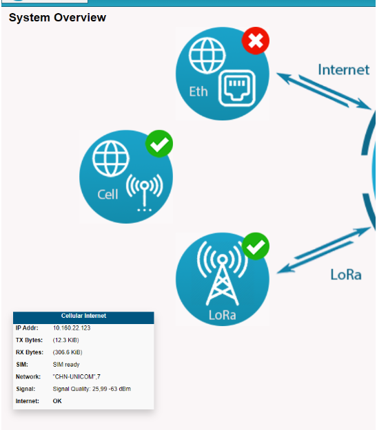
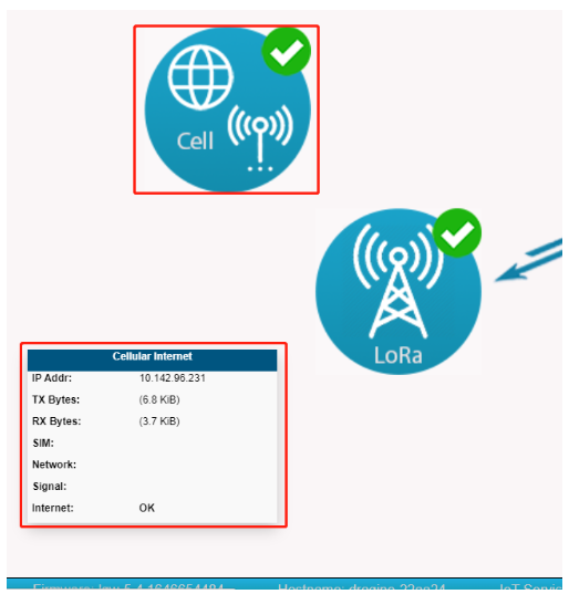
Note: If the icon is missing some information, like SIM, Network, or Signal, which may be due to the display bug.
Please check the IP address is displayed and the Internet displays "OK", it works properly.
2.1.3 Check dialing info
run "logread -f" in gateway CLI。
Fri Feb 7 01:20:28 2020 daemon.notice pppd[29452]: pppd 2.4.7 started by root, uid 0
Fri Feb 7 01:20:29 2020 user.notice iot_keep_alive: Ping WAN
Fri Feb 7 01:20:29 2020 user.notice iot_keep_alive: Default interface is
Fri Feb 7 01:20:29 2020 user.notice iot_keep_alive: No internet at any interface
Fri Feb 7 01:20:29 2020 local2.info chat[29485]: abort on (BUSY)
Fri Feb 7 01:20:29 2020 local2.info chat[29485]: abort on (NO CARRIER)
Fri Feb 7 01:20:29 2020 local2.info chat[29485]: abort on (ERROR)
Fri Feb 7 01:20:29 2020 local2.info chat[29485]: report (CONNECT)
Fri Feb 7 01:20:29 2020 local2.info chat[29485]: timeout set to 10 seconds
Fri Feb 7 01:20:29 2020 local2.info chat[29485]: send (AT&F^M)
Fri Feb 7 01:20:29 2020 local2.info chat[29485]: expect (OK)
Fri Feb 7 01:20:29 2020 local2.info chat[29485]: AT&F^M^M
Fri Feb 7 01:20:29 2020 local2.info chat[29485]: OK
Fri Feb 7 01:20:29 2020 local2.info chat[29485]: -- got it
Fri Feb 7 01:20:29 2020 local2.info chat[29485]: send (ATE1^M)
Fri Feb 7 01:20:29 2020 local2.info chat[29485]: expect (OK)
Fri Feb 7 01:20:29 2020 local2.info chat[29485]: ^M
Fri Feb 7 01:20:29 2020 local2.info chat[29485]: ATE1^M^M
Fri Feb 7 01:20:29 2020 local2.info chat[29485]: OK
Fri Feb 7 01:20:29 2020 local2.info chat[29485]: -- got it
Fri Feb 7 01:20:29 2020 local2.info chat[29485]: send (AT+CGDCONT=1,"IP",""^M)
Fri Feb 7 01:20:30 2020 local2.info chat[29485]: timeout set to 30 seconds
Fri Feb 7 01:20:30 2020 local2.info chat[29485]: expect (OK)
Fri Feb 7 01:20:30 2020 local2.info chat[29485]: ^M
Fri Feb 7 01:20:30 2020 local2.info chat[29485]: AT+CGDCONT=1,"IP",""^M^M
Fri Feb 7 01:20:30 2020 local2.info chat[29485]: OK
Fri Feb 7 01:20:30 2020 local2.info chat[29485]: -- got it
Fri Feb 7 01:20:30 2020 local2.info chat[29485]: send (ATD*99#^M) -----> In case the dialling process already reach here.
Normally the problem is with a provider, need to check if the SIM card has balance or other requirement from the cellular operator
Fri Feb 7 01:20:30 2020 local2.info chat[29485]: expect (CONNECT)
Fri Feb 7 01:20:30 2020 local2.info chat[29485]: ^M
Fri Feb 7 01:20:30 2020 local2.info chat[29485]: ATD*99#^M^M
Fri Feb 7 01:20:30 2020 local2.info chat[29485]: CONNECT
Fri Feb 7 01:20:30 2020 local2.info chat[29485]: -- got it
Fri Feb 7 01:20:30 2020 local2.info chat[29485]: send ( ^M)
Fri Feb 7 01:20:30 2020 daemon.info pppd[29452]: Serial connection established.
2.2 For LPS8v2/MS48-LR
2.2.1 Do you order the model with a cellular option
Make sure you order the model with the cellular option. Can check by command or via the Web UI.
root@dragino-2d5d26:~# lsusb
Bus 008 Device 001: ID 1d6b:0001 Linux Foundation 1.1 root hub
Bus 004 Device 002: ID 2c7c:0125 Quectel Wireless Solutions Co., Ltd. EC25 LTE modem --> This is the Cellular module
Bus 004 Device 001: ID 1d6b:0002 Linux Foundation 2.0 root hub
Bus 007 Device 001: ID 1d6b:0001 Linux Foundation 1.1 root hub
Bus 003 Device 001: ID 1d6b:0002 Linux Foundation 2.0 root hub
Bus 006 Device 001: ID 1d6b:0001 Linux Foundation 1.1 root hub
Bus 002 Device 001: ID 1d6b:0002 Linux Foundation 2.0 root hub
Bus 005 Device 001: ID 1d6b:0001 Linux Foundation 1.1 root hub
Bus 001 Device 002: ID 0bda:f179 Realtek Semiconductor Corp. RTL8188FTV 802.11b/g/n 1T1R 2.4G WLAN Adapter
Bus 001 Device 001: ID 1d6b:0002 Linux Foundation 2.0 root hub
Bus 009 Device 001: ID 1d6b:0002 Linux Foundation 2.0 root hub
root@dragino-2d5d26:~#


Note: If the icon is missing some information, like SIM, Network, or Signal, which may be due to the display bug.
Please check the IP address is displayed and the Internet displays "OK", it works properly.

2.2.2 Check cellular info
Below command can check if you have a SIM card inserted, or via Web UI
- Make sure to Power Off when you insert the SIM card and power on the device. The SIM card slot of the gateway does not support hot swap
- Make sure you have the correct direction to insert the SIM card. Every device has an example photo in the manual for the direction.

run "quectel-CM" in gateway CLI
The gateway cellular logs show SIMStatus: SIM_ABSENT
If the SIM status is SIM_ABSENT, the SIM card is not detected. You need to check whether the SIM card is available and whether the device is powered off when the SIM card is installed.
root@dragino-2d5d26:~# quectel-CM -s 3gnet
[12-05_07:12:08:451] Quectel_QConnectManager_Linux_V1.6.0.24
[12-05_07:12:08:454] Find /sys/bus/usb/devices/4-1 idVendor=0x2c7c idProduct=0x125, bus=0x004, dev=0x002
[12-05_07:12:08:455] Auto find qmichannel = /dev/cdc-wdm0
[12-05_07:12:08:455] Auto find usbnet_adapter = wwan0
[12-05_07:12:08:455] netcard driver = qmi_wwan, driver version = 5.15.43-draginohp0z
[12-05_07:12:08:456] Modem works in QMI mode
[12-05_07:12:08:516] cdc_wdm_fd = 7
[12-05_07:12:08:613] Get clientWDS = 21
[12-05_07:12:08:645] Get clientDMS = 1
[12-05_07:12:08:676] Get clientNAS = 4
[12-05_07:12:08:709] Get clientUIM = 2
[12-05_07:12:08:741] Get clientWDA = 1
[12-05_07:12:08:774] requestBaseBandVersion EC25EFAR06A16M4G
[12-05_07:12:08:902] requestGetSIMStatus SIMStatus: SIM_ABSENT -----> This means that the SIM cannot be read
[12-05_07:12:08:902] requestSetProfile[1] 3gnet///0
[12-05_07:12:08:965] requestGetProfile[1] 3gnet///0
[12-05_07:12:08:997] requestRegistrationState2 MCC: 0, MNC: 0, PS: Detached, DataCap: UNKNOW
[12-05_07:12:09:030] requestQueryDataCall IPv4ConnectionStatus: DISCONNECTED
[12-05_07:12:09:030] ifconfig wwan0 0.0.0.0
[12-05_07:12:09:043] ifconfig wwan0 down
^C[12-05_07:12:18:311] QmiWwanThread exit
[12-05_07:12:18:313] qmi_main exit
The gateway cellular logs show SIMStatus: SIM_PIN
If the SIM status is SIM_PIN, it means that the SIM card is read but the Pincode needs to be filled in.
root@dragino-2d5d26:~# quectel-CM -s 3gnet
[10-31_12:17:10:166] Find /sys/bus/usb/devices/2-1 idVendor=0x2c7c idProduct=0x125, bus=0x002, dev=0x002
[10-31_12:17:10:168] Auto find qmichannel = /dev/cdc-wdm0
[10-31_12:17:10:168] Auto find usbnet_adapter = wwan0
[10-31_12:17:10:168] netcard driver = qmi_wwan, driver version = 5.15.43-draginohp0z
[10-31_12:17:10:170] Modem works in QMI mode
[10-31_12:17:10:234] cdc_wdm_fd = 8
[10-31_12:17:10:325] Get clientWDS = 21
[10-31_12:17:10:356] Get clientDMS = 1
[10-31_12:17:10:389] Get clientNAS = 4
[10-31_12:17:10:449] Get clientUIM = 2
[10-31_12:17:10:489] Get clientWDA = 1
[10-31_12:17:10:518] requestBaseBandVersion EC25EFAR06A16M4G
[10-31_12:17:10:645] requestGetSIMStatus SIMStatus: SIM_PIN -----> This means you need to fill in the Pincode
[10-31_12:17:10:645] requestSetProfile[1] Telekom///0
[10-31_12:17:10:713] requestGetProfile[1] Telekom///0
[10-31_12:17:10:743] requestRegistrationState2 MCC: 262, MNC: 2, PS: Detached, DataCap: UNKNOW
[10-31_12:17:10:773] requestQueryDataCall IPv4ConnectionStatus: DISCONNECTED
[10-31_12:17:10:774] ifconfig wwan0 0.0.0.0
[10-31_12:17:10:790] ifconfig wwan0 down
[10-31_18:27:35:797] QmiWwanThread exit
[10-31_18:27:35:798] qmi_main exit
The gateway cellular logs show SIMStatus: SIM_READY
If the SIM status is SIM_READY, it means that the SIM card is detected
root@dragino-2d5d26:~# quectel-CM -s 3gnet
[12-05_07:32:57:187] Quectel_QConnectManager_Linux_V1.6.0.24
[12-05_07:32:57:191] Find /sys/bus/usb/devices/4-1 idVendor=0x2c7c idProduct=0x125, bus=0x004, dev=0x002
[12-05_07:32:57:192] Auto find qmichannel = /dev/cdc-wdm0
[12-05_07:32:57:193] Auto find usbnet_adapter = wwan0
[12-05_07:32:57:198] netcard driver = qmi_wwan, driver version = 5.15.43-draginohp0z
[12-05_07:32:57:199] Modem works in QMI mode
[12-05_07:32:57:261] cdc_wdm_fd = 7
[12-05_07:32:57:334] Get clientWDS = 20
[12-05_07:32:57:366] Get clientDMS = 1
[12-05_07:32:57:398] Get clientNAS = 4
[12-05_07:32:57:431] Get clientUIM = 1
[12-05_07:32:57:462] Get clientWDA = 1
[12-05_07:32:57:495] requestBaseBandVersion EC25EFAR06A16M4G
[12-05_07:32:57:623] requestGetSIMStatus SIMStatus: SIM_READY
[12-05_07:32:57:655] requestGetProfile[1] 3gnet///0
[12-05_07:32:57:687] requestRegistrationState2 MCC: 460, MNC: 15, PS: Detached, DataCap: UNKNOW
[12-05_07:32:57:719] requestQueryDataCall IPv4ConnectionStatus: DISCONNECTED
[12-05_07:32:57:719] ifconfig wwan0 0.0.0.0
[12-05_07:32:57:731] ifconfig wwan0 down
[12-05_07:33:00:727] requestRegistrationState2 MCC: 0, MNC: 0, PS: Detached, DataCap: UNKNOW
[12-05_07:33:15:895] requestRegistrationState2 MCC: 460, MNC: 0, PS: Detached, DataCap: UNKNOW
[12-05_07:33:19:063] requestRegistrationState2 MCC: 460, MNC: 0, PS: Detached, DataCap: EDGE
[12-05_07:33:19:095] requestRegistrationState2 MCC: 460, MNC: 0, PS: Detached, DataCap: EDGE
[12-05_07:33:21:463] requestRegistrationState2 MCC: 460, MNC: 0, PS: Attached, DataCap: EDGE
[12-05_07:33:22:359] requestSetupDataCall WdsConnectionIPv4Handle: 0x8728b3d0
[12-05_07:33:22:488] ifconfig wwan0 up
[12-05_07:33:22:504] busybox udhcpc -f -n -q -t 5 -i wwan0
udhcpc: started, v1.30.1
udhcpc: sending discover
udhcpc: sending discover
udhcpc: sending discover
udhcpc: sending discover
udhcpc: sending discover
udhcpc: no lease, failing
[12-05_07:33:38:103] File:ql_raw_ip_mode_check Line:136 udhcpc fail to get ip address, try next:
[12-05_07:33:38:103] ifconfig wwan0 down
[12-05_07:33:38:116] echo Y > /sys/class/net/wwan0/qmi/raw_ip
[12-05_07:33:38:117] ifconfig wwan0 up
[12-05_07:33:38:130] busybox udhcpc -f -n -q -t 5 -i wwan0
udhcpc: started, v1.30.1
udhcpc: sending discover
udhcpc: sending select for 10.171.60.177
udhcpc: lease of 10.171.60.177 obtained, lease time 7200
2.3 If the following situation occurs, how can users solve this problem?
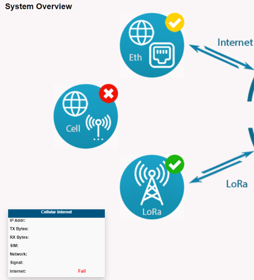
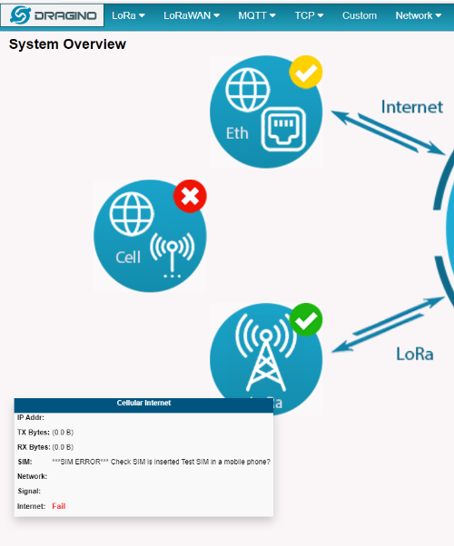
2.3.1 The gateway can read the SIM card, But the Internet is displayed as Fail.
Users can check whether the APN matched by the SIM card is correct.
Regarding what APN your SIM card should use, Users can search for the APN corresponding to the SIM card by Google or ask the carrier.
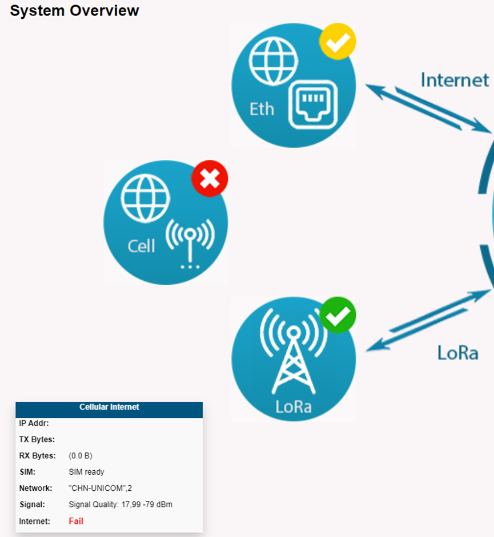
2.3.2 The gateway can read the SIM card, But the Internet is displayed as Fail, and at the same time Network displays the carrier network.
It should be SIM card no flow, users can insert SIM cards into the mobile phone for testing.
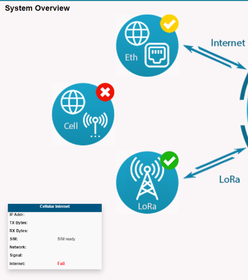
2.3.3 The gateway can't read the SIM card, and the Internet is displayed as Fail.
Users need to check whether the SIM card type is suitable for the EC25 module.
2.3.4 SIM display:***SIM ERROR*** Check SIM is inserted test SIM in a mobile phone?
Users can insert SIM cards into the mobile phone for testing.
3. Share Cellular Network for WiFi & LAN clients
By default, the Cellular Network won't be shared with the WiFi or LAN clients. If users need to share with them, the user can modify the file.
root@dragino-1d25dc:~# cat /etc/config/firewall
config defaults
option syn_flood '1'
option input 'ACCEPT'
option output 'ACCEPT'
option forward 'REJECT'
config zone
option name 'lan'
list network 'lan'
option input 'ACCEPT'
option output 'ACCEPT'
option forward 'REJECT'
config zone
option name 'wan'
list network 'wan'
list network 'wwan'
list network 'wan6'
list network 'cellular' -----------------> Add this line and reboot
option input 'REJECT'
option output 'ACCEPT'
option forward 'ACCEPT'
option masq '1'
option mtu_fix '1'
config forwarding
option src 'lan'
option dest 'wan'
and run /etc/init.d/firewall reload or reboot the device.
4. Switching between Cellular and Ethernet and Wi-Fi networks
By default, Cell is the backup WAN where the Ethernet or Wi-Fi network is used first if they are available.
Once the Ethernet of the Wi-Fi network is unavailable where the gateway network will switch to a Cell network from Ethernet or Wi-Fi.
Enable Cellular and connect Ethernet at the same time
ETH icon is displayed as ![]() Indicates that Ethernet is the main working network.
Indicates that Ethernet is the main working network.
Cell icon is displayed as ![]() Indicates that Cellular is the backup WAN.
Indicates that Cellular is the backup WAN.
4.1 Switching between Cellular and Ethernet networks
When connecting to the AP WiFI of the gateway, users can access the Web UI of the gateway through the default address 10.130.1.1
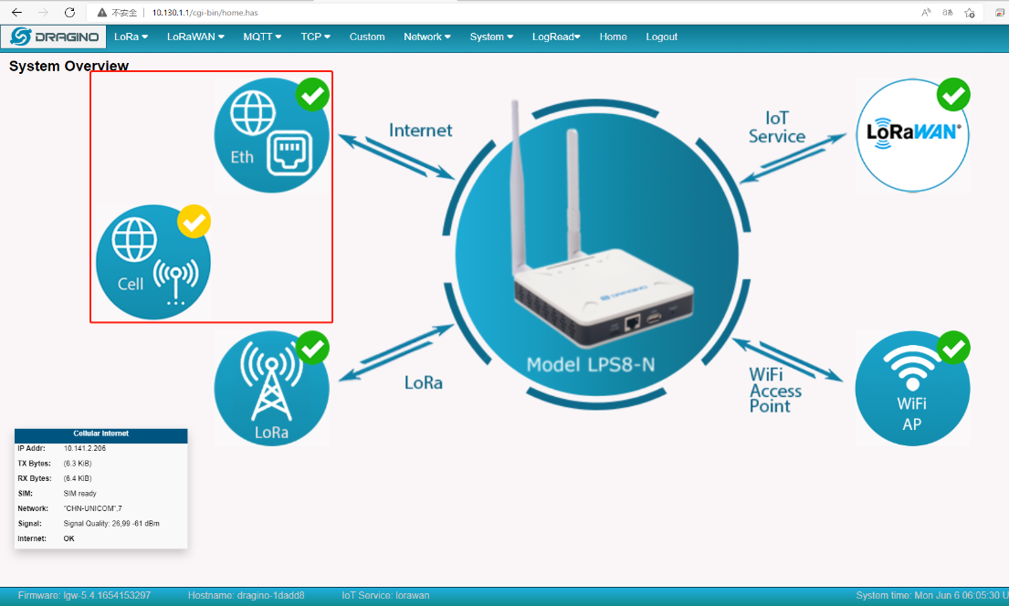
Remove the network cable from the WAN port on the gateway, the gateway will switch to a Cellular network.
4.2 Switching between Cellular and WiFi networks
Enable Cellular and connect WiFi at the same time
WiFi icon is displayed as ![]() Indicates that WiFi is the main working network.
Indicates that WiFi is the main working network.
Cell icon is displayed as ![]() Indicates that Cellular is the backup WAN.
Indicates that Cellular is the backup WAN.
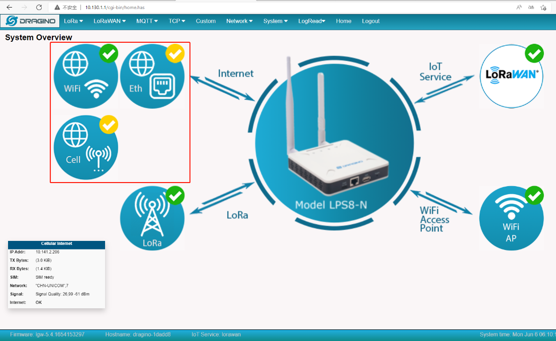
Close the WiFi WAN, the gateway will switch to a Cellular network.

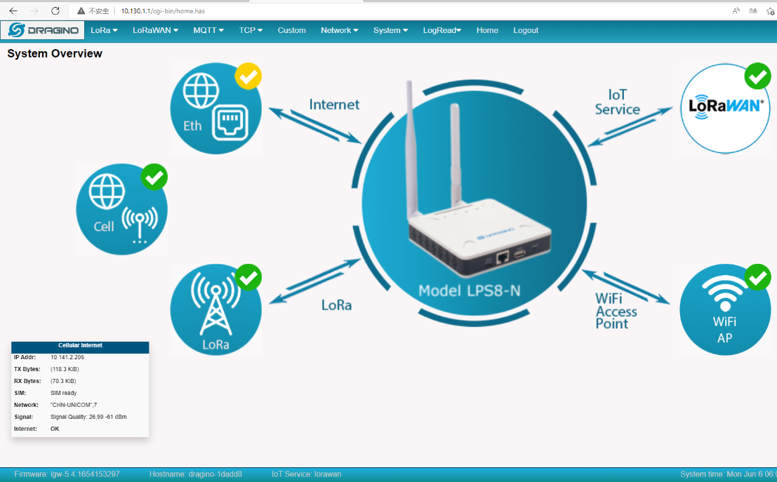
4.3 At the same time start Cellular and Ethernet and Wi-Fi networks

5. How does the gateway view the International Mobile Equipment Identity (IMEI)
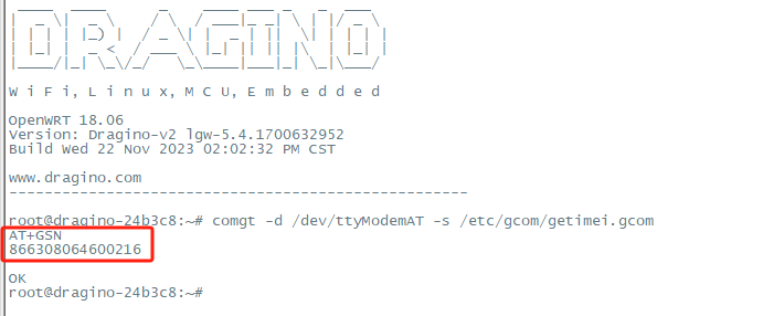
For LIG16,LPS8, LPS8N, LG308, LG308N, DLOS8, DLOS8N view the International Mobile Equipment Identity (IMEI)
Users can get the IMEI via Linux command, but you have to access the gateway CLI.
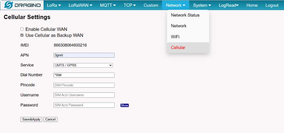
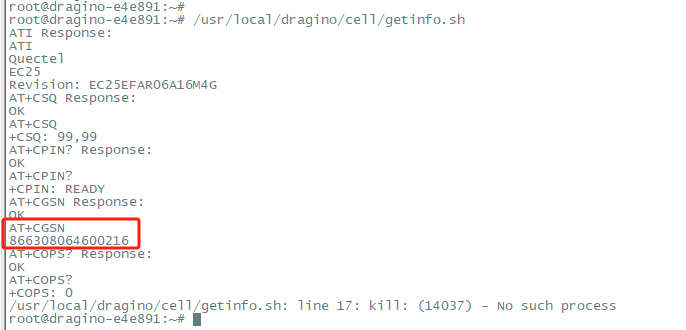
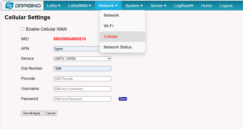
For LPS8v2 view the International Mobile Equipment Identity (IMEI)
How does the gateway access the Quetel module directly (to send AT commands)
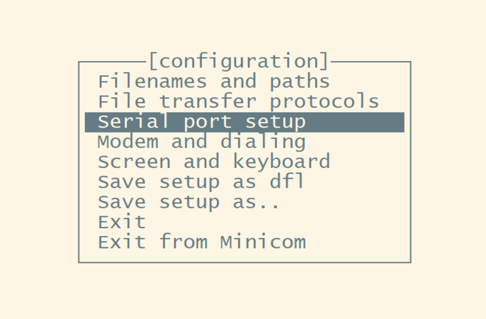
Users can access the gateway CLI and run the minicom command to get the configuration interface.
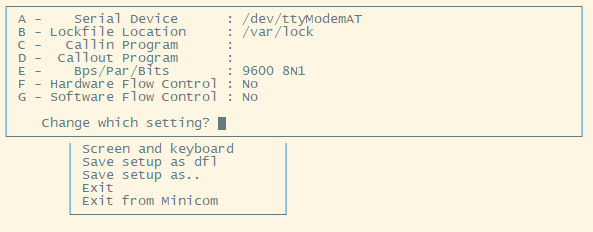
Enter the minicom command, then select the option ''serial port setup".
And then, change the setting:
Note: Enter the corresponding letter to change the configuration, like A,B,C
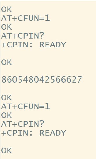
International Mobile Equipment Identity (IMEI)
Enter AT+GSN in the interface to get the IMEI,
For example: 860548042566627
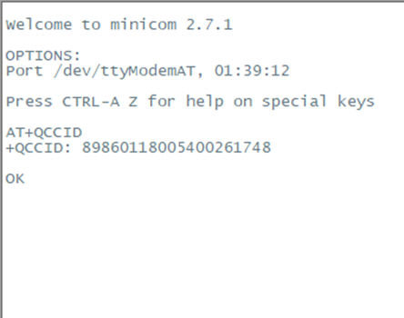
Integrated Circuit Card Identifier (ICCID)
Enter AT+QCCID in the interface to get the ICCID,
For example: 89860118005400261748
6. How does the gateway connect to the network via a USB 4G Dongle
6.1 Introduction
Prerequisite: Requires a USB 4G Dongle and a supported gateway firmware
This introduces a setup and configured gateway for using a USB 3g/UMTS-modem for WAN connection.
Many modes (and most LTE) USB modems provide qmi, mbim, ncm, rndis protocol for connection instead of legacy ppp protocol, they are faster and better, overall recommended.
This is not beginner-friendly due to too many protocols.
For more information: https://openwrt.org/docs/guide-user/network/wan/wwan/3gdongle
6.2 How to use the USB Dongle at the gateway
Most of the products can be used on the gateway, but because their protocols are different, they are not used in the same way.
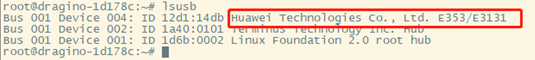
For example, the Huawei-E3372/E8372 is using Hilink mode or NCM mode.
Huawei-E3372/E8372
Check the E3372 version to determine the mode.
The version numbers starting with 21 is NCM mode
The version numbers starting with 22 is Hilink mode
The E8372 only has Hilink mode
Note: The e3372 in the vast majority of cases is Hilink mode
6.3 Hilink mode
Gateway upgrade to the specified firmware:Hilink.mode--build-v5.4.1625627505
6.3.1 Plugs into the device
USB-Dongle plugs into the gateway USB port
Check the USB module via command lsusb
Note: Users need to that connect to the gateway command line via ssh.
6.3.2 Detection of new network interfaces added
Check network configuration command line input:
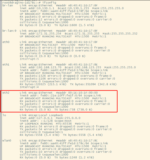
In the command, the output user can see that the new interface added is eth2
Usually, the user can see that the new interface added is eth2 or wwan0
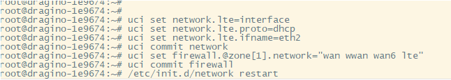
6.3.3 Add the new interface to the network configuration.
Enter the configuration from the command line:
uci set network.lte=interface
uci set network.lte.proto=dhcp
uci set network.lte.ifname=eth2 --------->#This depend on the name of the new interface gateway add
uci commit network
uci set firewall.@zone[1].network="wan wwan wan6 lte"
uci commit firewall
/etc/init.d/network restart
Checking Network Configurations
Command-line input: ifconfig
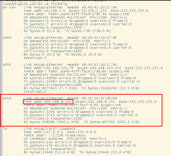
Now, Gateway is configured to access the internet on the LTE network.
6.4 NCM mode
6.5 Troubleshooting
6.5.1 The USB-Dongle interface cannot obtain the IP address.
Please try this USB dongle to access the internet on your PC, to make sure this USB dongle can normally access the internet.
7. How to reduce data traffic
7.1 How the gateway will consume data traffic
Below list the place where the data traffic will use.
- Valid uplink data to LoRaWAN server or IoT server. ( We can't reduce this as they are the data we want)
- Invalid uplink sensor data to LoRaWAN serevr. ( See Filter unwanted packets)
- LoRaWAN Status push or polling data to LoRaWAN server . ( We can reduce this part , see below for discussion)
- System Keep Alive data. ( To ensure the system is more robust, can be disabled)
- system Time synchronization Checking
- Auto update ( Software auto update, can be disabled)
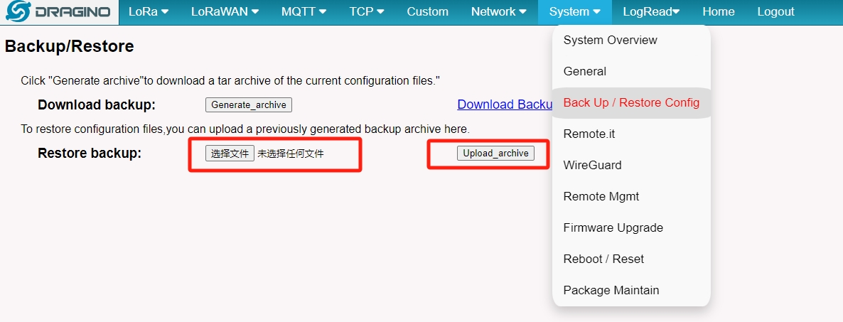
7.1.1 Uploading backup files to reduced data consumption
Users can upload this backup file to reduce data consumption in System-->Back Up/Restore Config, Download link for backup file:
7.1.2 Auto update
Gateway will check for update every day for new configure or software. User can disable them by below method.
7.1.3 Filter unwanted packets
When gateway connect to LoRaWAN server via LoRaWAN protocol , Gateway will by default get every possible LoRaWAN packets and forward to LoRaWAN server. If there are sensors from others in the same area, such sensor data will also be forward to LoRaWAN server ( they will be ignore by the server). This also consume data.
See How to filter unwanted packets
7.2 Usage statistics
7.2.1 How does Openwrt usage statistics
This is a general instruction for the use of Openwrt of Dragino devices. Current models include:
- LPS8,LPS8N
- LG308,LG308N
- DLOS8,DLOS8N
- LIG16
1. Activate LuCI and connect to SSH following these instructions
2. Install luci-app-statistics using the following terminal commands:
opkg update
opkg install luci-app-statistics
opkg install collectd-mod-interface
/etc/init.d/collectd enable
reboot
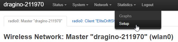
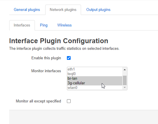
3. Select the interface to be monitored by going to Statistics > Setup in the upper menu then Network plugins > Interfaces. Select 3g-cellular in the list then save. You can select multiple interfaces by pressing the ctrl key while selecting the interfaces.
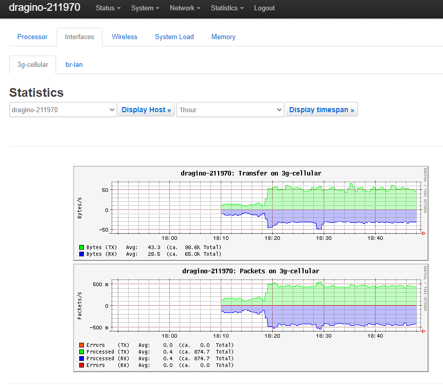
4. View the graphs and statistics using by going to Statistics > Graphs > Interfaces > 3g-cellullar
7.2.2 Gateway Traffic Usage Table
| Function | Conditions | Uplink Data / Per Day | Downlink Data / Per Day |
|---|---|---|---|
| LoRaWAN Connection (No Uplink Packets) | Semtech UDP /Default settings | ||
| LoRaWAN Connection (No Uplink Packets) | Basic Station /Default settings | ||
| Uplink Packets | 2000 packets (each 11 Bytes Paylaod) | ||
| Dragino Gateway Platform connection | Default settings | 1656kB | 846kB |
| IoT Keep Alive Script | Default Settings |