Node-RED_Install and Use
Table of Contents:
- 1. Installation
- 2. General Use of Node-RED
- 3. Import Input Flow for Dragino Sensors
- 4. Add Dragino node
- 5. FAQ
1. Installation
Check installation instruction for different OS from this link: https://nodered.org/docs/getting-started/
1.1 Install Example for CENTOS
1.1.1 Installation
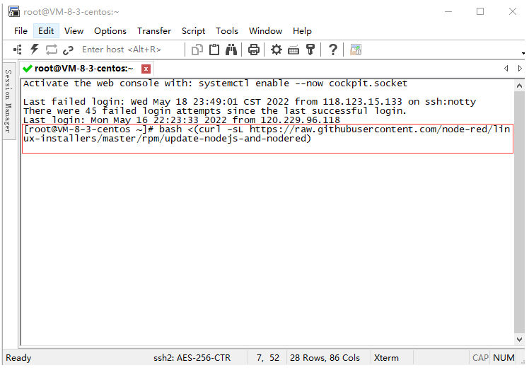
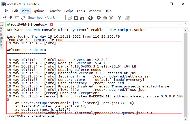
Verify if the installation was successful
Type in the command line interface node-red
The following information appears to prove that the installation has been successful
1.1.2 If you want to start Node-RED as a background process
Type in the command line interface nohup node-red &
It will prompt after startup
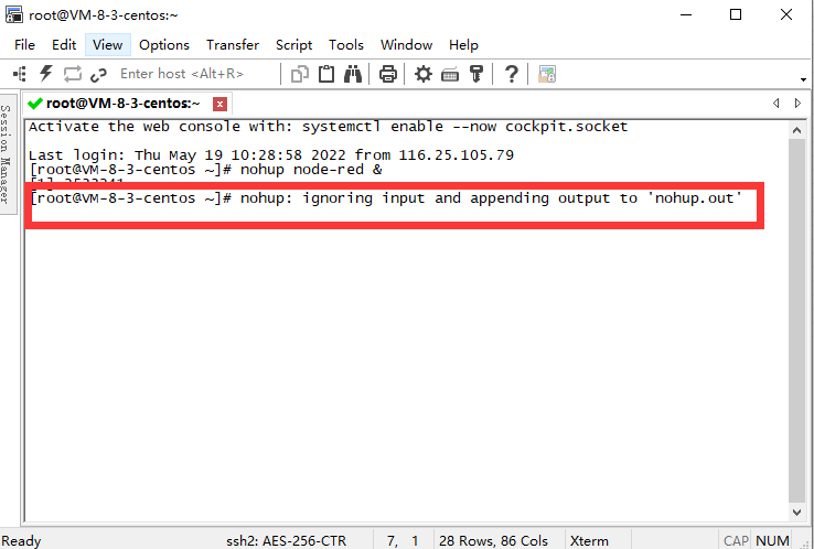
After seeing the above information, press enter.
Type in the command line exit.
The above is the installation and startup process of nodered. If you don't understand anything, you can go to the nodered official website. There are installation instructions for various systems. The address has a link at the top.
1.2 Install in Dragino Gataway
The below models from Dragino already have Node-Red installed by default. Users no need to install it by themselves.
Other gateway model doesn't support built-in Node-Red server.
2. General Use of Node-RED
This section describes some basic features of Node-RED. For more info please check the Node-RED official document.
2.1 Login to Node-RED interface
Enter your public IP address followed by the port number 1880
example:http://xxx.xx.xx.xx:1880/
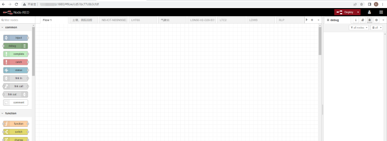
2.2 Add flow
Take NBSN95 mod1 UDP protocol as an example
After logging into the interface click "+" to create a flow

Rename the stream

Drag UDP into the editing area

The same method as above, drag and drop functions and debug into the editing area

configure UDP in

Write to the UDP port that the device node sends to the server
Example My UDP device node sends to server port 8585
just write 8585
Note: that the port that is already in use cannot be used. If the receiving fails, you need to check whether the port of the server is occupied. The sending port of the device node should not use the default port used by the server, such as a common port such as 8080.
In order to avoid data confusion, different types of nodes do not use the same UDP port, because different nodes have different data formats and different functions.

When the node successfully sends data, the effect shown in the following figure will appear

2.2.1 About function
If you are familiar with JS code, you can write it yourself
If you are not familiar, we have the JS code for each type of node, you just need to copy and paste it into it.(dragino-end-node-red-Flow)

2.3 Plot Chart for sensors
If you need data visualization, please refer to the following

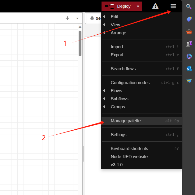
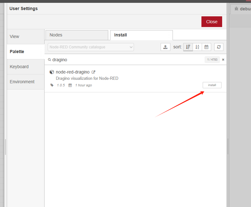
1. Click Install
2. Search the dashboard
3. Click Install

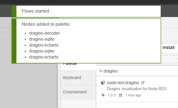
After the installation is successful, nodered will show the following node icon

2.3.1 the line chart as an example
Drag the line chart to the editing area
Just drag and drop as many as you need, or you can copy
The demo uses 3 kinds. Voltage, temperature, humidity

double click function

Adjusted to 3, because we need to display 3 charts

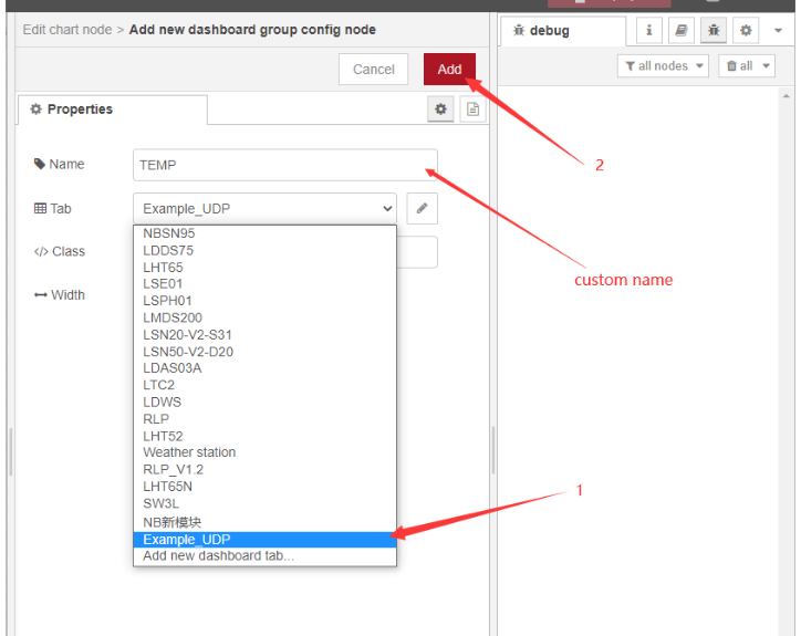
2.3.2 the chart settings
Double-click while setting up the node as above


After the display interface is defined for the first time, subsequent charts can directly select the display interface

Connect graph nodes to functions with lines
Click to deploy

Enter the server public IP + port 1880/ui
example:http://xxx.xx.xx.xx:1880/ui

At this point, the basic demonstration of nodered is completed. If you need to beautify the chart and various visualizations, you can go to the official documentation of nodered for further understanding.
2.4 Store Value
Regarding storage, we recommend two ways.
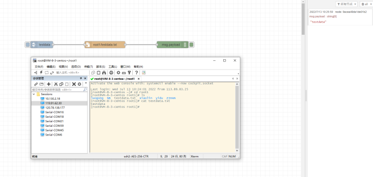
2.4.1 Method 1: Generate txt document directly
Sample JSON file: https://www.dropbox.com/sh/mduw85jcuwsua22/AAAvwPhg9z6dLjJhmZjqBf_ma?dl=0
2.4.2 Method 2: Use sqlite database
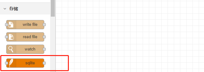
1. Install SQLite
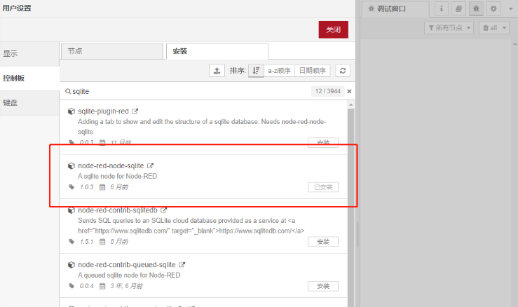
2. After the installation is successful, the nodes in the picture will appear
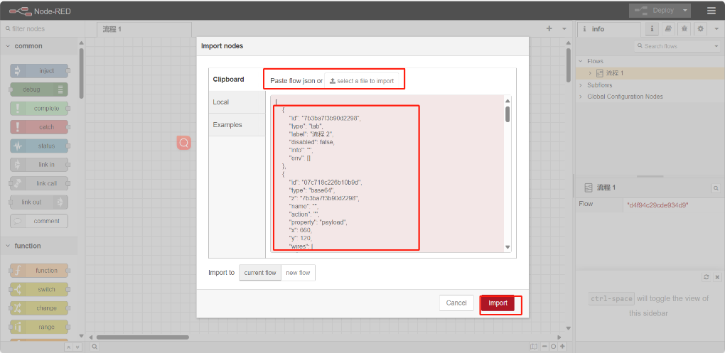
3. Import sample flow
Refer to the import example below to import the sqlite example flow
Download sample JSON file link: https://www.dropbox.com/sh/mduw85jcuwsua22/AAAvwPhg9z6dLjJhmZjqBf_ma?dl=0
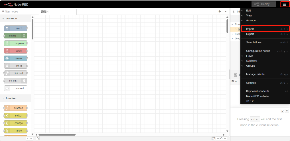
3. Import Input Flow for Dragino Sensors
Dragino provides input flow examples for the sensors.
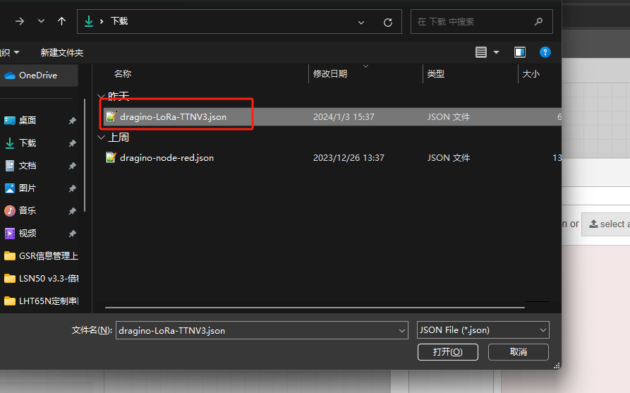
User can download the required JSON file through Dragino Node-RED input flow template.
Take LHT65N as an example (Assume this node is already registered with TTN, MQTT protocol to connect)


After the import is successful, change the MQTT in node to your TTN information


Configure information consistent with your TTN


API keys generated by the password for you

Topic modify it to the following format
v3/Application ID@ttn/devices/End device ID/up

After the modification is completed, click Deploy
4. Add Dragino node
Please do not modify the code anywhere to avoid any exceptions
The prerequisite is to install the Dragino node and the sqlite node dashboard node
The echarts library is placed in the static file of node red
Reference link: https://nodered.org/docs/user-guide/runtime/configuration
Please download the general flow and echarts files from this link:https://www.dropbox.com/scl/fo/677l8f3u3evpojcdcj3j7/h?rlkey=0iqbwf27dbyi75egmrp0p0yjx&dl=0
4.1 Installing Dragino nodes
4.2 Import General Flow

Please refer to the previous chapters for MQTT settings and sqlite installation settings
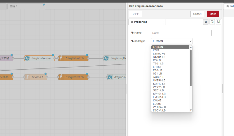
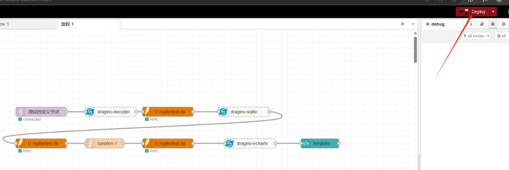
4.3 Using flow
Just double-click on the drag ino decoder node and select it from the dropdown menu
Corresponding nodes are sufficient
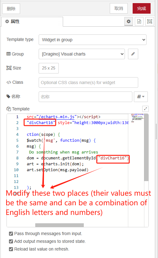
Setting the template node
When multiple nodes are needed in the same process
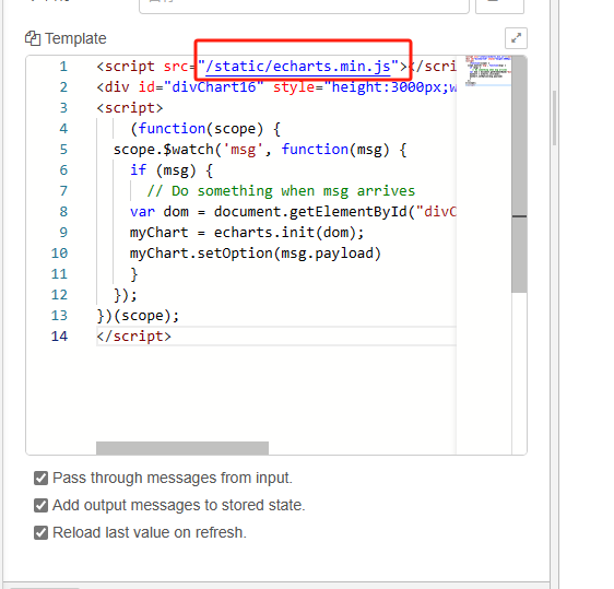
If using the NodeRed that comes with the Dragino gateway
Change to the following path
"/static/echarts.min.js"
After setting up, select deployment
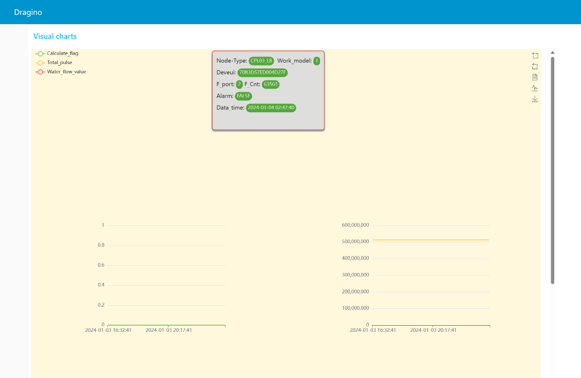
Enter the server public IP + port 1880/ui
example:http://xxx.xx.xx.xx:1880/ui
You can see the UI display effect in the following picture
5. FAQ
5.1 How to use Node-Red to schedule downlink to ChirpStack LoRaWAN Server?
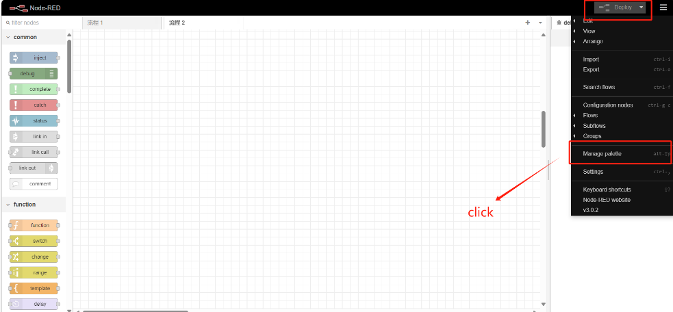
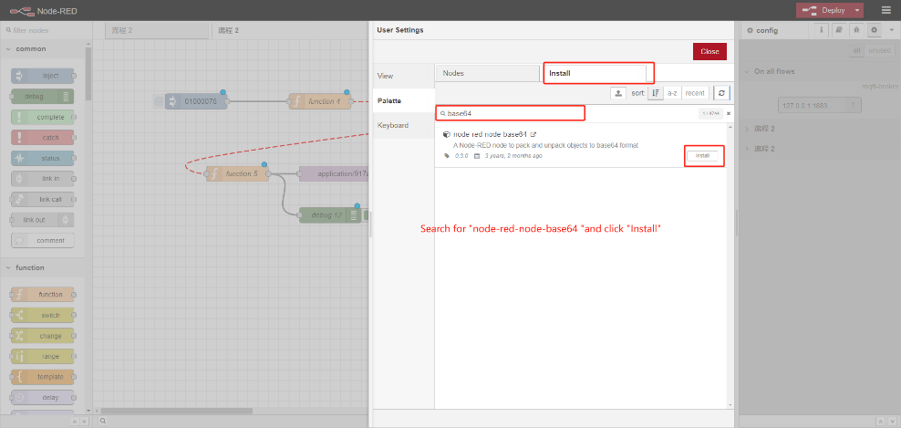
5.1.1 Install node-red-node-base64
5.1.2 Import Example Flow
The Json file for the example flow can be downloaded at this link:https://github.com/dragino/dragino-end-node-decoder/blob/main/Node-RED/chirpstack-MQTT-down.json.
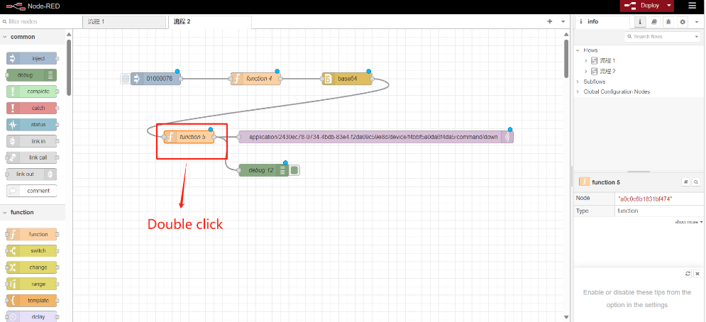
5.1.3 Establish connection
Setting up the server:
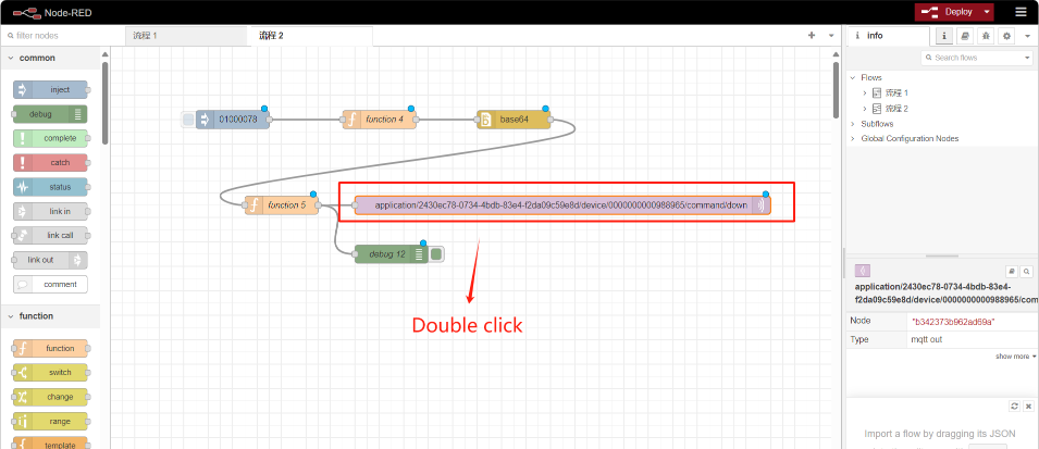
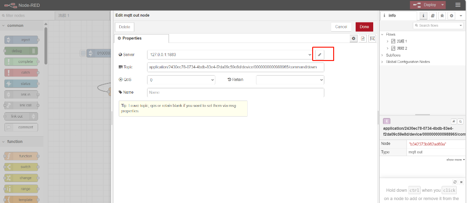
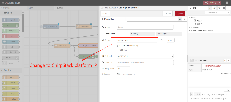
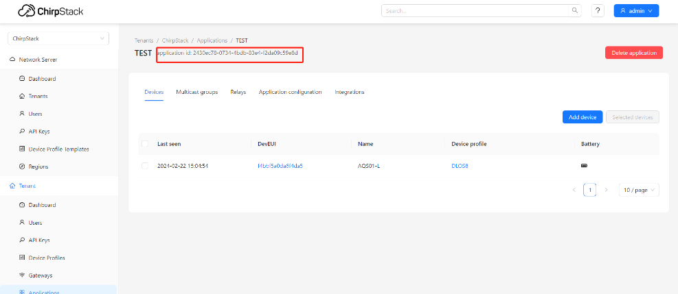
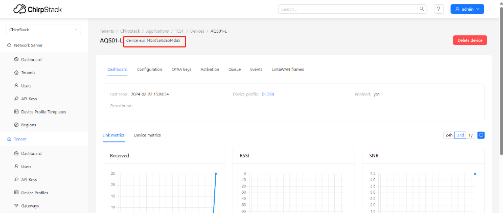
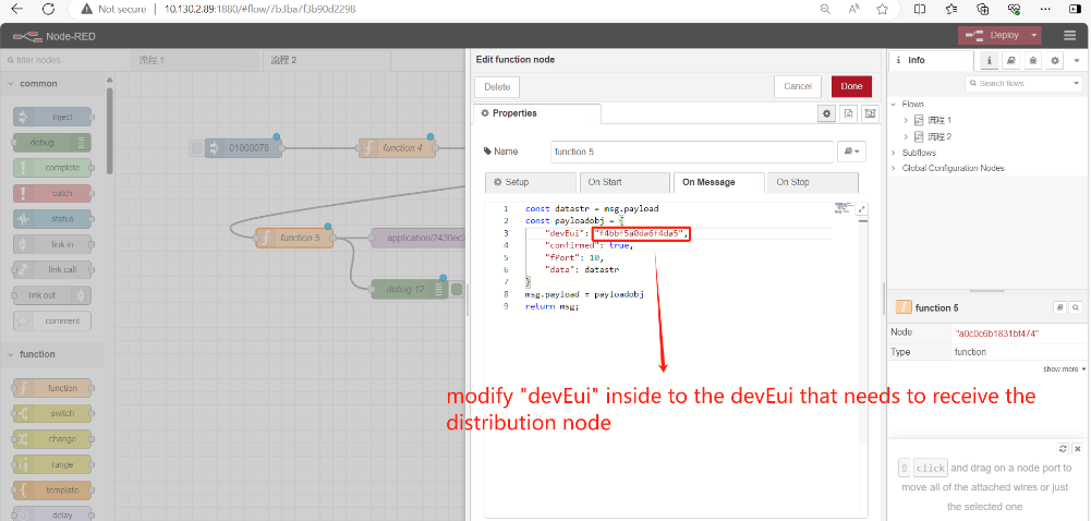
Change the theme to Application lD and DevEUl for ChirpStack:
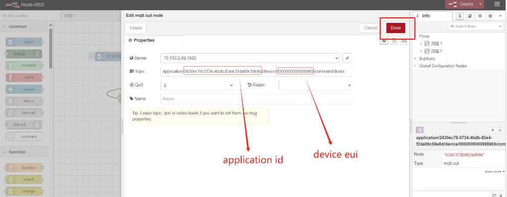
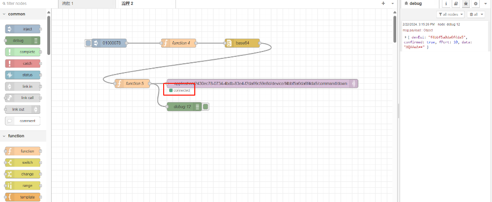
And then,
Connection established successfully:
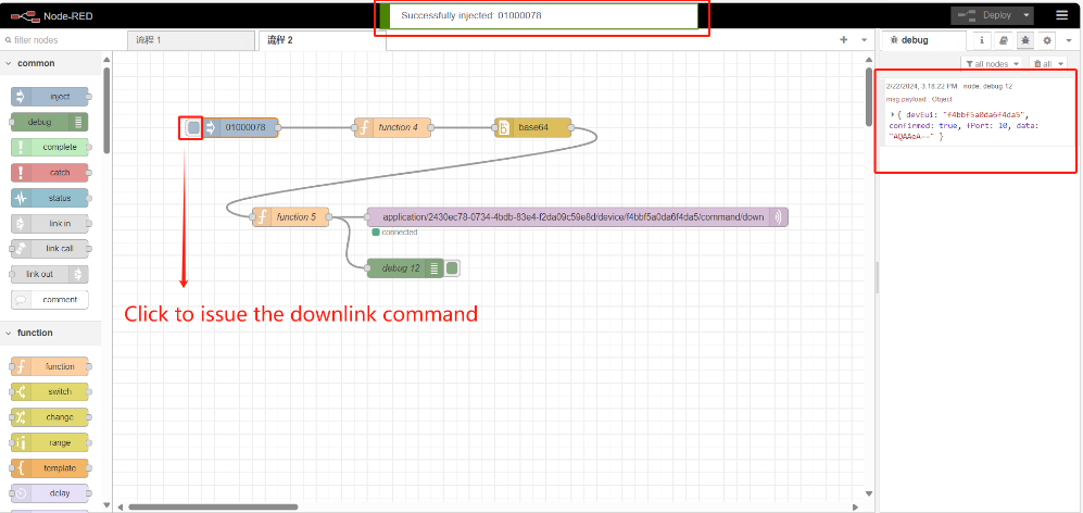
5.1.4 Input downlink command
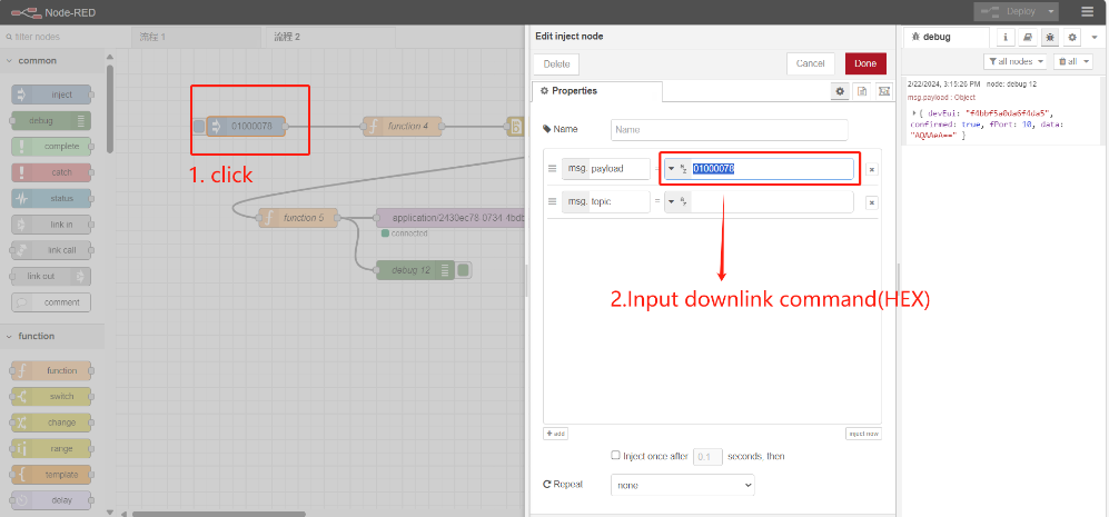
Example action video:https://youtu.be/Lqm-k5nQ5eU
5.2 How to use Node-Red to schedule downlink to TTN-V3 LoRaWAN Server?
5.2.1 Reference 5.1.1 Installing base64 nodes
5.2.2 Import Example Flow
Reference 5.1.2
Taking LT-222222-L as an example
The Json file for the example flow can be downloaded at this link:https://github.com/dragino/dragino-end-node-decoder/blob/main/Node-RED/TTN-V3-MQTT-down.json
Please refer to this video for specific operation steps: https://youtu.be/kms679e4m_Y