Communicate with ABP End Node without LoRaWAN Network Server --- LG308
Table of Contents:
- 1. Introduction
- 2. How it works
- 3. Example 1: Communicate with LT-22222-L
- 4. Example 2: Communicate to TCP Server
1. Introduction
The Dragino LoRaWAN gateway can commuicate with LoRaWAN ABP End Node without the need of LoRaWAN server. It can be used in some cases such as:
- No internet connection.
- User wants to get data forward in gateway and forward to their server base on MQTT/HTTP, etc. (Combine ABP communication method and MQTT forward together).
The basic of this feature is the decoding of LoRaWAN ABP End Node. Requirements:
- LoRaWAN End Node in ABP mode. Make sure your end node works in this mode. End node most are default set to OTAA mode
- Firmware version for below instruction: Since LG02_LG08--build-v5.4.1593400722-20200629-1120
2. How it works
Video Instruction: https://youtu.be/ZBjXwmp7rwM
Assume we have the LoRaWAN tracker LGT92 which works in ABP mode and US915 band. It has below keys:
and we have the LG308 works and US915 band and support ABP decryption. User can input these keys in LG308 so the LG308 can communicate with LGT92.
We need to input above keys in LG308 and enable ABP decryption.
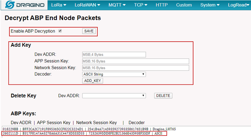
Input the ABP keys in LG308
2.1 Upstream
Now when this End Node (Dev Addr=2602111D) send a uplink packet. When this packet arrive LG308, LG308 will decode it and put the decode data on the file /var/iot/channels/2602111D . So we have this data for further process with other applications in LG308.
We can see the log of LG308 to know this packet arrive.
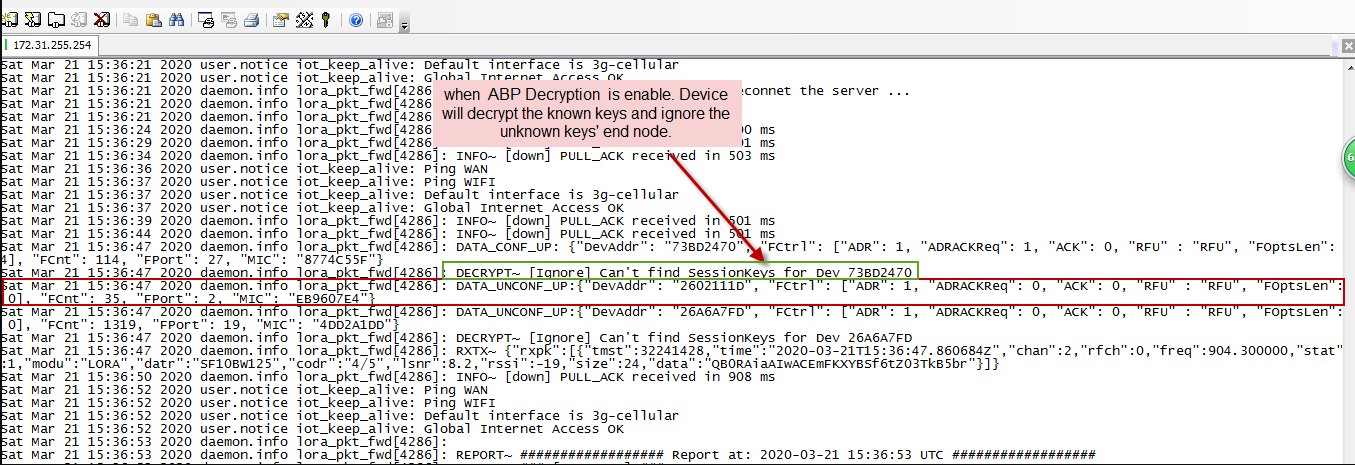
LG308 log by "logread -f" command
The data of End Node is stored in the file /var/iot/channels/2602111D. We can use hexdump command to check it.
root@dragino-1d25dc:~# hexdump /var/iot/channels/2602111D
0000000 4646 4646 4646 3946 3030 3030 3030 3546 --> Got RSSI and SNR
0000010 cc0c 0b63 0266 017f ff7f ff00 --> Payload
000001c
- RSSI: 4646 4646 4646 3946 = 0xFFFF FF9F : So RSSI = (0xFFFF FF9F - 0x100000000) = -97
- SNR: 3030 3030 3030 3546 = 0x0000 005F = 95, need to divide 10 so SNR is 9.5
- Payload: 0xcc0c 0b63 0266 017f ff7f ff00
Notice 1: The data file stored in LG308 for the end node is bin file. If the end node sends ASCII string to gateway, the output will as below:
in LGT92, use AT+SEND=12:hello world to send ASCII string
root@dragino-1d25dc:~# hexdump /var/iot/channels/2602111D
0000000 4646 4646 4646 3946 3030 3030 3030 3546
0000010 6865 6c6c 6f20 776f 726c 6400 --> Got ASCII code "hello world"
000001c
Notice 2: The upstream payload length should match the LoRaWAN length requirement (max length depends on Frequency and DR), otherwise the gateway can't decode the payload.
2.2.1 Decode Method
The decode methods: ASCII String, Decode_LHT65 doesn't affect how the sensor data is stored, they are to define how should the sensor data to be sent.
For example we have a LHT65 , works in ABP mode and gateway successful get the data, which are:
root@dragino-1baf44:~# hexdump /var/iot/channels/01826108
0000000 4646 4646 4646 4537 3030 3030 3030 3438
0000010 ccd1 7fff 7fff 017f ff7f ff00
000001c
If we choose ASCII decoder, the MQTT process will send out with mqtt-data:
Sun Sep 27 04:33:16 2020 user.notice root: [IoT.MQTT]:pub_topic[-t]: dragino-1baf44/01826108/data
Sun Sep 27 04:33:16 2020 user.notice root: [IoT.MQTT]:decoder: ASCII
Sun Sep 27 04:33:16 2020 user.notice root: [IoT.MQTT]:mqtt_data[-m]: ffffffe700000048ccd17fff7fff017fff7fff00
If we choose Decode_LHT65, the MQTT process will send out with mqtt-data
Sun Sep 27 04:36:45 2020 user.notice root: [IoT.MQTT]:pub_topic[-t]: dragino-1baf44/01826108/data
Sun Sep 27 04:36:45 2020 user.notice root: [IoT.MQTT]:decoder: Dragino_LHT65
Sun Sep 27 04:36:45 2020 user.notice root: [IoT.MQTT]:mqtt_data[-m]: {"Hum_SHT":32.7,"BatV":3.281,"TempC_DS":32.9,
"EXT":"Temperature Sensor","RSSI":-24,"TempC_SHT":85.0,"SNR":8.2,"ext_sensor":0}
Above scripts are store in /etc/lora/decoder/. User can put their scripts here and select it in the UI.
2.2.2 How to Decode My End Node
1. Configure the ABP keys for your end node in the gateway. enable ABP decode in Web UI
2. Don't choose MQTT service, use LoRaWAN.
3. When your end node send a message to the gateway, there will be a file store in /var/iot/channels. full path should be /var/iot/channels/END_NODE_DEV_ADDR
4. Use the /etc/lora/decoder/Dragino_LHT65 as template to decode your payload. This script is written in Lua language. User can manually call this script when you see the data file in /var/iot/channels by running:
/etc/lora/decoder/Dragino_LHT65 END_NODE_DEV_ADDR
5. What you see as output is the MQTT data device will upload, user's end node has different payload compare with LHT65, most properly this file will report with error. User need to modify to match the actual payload.
Some notice:
- RSSI and SNR are added when gateway receive the packet, so there is always this field.
- If you rename the file, please make it executable.
- See this link for lua.bit module: http://luaforge.net/projects/bit/
- Lua json module: http://json.luaforge.net/
- the last line return is what will be used for MQTT
- User can use other language ,not limited to Lua, just make sure the return is what you want to send.
2.2 Downstream
In LG308, we can create a file in the directory /var/iot/push for downstream purpose. We recommend using each command to generate this file. This file will be used for transmission and auto-deleted after used
The file should use below format:
dev_addr,imme/time,txt/hex,payload
Since fimware > Dragino lgw--build-v5.4.1668567157 . Support more option
dev_addr,imme/time,txt/hex,payload,txpw,txbw,SF,frequency,rxwindow,Fport
- dev_addr: Inptu the device address
- imme/time:
- imme: send downstream immediately,For Class C end node.
- time: send downstream after receive device's uplink. For Class A end node
- txt/hex:
- txt: send payload in ASCII
- hex: send payload in HEX
- payload: payload to be sent, payload lenght should match the LoRaWAN protocol requirement.
- txpw: Transmit Power. example: 20
- txbw: bandwidth:
- 1: 500 kHz
- 2: 250 kHz
- 3: 125 kHz
- 4: 62.5 kHz
- SF: Spreading Factor : SF7/SF8/SF9/SF10/SF11/SF12
- Frequency: Transmit Frequency: example: 923300000
- rxwindow: transmit on Rx1Window or Rx2Window.
- Fport: Transmit port,example:8
Completely exmaple:
- Old version: echo 018193F4,imme,hex,0101 > /var/iot/push/test
- New version: echo 018193F4,imme,hex,0101,20,1,SF12,923300000,2,8 > /var/iot/push/test
Downstream Frequency:
The LG308 will use the RX2 window info to send the downstream payload, use the default LoRaWAN settings, as below:
- EU868: 869.525Mhz, DR0(SF12BW125)
- US915: 923.3Mhz, SF12 BW500
- CN470: 505.3Mhz, SF12 BW125
- AU915: 923.3Mhz, SF12 BW500
- AS923: 923.2Mhz, SF10 BW125
- KR920: 921.9Mhz, SF12 BW125
- IN865: 866.55Mhz, SF10 BW125
- RU864: 869.1Mhz, SF12 BW125
Examples:
we can use echo command to create files in LG308 for downstream.
root@dragino-1d25dc:~# echo 2602111D,time,hex,12345678 > /var/iot/push/test
1) From logread -f of gateway, we can see it has been added as pedning.
lora_pkt_fwd[4286]: INFO~ [DNLK]Looking file : test
lora_pkt_fwd[4286]: INFO~ [DNLK]devaddr:2602111D, txmode:time, pdfm:hex, size:4, payload1:4Vx,payload_hex:77C1BB90
lora_pkt_fwd[4286]: INFO~ [DNLK] DNLINK PENDING!(1 elems).
2) When there is an upstrea from end node, this downstream will be sent and shows:
lora_pkt_fwd[4286]: INFO: tx_start_delay=1497 (1497.000000) - (1497, bw_delay=0.000000, notch_delay=0.000000)
lora_pkt_fwd[4286]: [LGWSEND]lgw_send done: count_us=3537314420, freq=923300000, size=17
3) and the end node will got:
[5764825]***** UpLinkCounter= 98 *****
[5764827]TX on freq 905300000 Hz at DR 0
Update Interval: 60000 ms
[5765202]txDone
[5766193]RX on freq 927500000 Hz at DR 10
[5766225]rxTimeOut
[5767205]RX on freq 923300000 Hz at DR 8
[5767501]rxDone
Rssi= -41
Receive data
2:12345678 --> Hex
4) If we use the command "echo 2602111D,time,txt,12345678 > /var/iot/push/test" for downstream, the end node will got:
[5955877]***** UpLinkCounter= 102 *****
[5955879]TX on freq 904100000 Hz at DR 0
Update Interval: 60000 ms
[5956254]txDone
[5957246]RX on freq 923900000 Hz at DR 10
[5957278]rxTimeOut
[5958257]RX on freq 923300000 Hz at DR 8
[5958595]rxDone
Rssi= -37
Receive data
2:3132333435363738 --> ASCII string "12345678"
3. Example 1: Communicate with LT-22222-L
Script can be download from: Example Script 1
#!/bin/sh
# This scripts shows how to use LPS8/LG308/DLOS8 to communicate with two LoRaWAN End Nodes, without the use of internet or LoRaWAN server
#
# Hardware Prepare:
# 1. LT-22222-L x 2, both are configured to work in
# a) Class C ;
# b) ABP Mode ;
# c) AT+Mod=1
# 2. LPS8,
# a) Firmware version >
# b) Input the LT-22222-L keys in LPS so LPS8 can talk with them.
# c) Lorawan server choose built-in
# d) in Custom page, select custom script to point to this script. (put this script in /etc/iot/scripts directory)
#
# How it works?
# a) Devices 1 sends a uplink payload to LPS8. LPS8 will get the DI1 and DI2 info from the payload
# b) LPS8 will send a message to Device 2 to set the Device2 DO1 = Device1 DI1, and Device DO2 = Device DI2.
# c) Device2 will change DO1 and DO2 to according to the message from LPS8, and send back a message to LPS8 with the its DO1
# and DO2 value. LPS8 will ask Device1 to change its DO1 to same as Device 2, and change the DO2 to the same as Device 2.
# ( The purpose of this step is to show that the Device2 has already do the change there).
#
# For example: If current status of Device1 and Device2 leds shows:
# Device1: DI1: ON, DI2: ON , DO1: OFF, DO2: OFF
# Device2: DI1: OFF, DI2: OFF , DO1: OFF, DO2: OFF
#
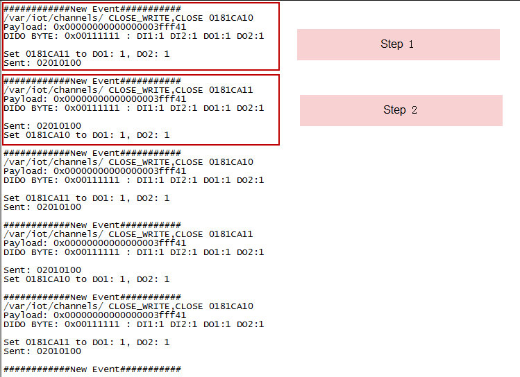
# Step2 will cause below change:
# Device1: DI1: ON, DI2: ON , DO1: OFF, DO2: OFF
# Device2: DI1: OFF, DI2: OFF , DO1: ON, DO2: ON
#
# Step3 will cause below change:
# Device1: DI1: ON, DI2: ON , DO1: ON, DO2: ON
# Device2: DI1: OFF, DI2: OFF , DO1: ON, DO2: ON
# So if a person is in the Device 1 location, he can check if the DO LED match DI LEDs on Device 1 to confirm
# whether the Device 2 has been changed.
1. Input keys
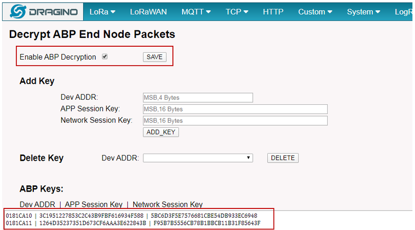
Input Keys in LPS8
2. Make sure the LPS8 and LT use the same frequency bands, choose EU868 in this test.
3. Choose Built-in server
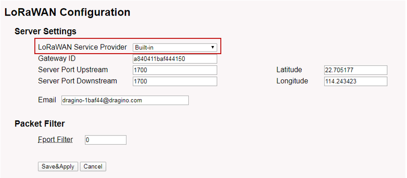
Choose Built-in server
4. Run the script.
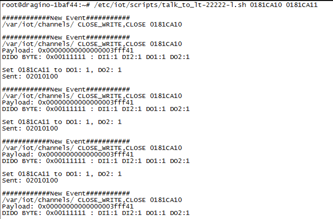
Run the script
5. Output:
Output from LPS8
4. Example 2: Communicate to TCP Server
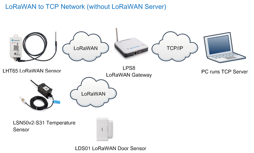
Network Structure
Full instruction video inlcude how to write scripts to fit server needed is here:
Video Instruction: https://youtu.be/-nevW6U2TsE
Note: Firmware version must be higher than lgw-5.4.1607519907
Assume we already set up ABP keys in the gateway:
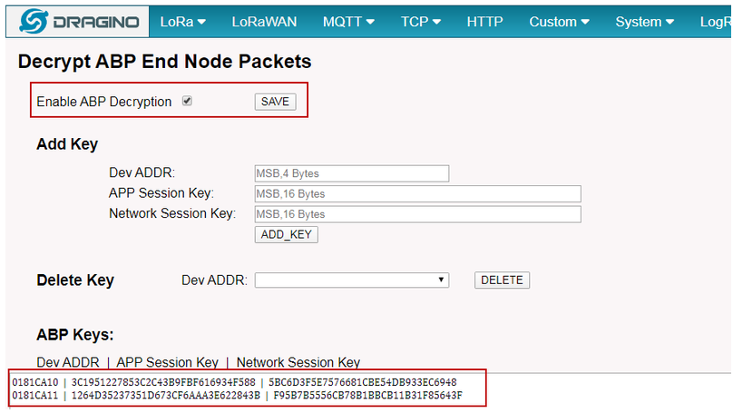
Input Keys in LPS8
run socket tool in PC
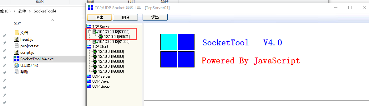
Socket tool
Input Server address and port
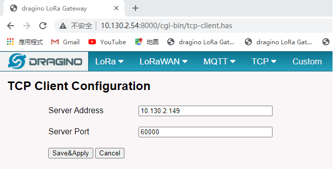
Input Server address and port
See value receive in socket tool:
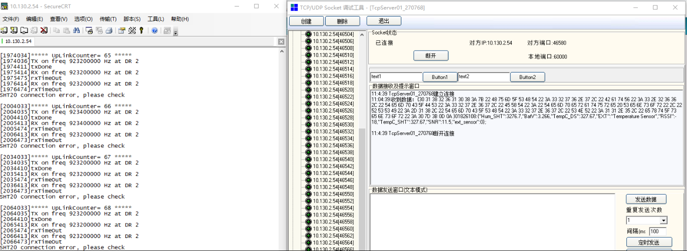
value receive in socket tool
If user want to modify the TCP connection method. He can refer: https://github.com/dragino/dragino-packages/blob/lg02/haserl-ui/root/usr/bin/tcp_process.sh. Same script is on /usr/bin of gateway.