Application Note : Communicate with Different Sensors ----- RS485-LN / RS485-BL
Table of Contents:
- 1. Introduction
- 1.1 Example 1: Connect to Leak relay and VFD
- 1.2 Example 2: Connect to Pulse Counter
- 1.3 Example 3: Use RS485-LN with energy meters
- 1.4 Example 4: Circuit Breaker Remote Open Close
- 1.5 Example 5: SEM Three Energy Meter with RS485-BL or RS485-LN
- 1.6 Example 6: CEM C31 485-T1-MID Energy Meter with RS485-LN
- 1.7 Example 7: Schneider Electric PLC M221 with RS485-BL
- 1.8 Example 8: This sketch is supposed to test Dragino RS485-BL (Modbus master), using an Arduino UNO as a Modbus slave.
1. Introduction
This article provide the examples for RS485-LN to connect to different type of RS485 sensors.
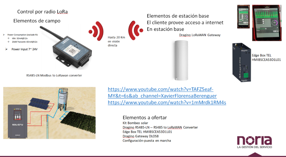
1.1 Example 1: Connect to Leak relay and VFD
This instruction is provided by Xavier Florensa Berenguer from NORIA GRUPO DE COMPRAS. It is to show how to use RS485-LN to connect to Relay and VFD and communicate with Mobile. The structure is like below:
Connection
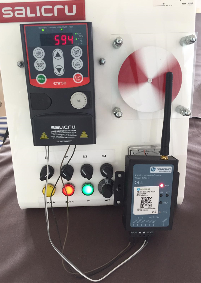
Connection
Related documents:
- System Structure: Solar Pump with Dragino
- Explanation on how to integrate to Node-red and to the Mobile Phone, and with link to the Github code: Configure Manual
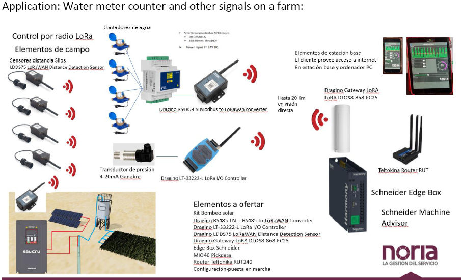
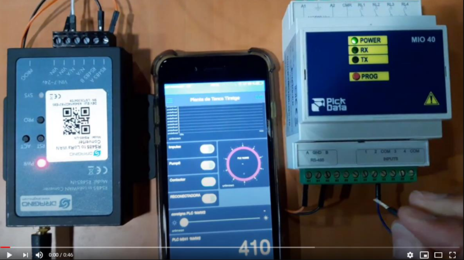
1.2 Example 2: Connect to Pulse Counter
This instruction is provided by Xavier Florensa Berenguer from NORIA GRUPO DE COMPRAS. It is to show how to use RS485-LN to connect to Pulse Counter and communicate with Mobile. This example and example 2 compose the structure for a farm IoT solution. The structure is like below:
Connection
Connection
Related documents:
- Configure Document: Pickdata MIO40 water pulse counter to LoRa with Dragino RS485-LN
1.3 Example 3: Use RS485-LN with energy meters
1.3.1 OverView
Note:The specifications of each energy meter are different, please refer to your own energy meter specifications.
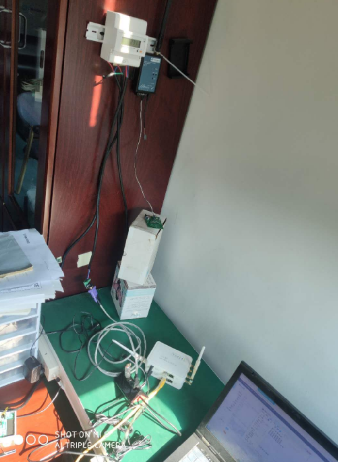
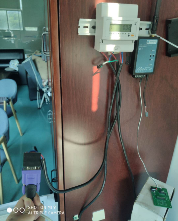
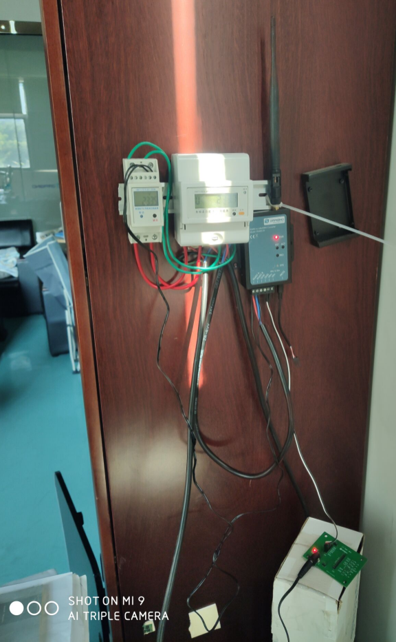
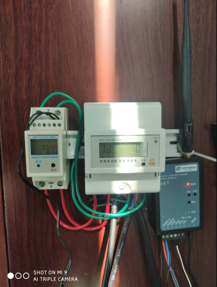
This example describes a single-phase meter.This is the connection between the RS485-LN and the energy meter.
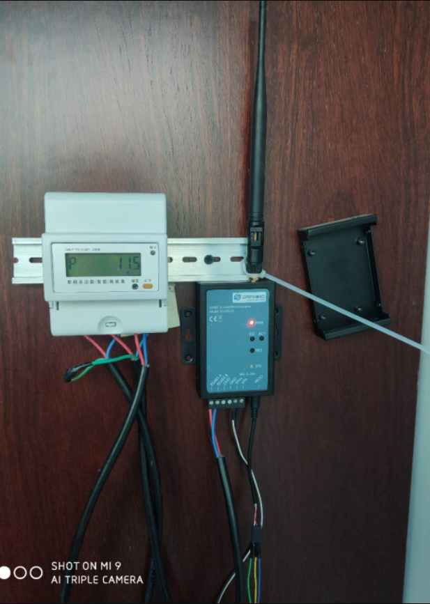
Connection1
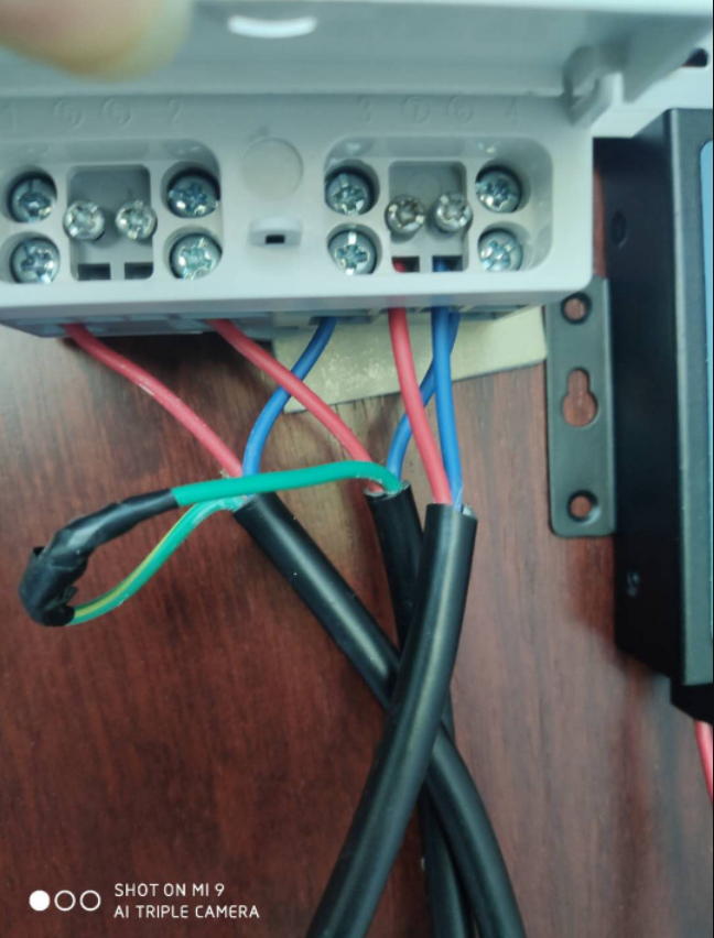
How to connect with Energy Meter:
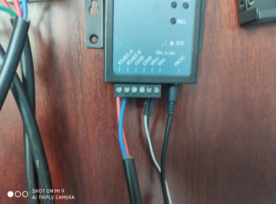
Follow the instructions of the electric energy meter to connect the phase line and the neutral line, and then connect 485A+ and 485B- to RS485A and RA485B of RS485-LN respectively.
The RS485-LN can be powered by 7 ~ 24V DC power source. Connection as below
Power Source VIN to RS485-LN VIN+
Power Source GND to RS485-LN VIN-
Once there is power, the RS485-LN will be on.
Connection2
Connection3
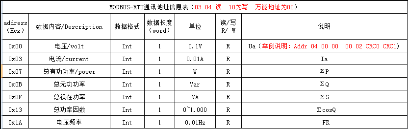
1.3.2 How to use the parameters of the energy meter and MODBUS commands
If the user needs to read the parameters of the electric energy meter and use the modbus command,please refer to the appendix of the MODBUS communication protocol in the user manual of the energy meter.
Example: AT+COMMAND1=01 03 00 00 00 01 84 0A
- The first byte : slave address code (=001~247)
- The second byte : read register value function code
- 3rd and 4th bytes: start address of register to be read
- 5th and 6th bytes: Number of registers to read
- 7th and 8th bytes: CRC16 checksum from bytes 1 to 6.
How to parse the reading of the return command of the parameter:
Example: RETURN1:01 03 02 08 FD 7E 05
- The first byte ARD: slave address code (=001~254)
- The second byte: Return to read function code
- 3rd byte: total number of bytes
- 4th~5th bytes: register data
- The 6th and 7th bytes: CRC16 checksum
- 08 FD is register data. Use short integer 16 bits to convert to decimal, get 2301, then 230.1V is the voltage.
1.3.3 How to configure RS485-LN and parse output commands
RS485-LN provides two configuration methods: AT COMMAND and DOWNLINK.
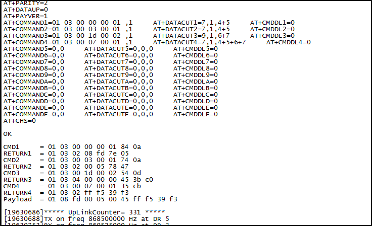
1.3.3.1 via AT COMMAND
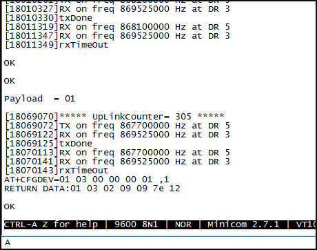
First, we can use AT+CFGDEV to get the return value, and we can also judge whether the input parameters are correct.
If the configured parameters and commands are incorrect, the return value is not obtained.
AT COMMAND
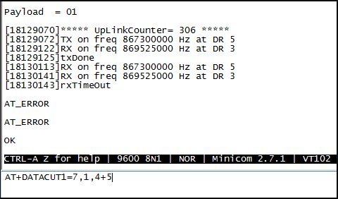
a: length for the return of AT+COMMAND
b: 1: grab valid value by byte, max 6 bytes; 2: grab valid value by bytes section, max 3 sections.
c: define the position for valid value.
AT COMMAND
PAYLOAD is available after the valid value is intercepted.
AT COMMAND
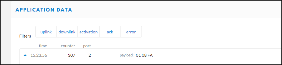
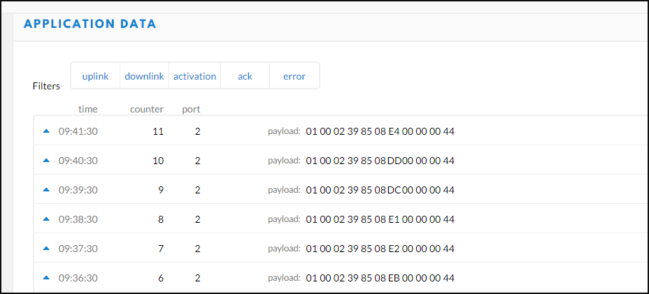
You can get configured PAYLOAD on TTN.
AT COMMAND
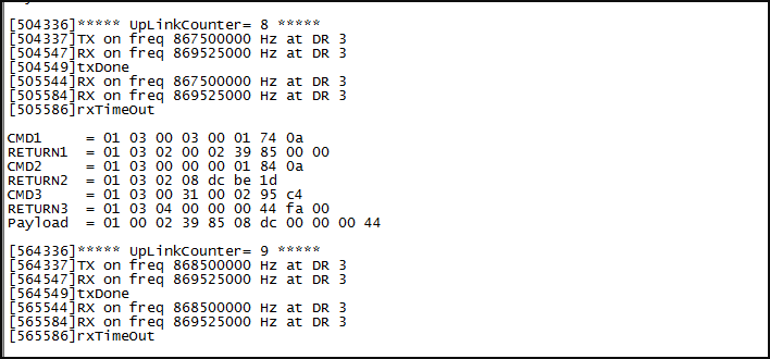
Example:
CMD1: Read current data with MODBUS command. address: 0x03 AT+COMMAND1= 01 03 00 03 00 01,1
RETURN1: 01 03 02 00 02 39 85 00 00(return data)
AT+DATACUT1: 9,1,4+5+6+7 Take the return value 00 02 39 85 as the valid value of reading current data and used to splice payload.
CMD2: Read voltage data with MODBUS command. address: 0x00 AT+COMMAND2= 01 03 00 00 00 01,1
RETURN2: 01 03 02 08 DC BE 1D(return data)
AT+DATACUT2: 7,1,4+5 Take the return value 08 DC as the valid value of reading voltage data and used to splice payload.
CMD3: Read total active energy data with MODBUS command. address: 0x0031 AT+COMMAND3= 01 03 00 31 00 02,1
RETURN3: 01 03 04 00 00 00 44 FA 00(return data)
AT+DATACUT3: 9,1,4+5+6+7 Take the return value 00 00 00 44 as the valid value of reading total active energy data and used to splice payload.
Payload: 01 00 02 39 85 08 DC 00 00 00 44
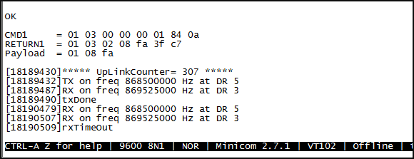
AT COMMAND
01 is device address,00 02 is the current, 08 DC is the voltage,00 00 00 44 is the total active energy.
AT COMMAND
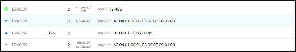
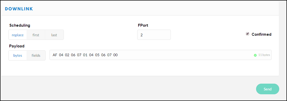
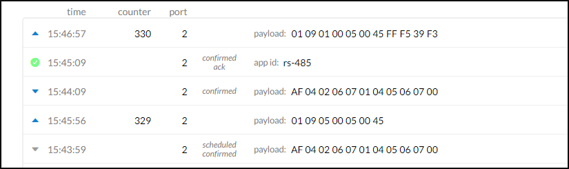
1.3.3.2 via LoRaWAN DOWNLINK
DOWNLINK
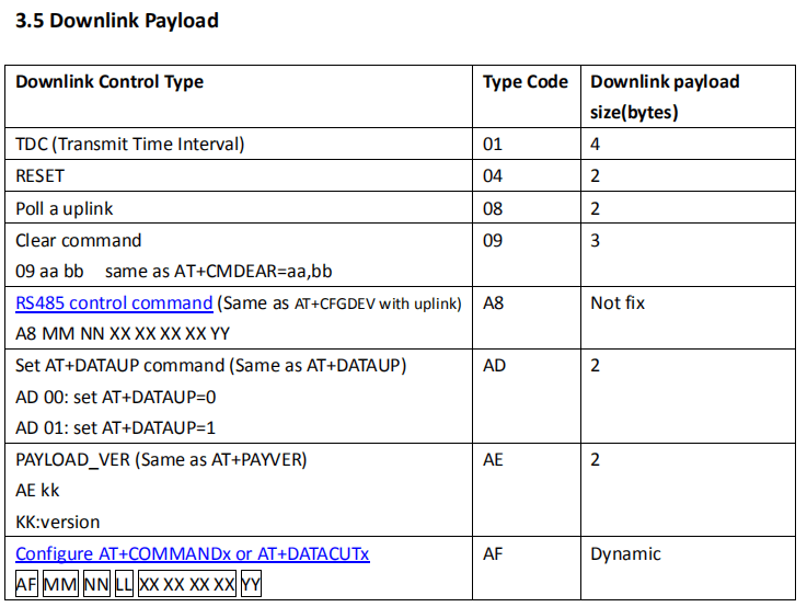
Type Code 0xAF
Note: if user use AT+COMMANDx to add a new command, he also need to send AT+DATACUTx downlink.
Format: AF MM NN LL XX XX XX XX YY
Where:
MM: the ATCOMMAND or AT+DATACUT to be set. Value from 01 ~ 0F,
NN: 0: no CRC; 1: add CRC-16/MODBUS ; 2: set the AT+DATACUT value.
LL: The length of AT+COMMAND or AT+DATACUT command
XX XX XX XX: AT+COMMAND or AT+DATACUT command
YY: If YY=0, RS485-LN will execute the downlink command without uplink; if YY=1, RS485-LN
will execute an uplink after got this command.
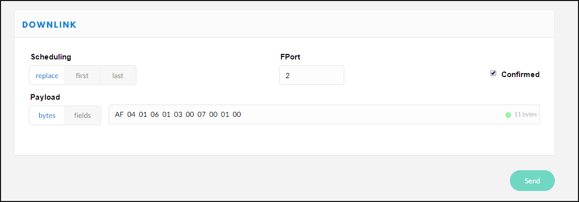
Example:
AF 03 01 06 0A 05 00 04 00 01 00: Same as AT+COMMAND3=0A 05 00 04 00 01,1
DOWNLINK
DOWNLINK
DOWNLINK
DOWNLINK
DOWNLINK
1.3.4 How to configure and output commands for RS485 to USB
This step is not necessary, it is just to show how to use a normal RS485 to USB adapter to connect to the meter to check the input and output. This can be used to test the connection and RS485 command of the meter without RS485-LN.
First, connect the A+ and A- of the USB to the 485 A and 485 B of the energy meter.
Open the serial port debugging, set the send and receive to HEX.
Baud rate: 9600
check digit: Even
USB
USB
The configuration command is consistent with the AT command, input the hexadecimal command directly into the serial port, and the serial port will output the command.
Example: input:01 03 00 31 00 02 95 c4
output:01 03 04 00 00 00 42 7A 02
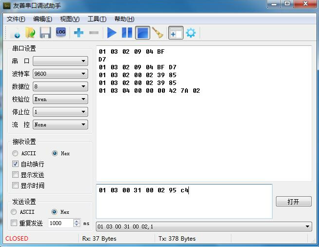
USB
1.3.5 How to configure multiple devices and modify device addresses
If users need to read the parameters of multiple energy meters, they need to modify the device address, because the default device address of each energy meter is 01.
Set the device address according to the parameters in the appendix of the MODBUS communication protocol.
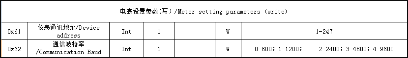
Example: These two meters are examples of setting parameters and device addresses.
First of all, since the default device address of the energy meter is 01, the configuration of two energy meters will conflict, so we first connect an energy meter and configure the device address.
We can use AT+CFGDEV to set the device address.
We modify the device address 01 of the first energy meter to 02.
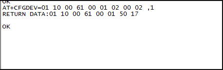
- 01: device adaress
- 10: function code
- 00 61:Register address
- 00 01:Number of Registers
- 02:Number of bytes
- 00 02:Modified device address
- 1:Check code
The device address setting of the energy meter is complete.
Another energy meter is a single active energy meter with a floating-point format.
Its default device address is 01, and the following are the parameters for configuring two energy meters.
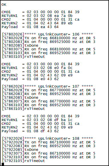
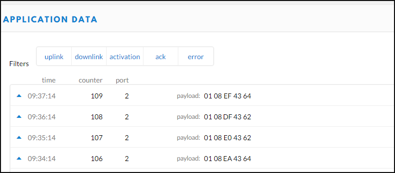
PAYLOAD: 01 08 DF 43 62
- 08 DF is the valid value of the meter with device address 02.
- 43 62 is the valid value of the meter with device address 01.
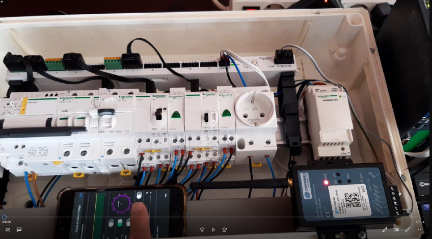
1.4 Example 4: Circuit Breaker Remote Open Close
This instruction is provided by Xavier Florensa Berenguer from NORIA GRUPO DE COMPRAS. It is to show how to use RS485-LN to connect to SCHNEIDER SMART and Monitor and control your cabinet remotely with no wires and with Dragino RS485-LN LoRaWAN technology.
The structure is like below:
Connection
- Configure Documen: Circuit Breaker Remote Open Close
1.5 Example 5: SEM Three Energy Meter with RS485-BL or RS485-LN
This instruction is provided by Xavier Florensa Berenguer from NORIA GRUPO DE COMPRAS. It is to show how to use RS485-BL to connect to SEM Three Energy Meter and send the data to mobile phone for remote minitor. The structure is like below:
- Configure Document For RS485-BL: Connect to SEM Three
- Configure Document for RS485-LN: Connect to SEM Three
1.6 Example 6: CEM C31 485-T1-MID Energy Meter with RS485-LN
This instruction is provided by Xavier Florensa Berenguer from NORIA GRUPO DE COMPRAS. It is to show how to use RS485-LN to connect to CEM C31 485-T1-MID and send the data for remote minitor. The structure is like below:
- Configure Document For RS485-LN: CEM C31 485-T1-MID
1.7 Example 7: Schneider Electric PLC M221 with RS485-BL
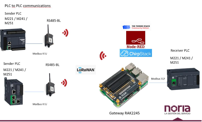
Network Structure
1.8 Example 8: This sketch is supposed to test Dragino RS485-BL (Modbus master), using an Arduino UNO as a Modbus slave.
This sketch uses 4 registers: some of them can be set by Dragino with a command, another is used to store value from a DS18B20 temperature sensor, or a random generated number. All data is 16bit uint, but the sketch shows also how to represent booleans and negative numbers.
In the next days I will be adding more documentation, but I think it already explains users how to build their own modbus sensor to pair with Dragino RS485-BL.
This is released the code under GNU LGPL licence on Github:
https://github.com/zorbaproject/ArduinoModbusForDraginoRS485