Dragino RS485 tool is designed to provide a friendly way to user to configure Dragino RS485 Wireless Sensor such as : RS485-LN, RS485-LB, RS485-BL, RS485-NB.
The RS485 tool provide below features:
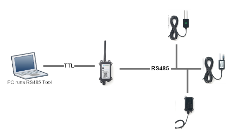
To use Dragino RS485 Configure Tool. User need to run the tool in PC and use the TTL connection to Dragino End Node, and RS485 end node should connect to the RS485 Sensors for debug or configure.
Download RS485 Configure Tool.
warning: Please do not input multiple instructions at once for a site, as this may result in incorrect data
Below is the block diagram of the RS485 Tool:
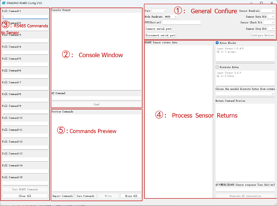
Below is the block diagram of the RS485 Tool V1.2:
After Connect End Node. The Console Window will shows all the output from RS485 End Node.
User can also Send AT Commands to RS485 End Node in this window.
This area is used to configure what RS485 Commands the End Node should send to the RS485 sensors to get the sensor value.
Example:
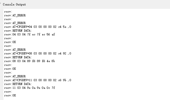
Test RS485 Commands: After configure poll commands. Click this button then the tool will generate related AT+COMMANDS and send to the End node to test and get return.
RS485 sensors will return a string, to make it more efficient to process via LoRaWAN packets, we can fetch the valid chars from the returns in the process sensor returns area.
Example:
User configure below commands :
Then Click "Test RS485 Commands". End Node will then send these three commands to RS485 sensors one by one and waiting for returns.
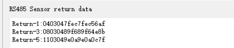
Their returnes will be shown in "RS485 Return Data" Area, such as below:
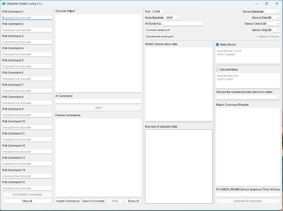
Use can choose to get "Discrete Data Bytes" or "Bytes Blocks":
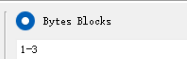 Select the 1st - 3rd bytes from the return.
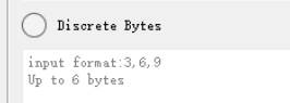 Select the 3rd, 6th, 9th bytes from the return.
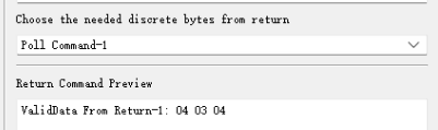 After select the byte fetch method. User can see preview the result. This photo shows to fetch the Block 1~3 from the first return.
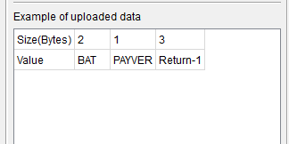 Based on the AT command in the preview window, the node will upload data in the format of the left image
Below is the full screen shot:
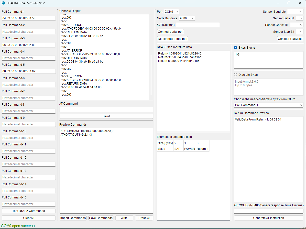
AT+CMDDL: This specify the delay for RS485 End Node to wait for the RS485 sensors return. If RS485 sensors doesn't reply in this time. End Node will consider there is no reply.
Generate AT Instructions: After All testing goes fine with Poll Command & Return Process. User can press this button to generate the AT Commands which is for the Ene Node.
This window show the commands to be flash into the RS485 end node.
link:https://youtu.be/l9fLE3ekY4I
1.No spaces are required between each byte of the inquiry frame
2.Improve the prompt box
3.AT instruction coverage function
4.Button function prompt
1.Fixed overwrite failure when AT instruction has multiple parameters
2.Add Payload Structure Window
Fixed bug in V1.2
1.When the input cut value exceeds the number of bytes returned, an incorrect AT instruction will be generated
New:
1.Control the inquiry time input box between inquiry frames
2.The inquiry frame does not require CRC verification input
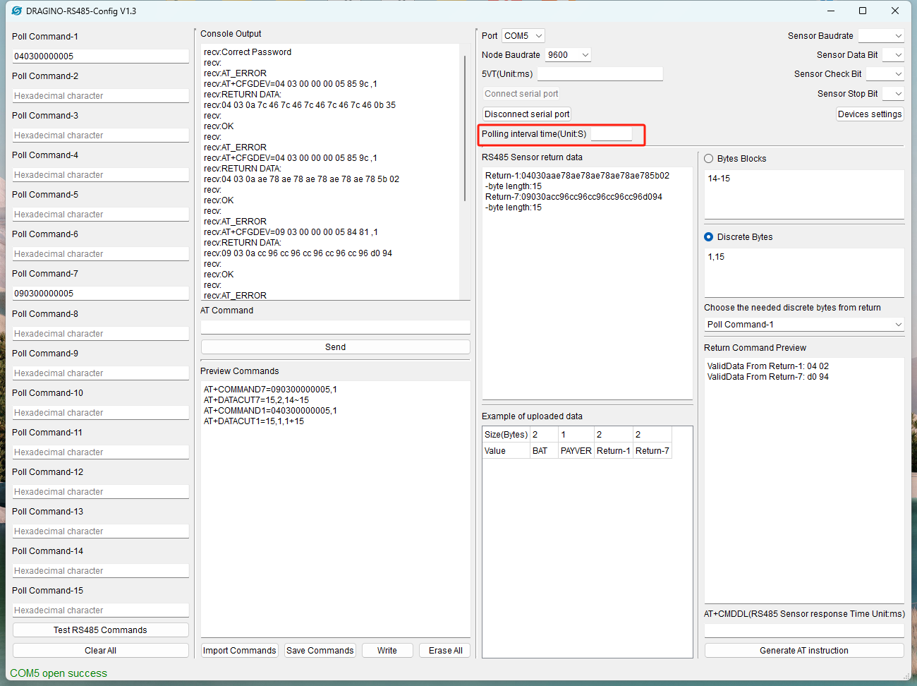
Added a password input box.
When using NB modules or nodes with access passwords other than 123456.
Enter the password before connecting to the serial port

1. Add Payload Structure Window(Done at v1.2)
2. Modify Chars to looks nicer ( Done at v1.1)